This is an old revision of the document!
Table of Contents
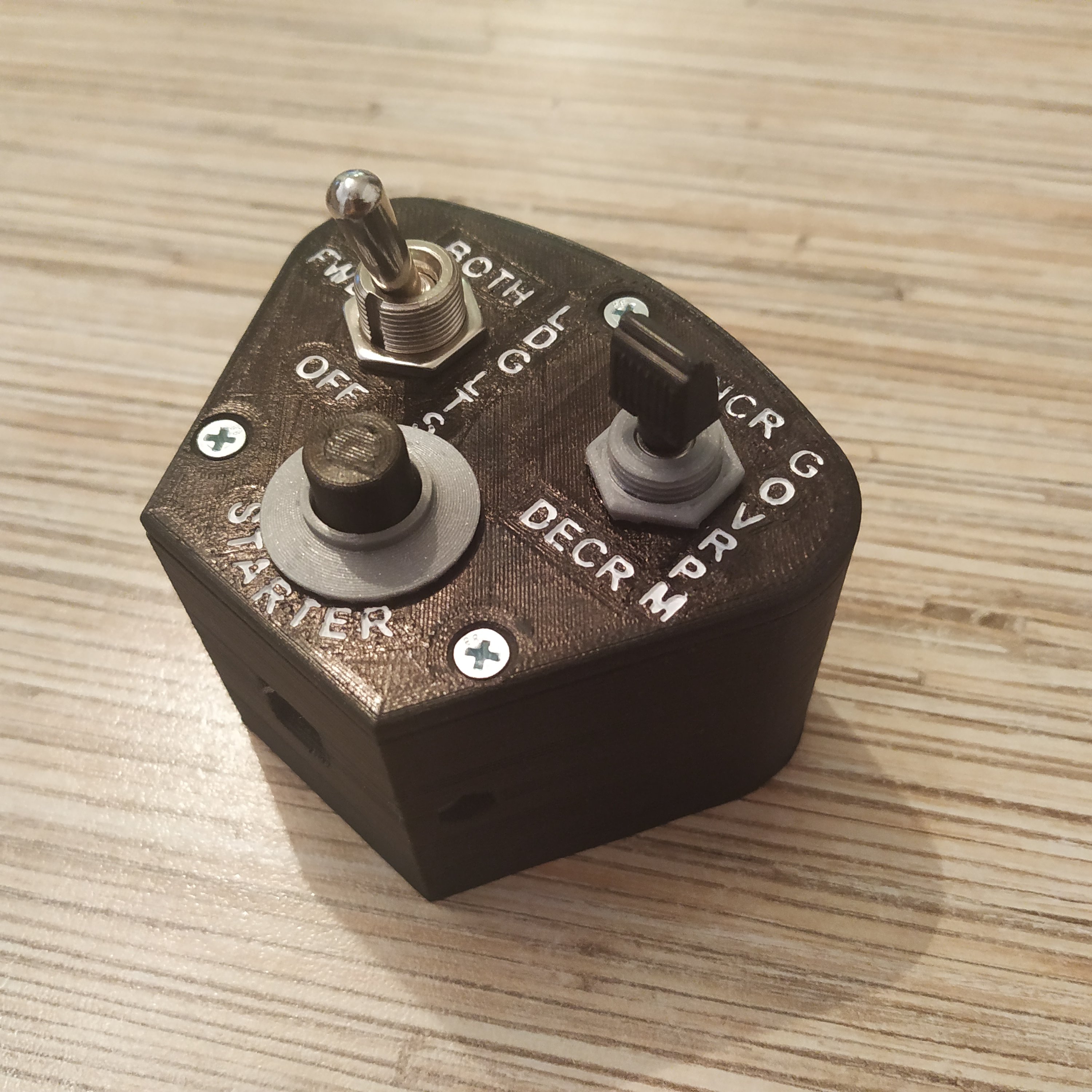
Bell 407 scale collective head
Summary
This is a semi-scale Bell 407 style head. This version is modeled after the 407GXP switch panel, as it has more buttons on it than others. From what I've seen, there are a lot of variants of this head with different buttons on it. Proportions should be accurate, with some minimal deviation needed to adapt the head to the existing simchair MKIV collective lever body with a physical latch.
Components
- 1 x KN3(B)-101AP-A1 ON-OFF switch
- 2 x KN3(B)-103A-A3 ON-OFF-ON switch
- 1 x KN3(B)-223 switch
- 1 x PBS-10B2 button
- 1 x PBS-16B button
- 1 x SAC-01 switch cover
- 1 x 12x12x5mm tact button (or similar height)
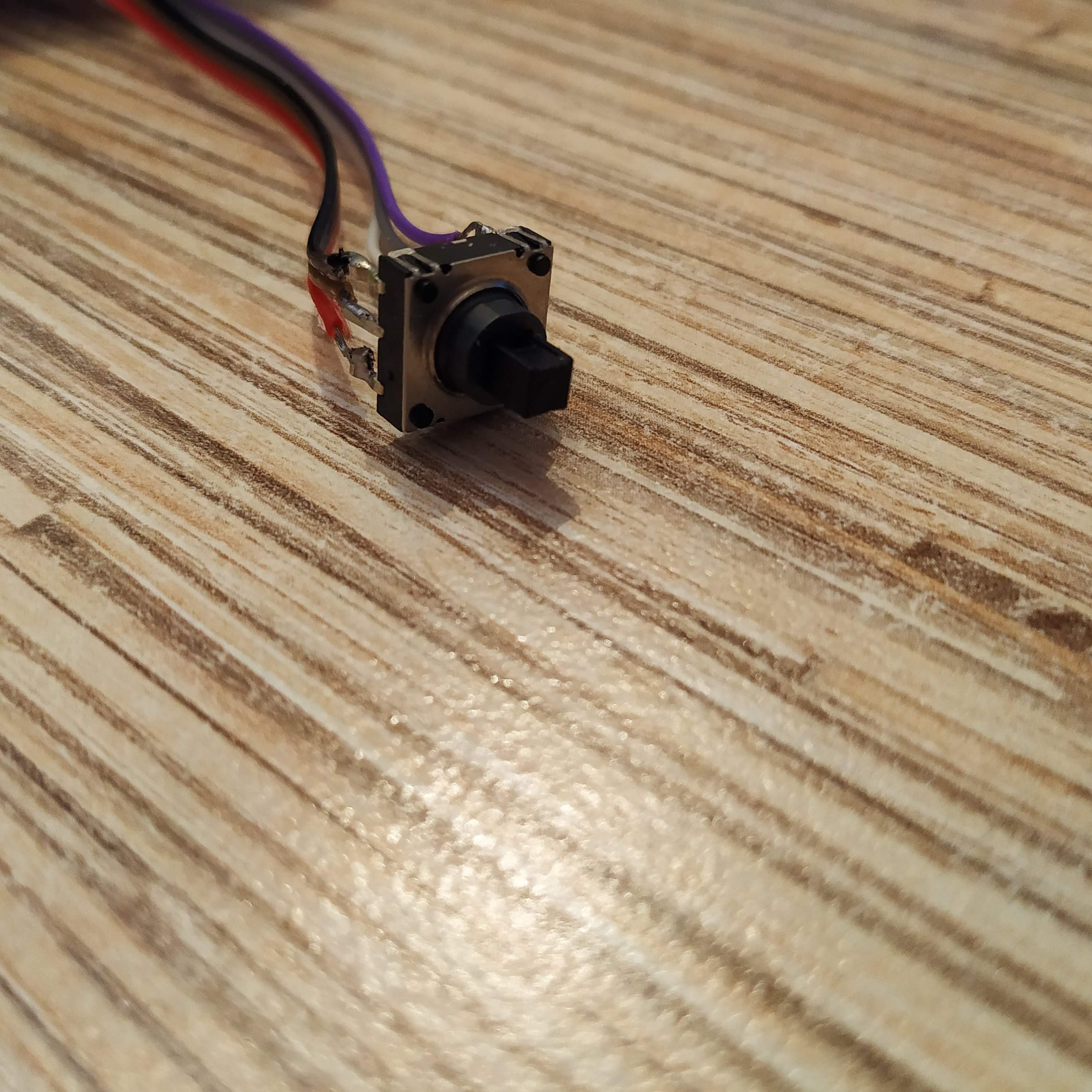
- 1 x 10mm 5-way hat switch (https://cutt.ly/BxZti0f)
- 9 x M3x50mm round screws and nuts
- 1 x M3x40mm round head screw and nut
- 1 x Arduino Pro Mini
- 1 x TJ8P8C Ethernet socket (12,5x15x17,6mm)
Repository path
simchair4_models\printable components\peripherals\helicopter\collective lever\c_switch panels\b407 collective head
Assembly manual
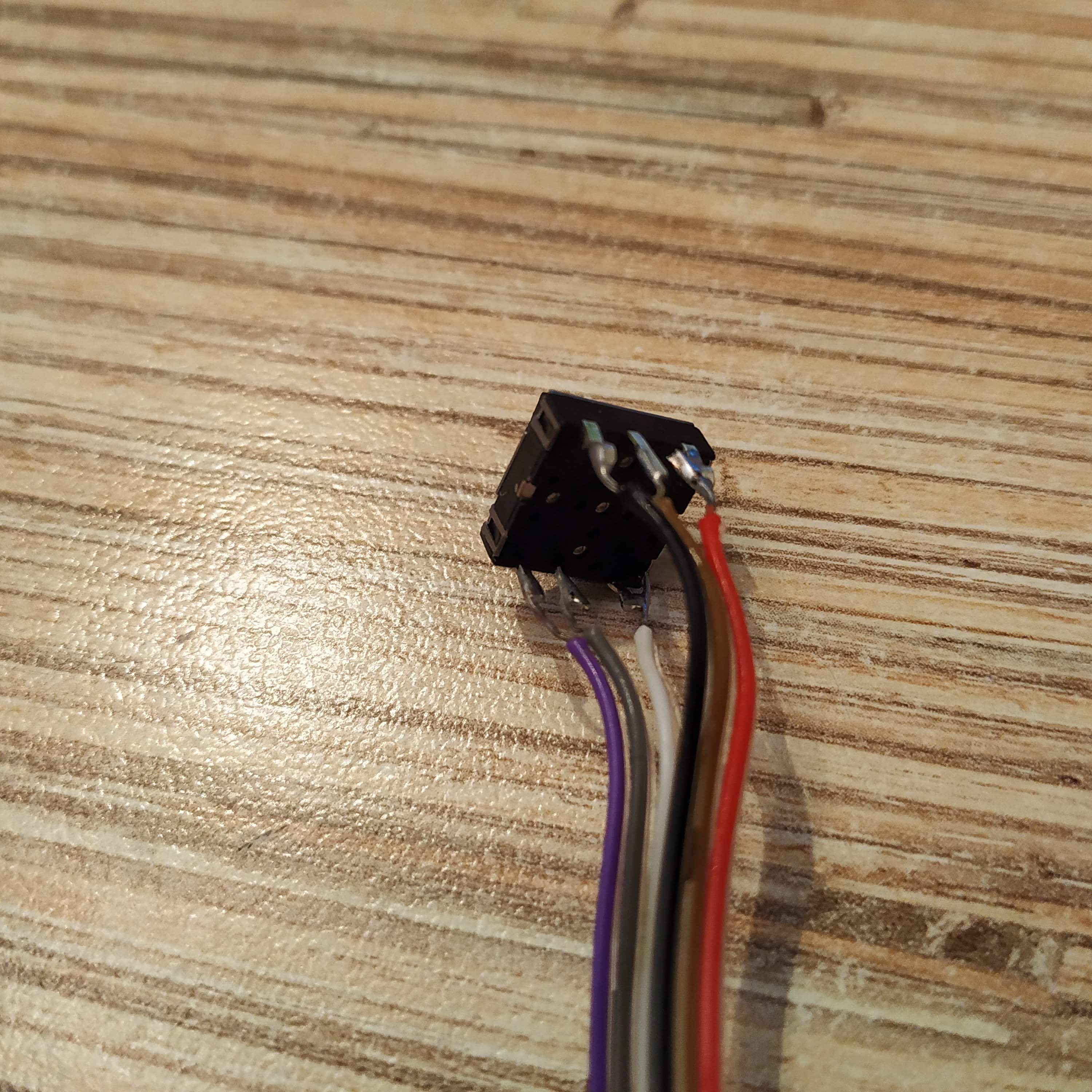
1. Solder wires to the hat switch. The ground wire is the top-left (black) wire. Note how it's slightly closer from the center pin than the other one. Check that every direction of the hat works with a multimeter, connect it between the GND pin and each of the other pins.
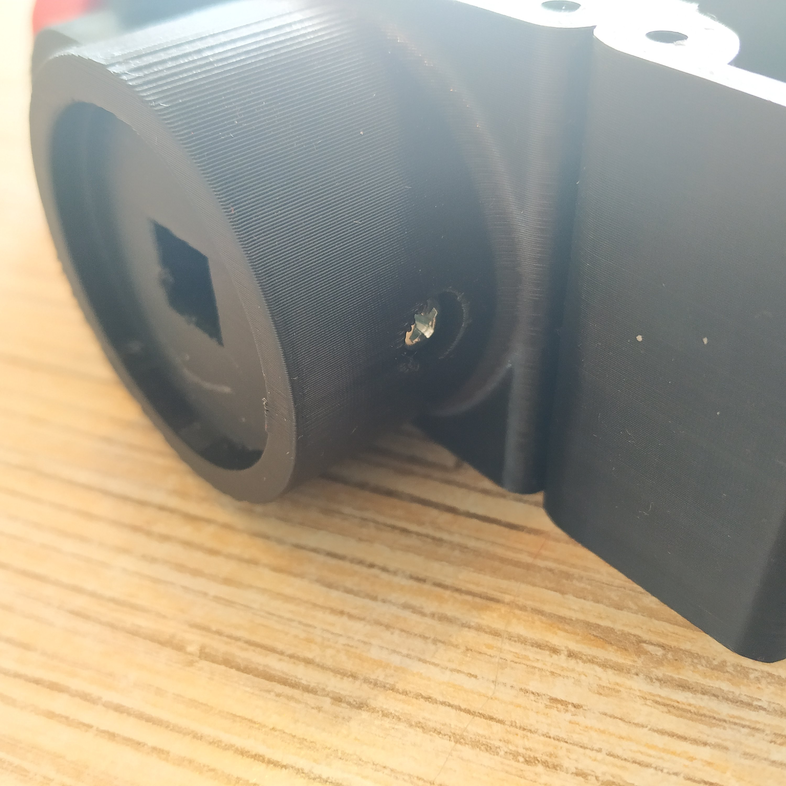
2. Put the head onto the lever and drill the hole on the side for the bolt that holds the head on the lever. Put the nut into the socket on the other side after it's done.
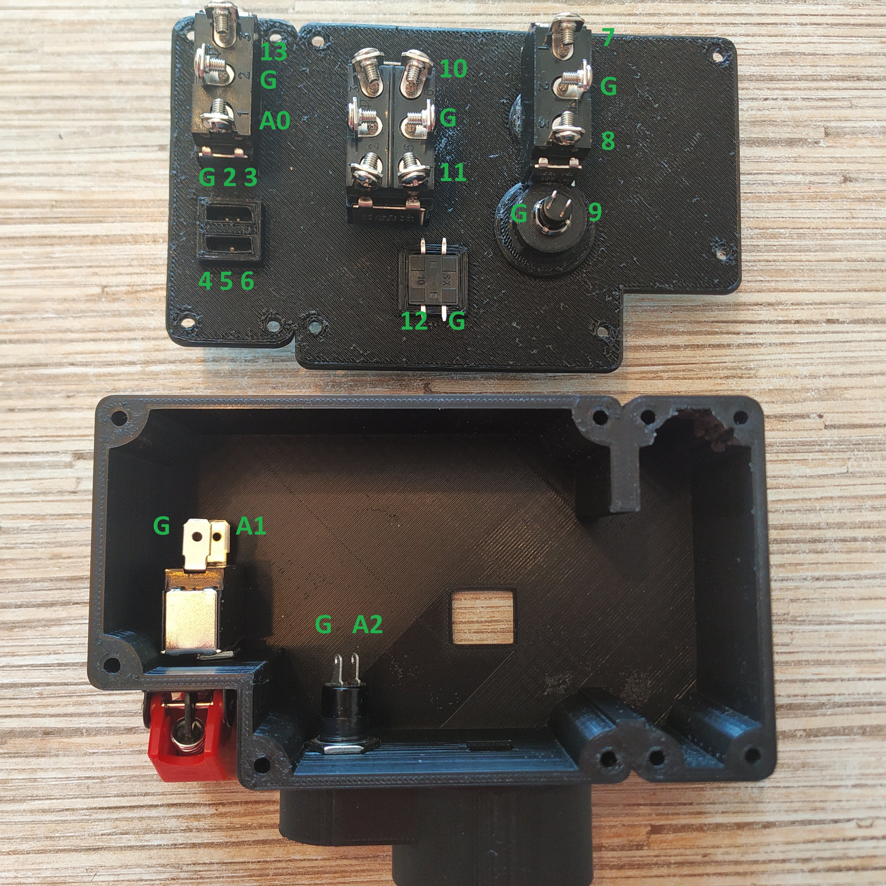
3. Insert switches to their sockets (the momentary switch goes to the starter slot, and the 2-way one goes to the wall of the panel under the red cap) and solder wires to the pins of Arduino Pro Mini as shown in the picture below:
4. Solder an ISP header to Arduino Pro Mini board. Solder a 7-wire cable to an Ethernet socket. Connect it to Pro Mini board as follows:
| CONN POINT A | CONN POINT B |
|---|---|
| ETH SOCKET PIN 1 | VCC |
| ETH SOCKET PIN 2 | GND |
| ETH SOCKET PIN 3 | SCL (A5) |
| ETH SOCKET PIN 4 | SDA (A4) |
| ETH SOCKET PIN 5 | Rx |
| ETH SOCKET PIN 6 | Tx |
| ETH SOCKET PIN 7 | DTR |
