Table of Contents
Compact collective head
Summary
This head is perfect for motion platform users, as it can be used without a counterweight, or even without the pneumatic mod (although I do highly recommend the latter!). It also works well, as a generic gaming device – The shape allows using it as a throttle lever on a single-engine airplane when mounted to the GUNDE chair onto the Malinda mount at 30 degrees.
Components
- 4 x MTS-123 or MTS-103 switches (MTS-123, (on) - off (on) momentary ones, are preferred)
- 2 x PBS-10B2 buttons
- 1 x KY-023 ministick board
- 4 x M3x25mm screws and nuts
- 1 x Arduino Pro Mini
Repository path
simchair4_models\printable components\peripherals\helicopter\collective lever\c_switch panels\compact integrated head
Assembly guide
1. Assemble the lever as described in the single throttle lever for integrated heads assembly manual. Install the compact collective head into the lever body.

2.
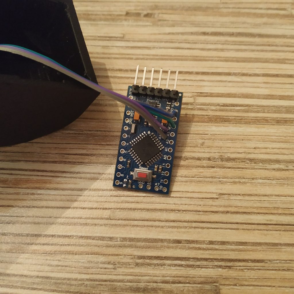
-Solder an ISP header to the Pro Mini board.
-Solder the I2C cable to the board as usual.
-Remove LED from pin 13.
3. Put 4 M3x10mm screws into the KY-023 board. Use nyloc nuts as legs for the board. Solder a 5-wire ribbon cable.


4. Solder KY-023 board to Pro Mini like this:
GND → GND next to pin 2 5v → PIN2 SW → PIN3 VRx → A0 VRy → A1

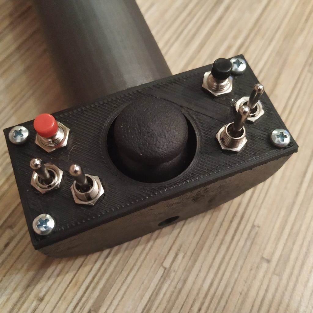
5. Install switches and buttons into the lid as shown on the picture below. Use hot glue to fix them in place.


6. Solder the ground wire to switches and buttons on the lid. Connect it to the GND pin of the KY board.

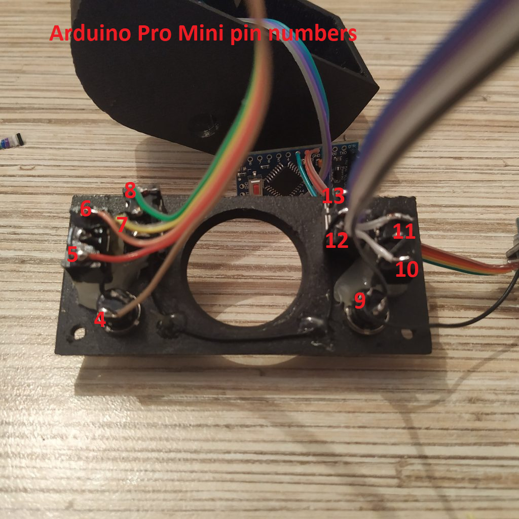
7. Solder 2 5-wire cables to switches as shown on picture below:

8. Solder 5-wire cables to Pro Mini as shown on the picture below:
9. Flash the board with it's firmware, through the ISP header.
Uncomment
#define CALIBRATE
and open the serial console, then check all switches and buttons. If everything works, proceed!
10. Put shrink tube onto the Pro Mini board, and insert it into the throttle frame.


Congratulations, your compact lever is finished!
