Table of Contents
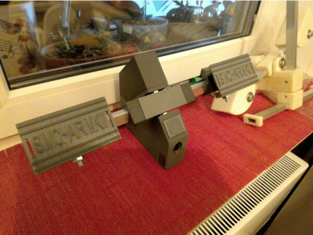
Helicopter pedals
Summary
Special features
- pseudo force trim support for both rubber-bands based and spring-loaded versions (different modes)
- in-flight sensitivity switching support
Components
- Y1 * 300x10x20mm aluminum square pipe
- 2 * 120x10x20mm aluminum square pipe
- 1 * SS495A hall sensor
- 1 * 6x6x4mm or 5x5x5mm square magnet

- 2 * M3x16mm screws for the SS495A mount
- 1 * M3x6mm screw for magnet position adjustment
- 4 * M3x50mm screws for the cover
- 3 * M8x75 bolts
- 2 * M8x16 bolts
- 2 * M8 nyloc nuts
- 6 * 608 bearings (standard skateboard bearings)
- cyanoacrylate to glue SS495A and a magnet
- 1 * ADS1115 ADC
- 2 * LADA2101
clutch pedal spring or similar (1,2mm thick, 11,5mm diameter, 53,7mm height without hooks, ~81mm with hooks when squeezed). Any similar spring with light to moderate tension should work. You can also order them from me in any quantity if you can’t find one at your place. Alternatively, rubber bands can be used.
Downloads
Assembly guide
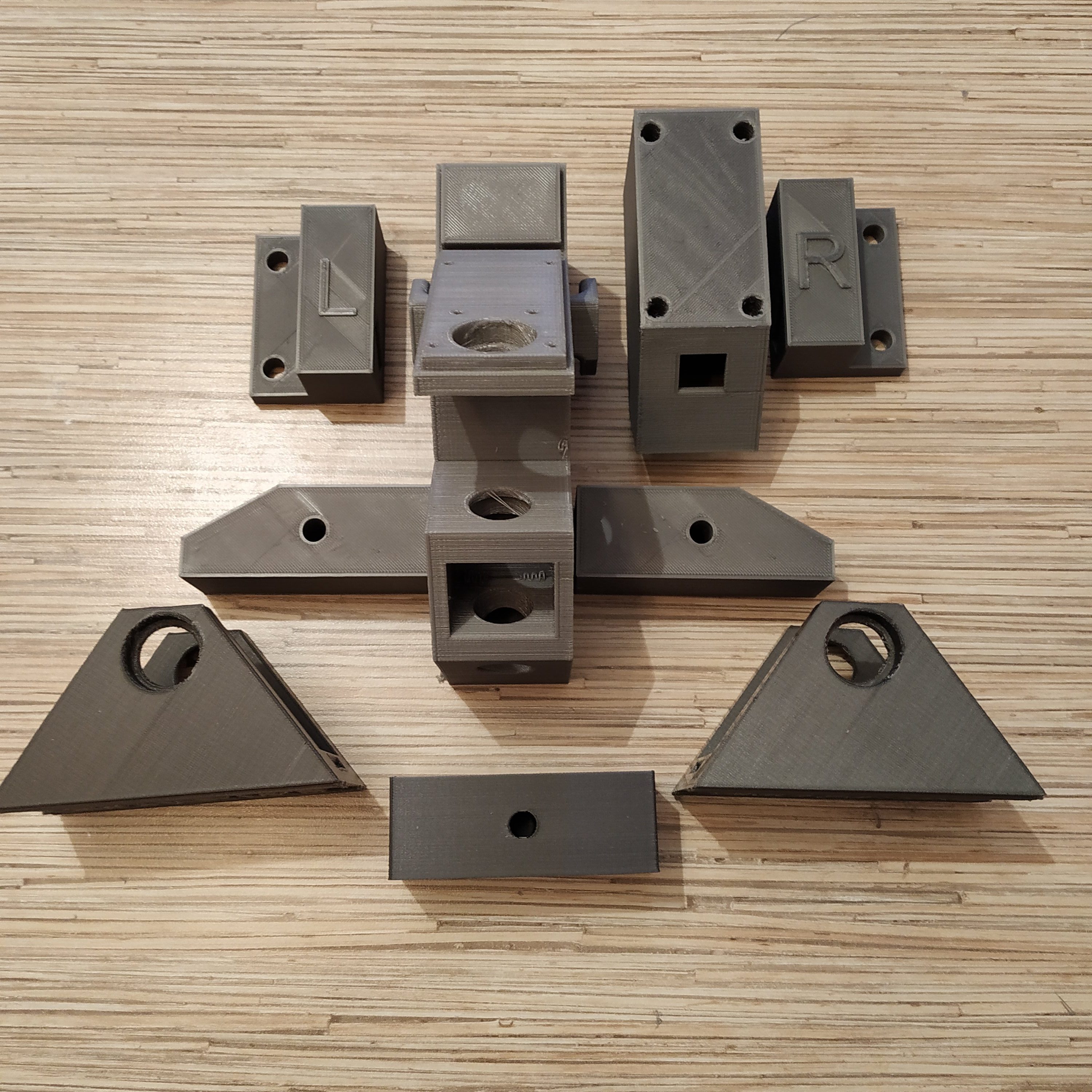
1. Clean all printed parts from supports.
2. Saw off a 300mm and 2x 120mm pieces of 10x20mm square tubing. File sharp edges. Make marks at 130mm from the edge on the 300mm tubing piece.
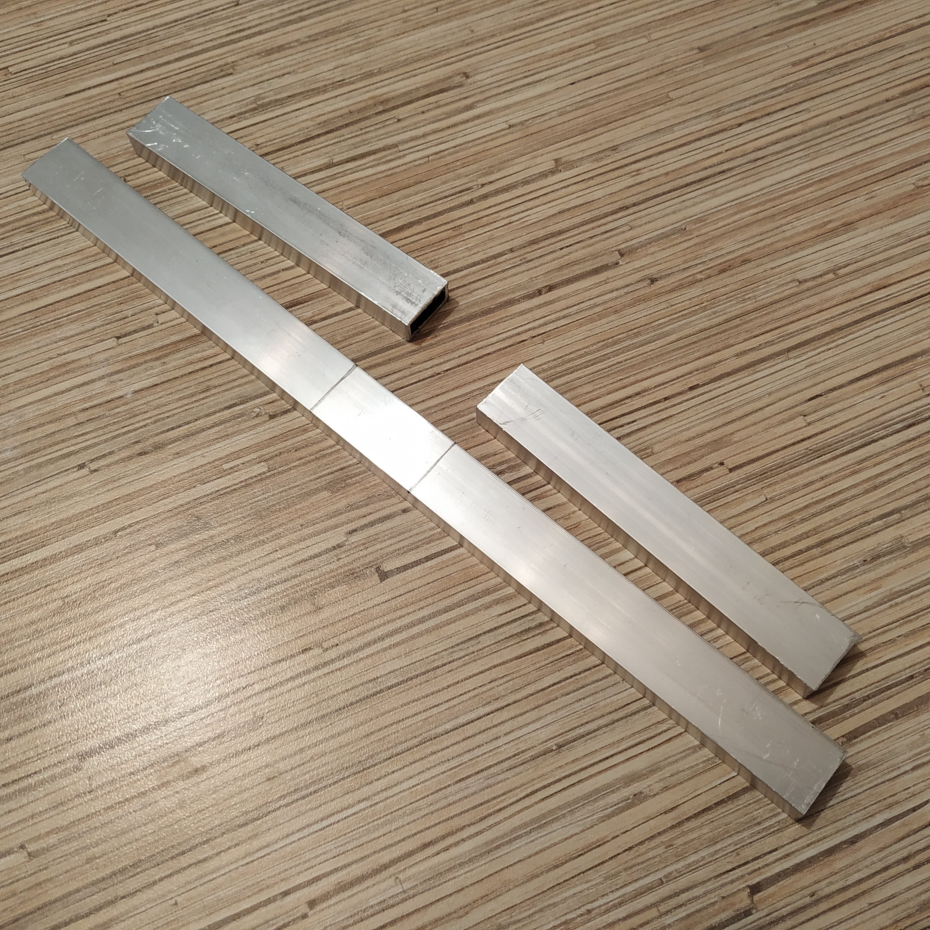
3. Press fit the 300mm piece into the frame carefully so the marks will match frame sides. File as needed. Use 120mm tubing piece as detents.
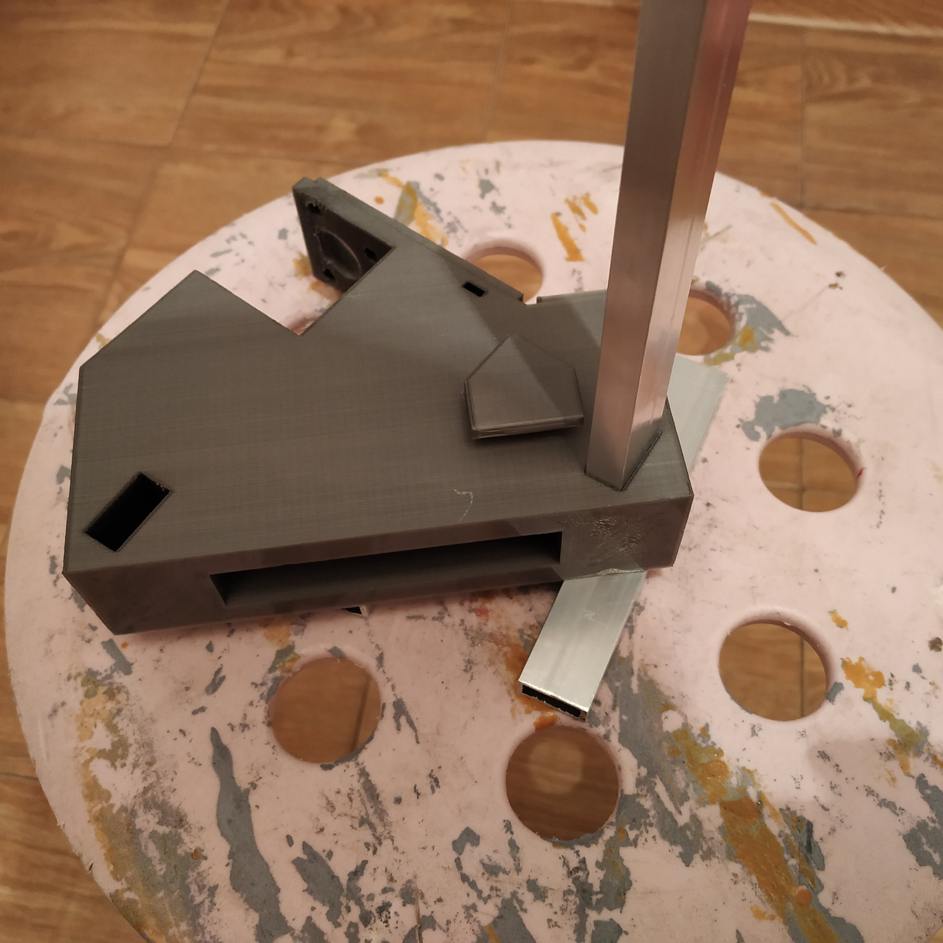
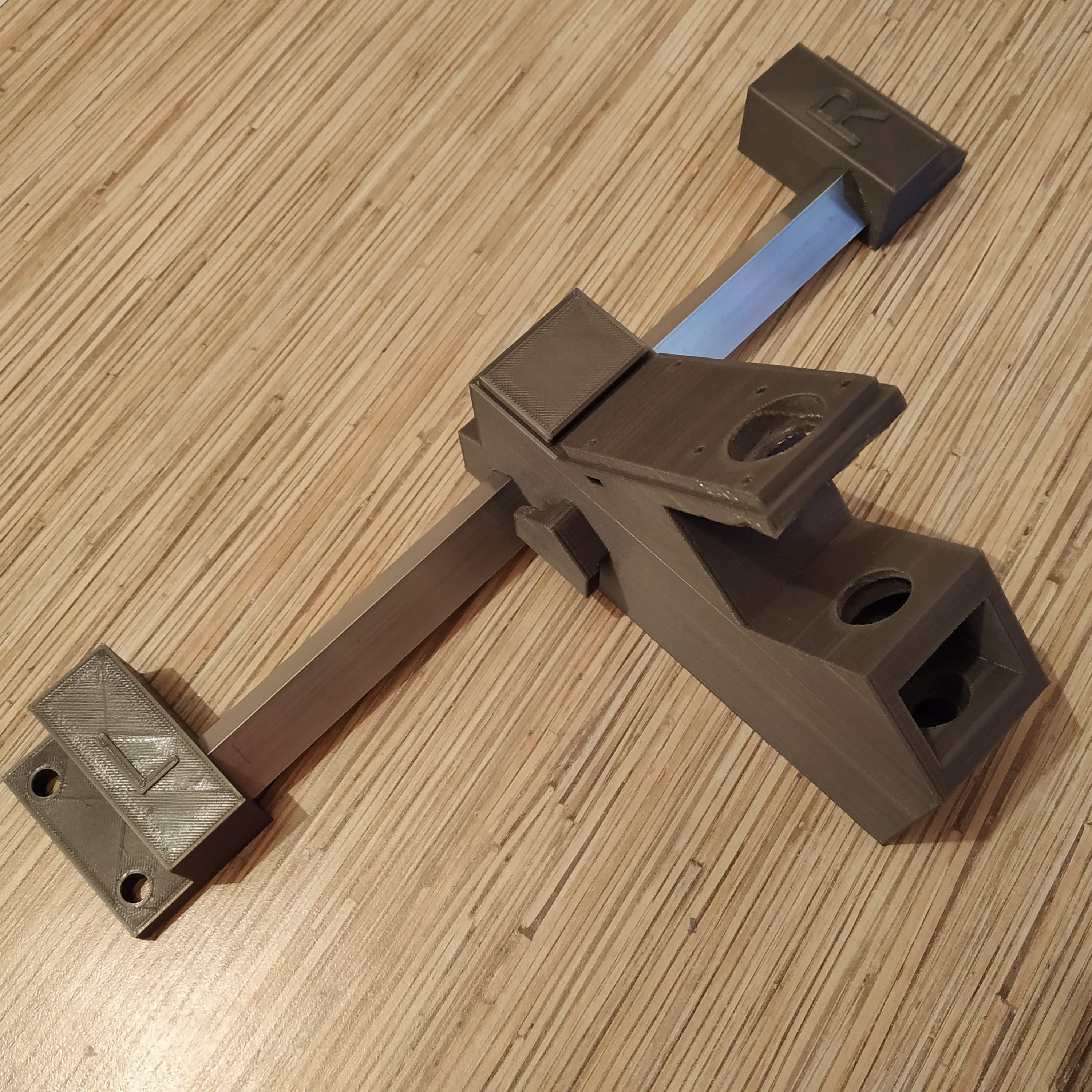
4. Using 120mm pieces as detents, put frame legs onto the 300mm tubing piece.
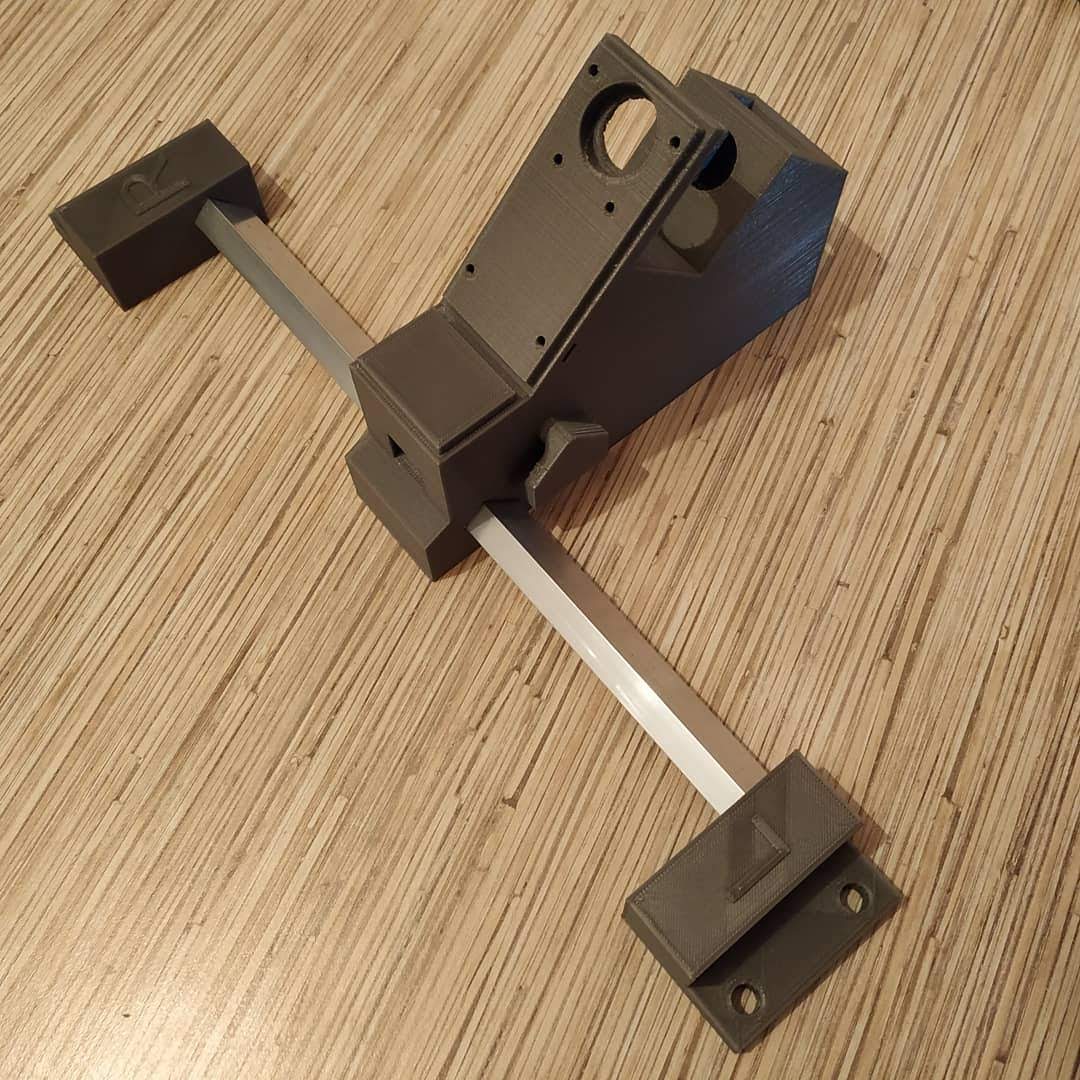
5. Press-fit 120mm tubing pieces into their slots in the rocker part. Position it with its bottom side (as printed) pointing backward (towards the frame).
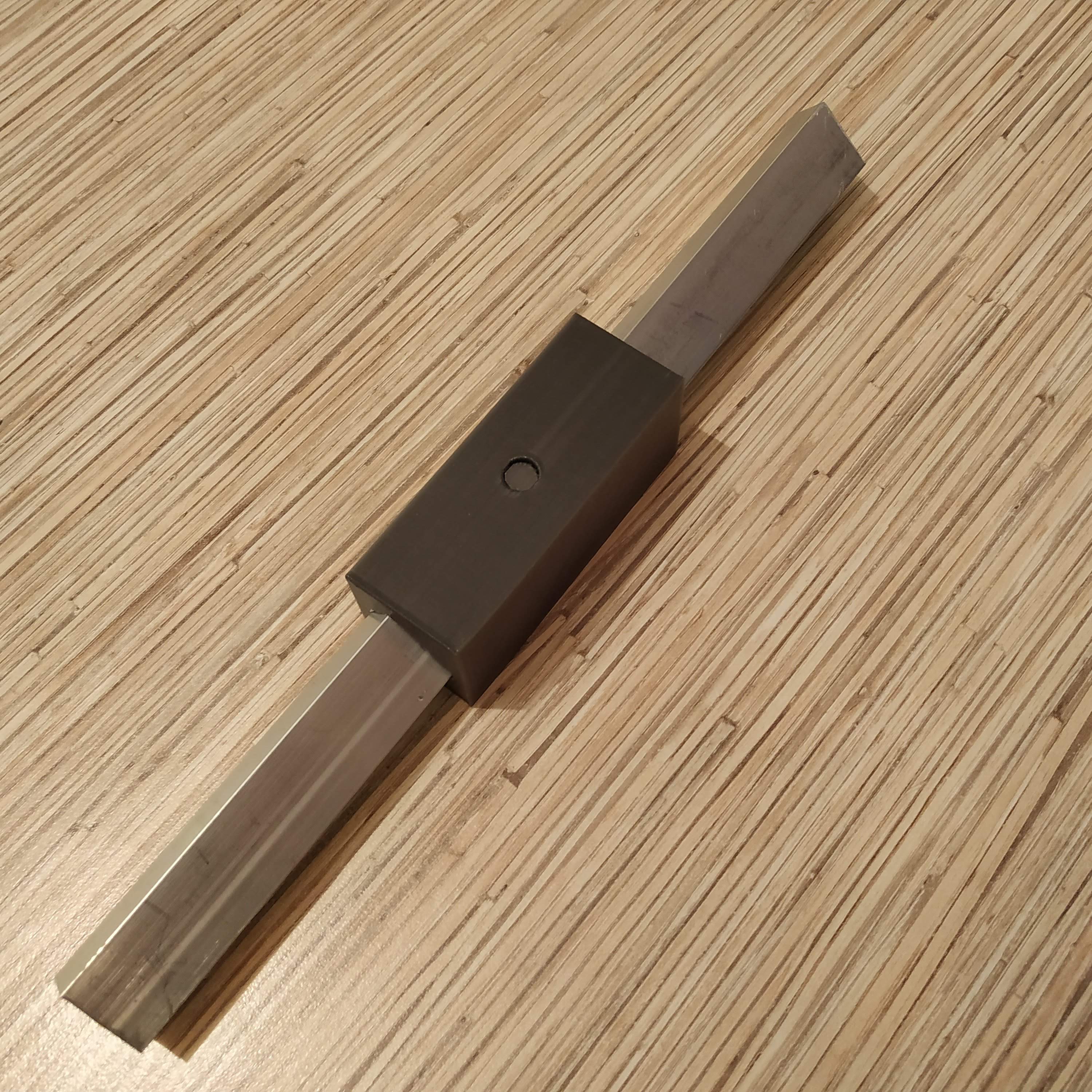
6. Press-fit rubber band holders onto 120mm tubing pieces. I recommend installing these parts regardless of whether you are planning on using rubber bands or springs, as they strengthen the frame additionally.
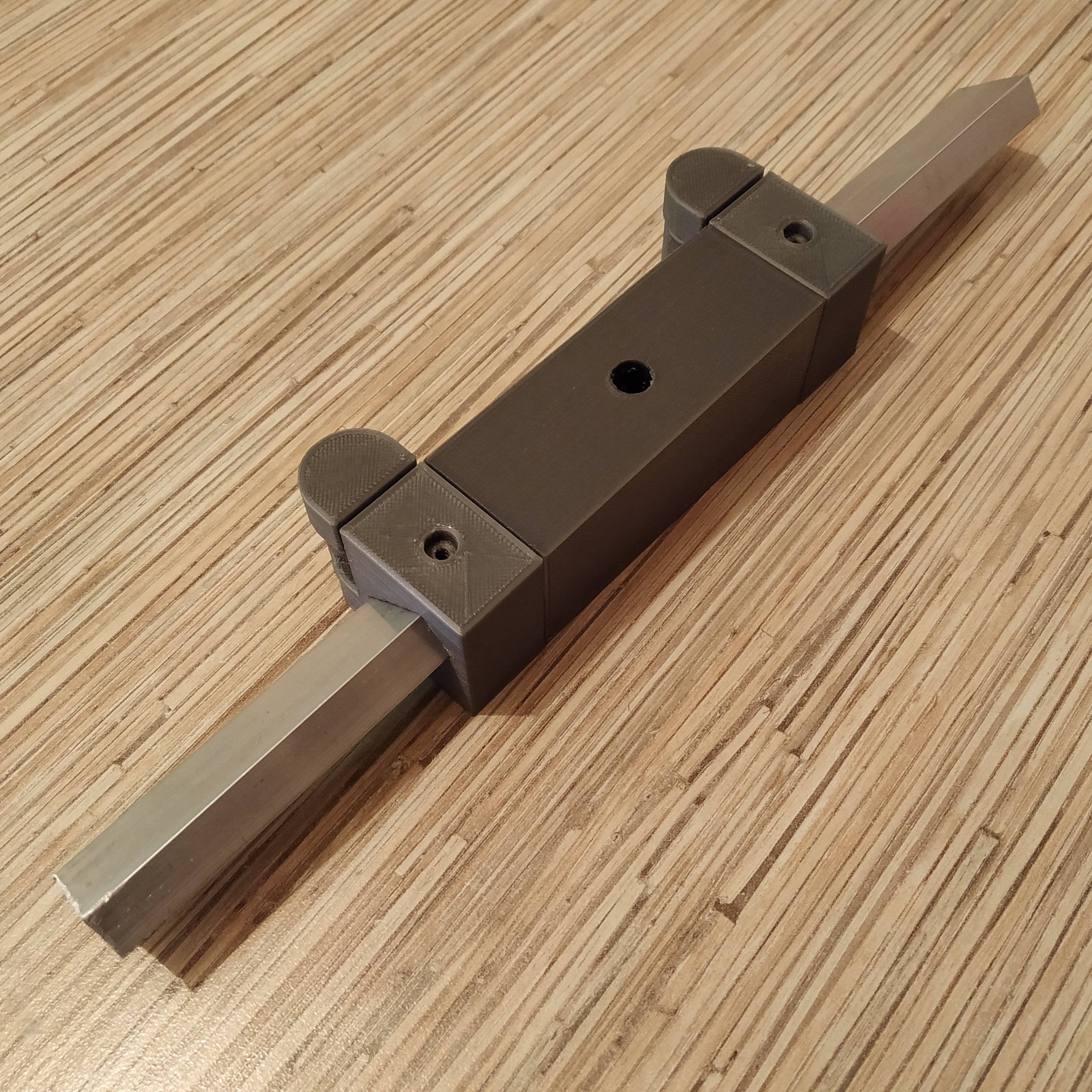
7. Press-fit pedal holders onto 120mm tubing pieces, with their sides, that have been facing the heatbed during printing, facing downwards for a cleaner look.
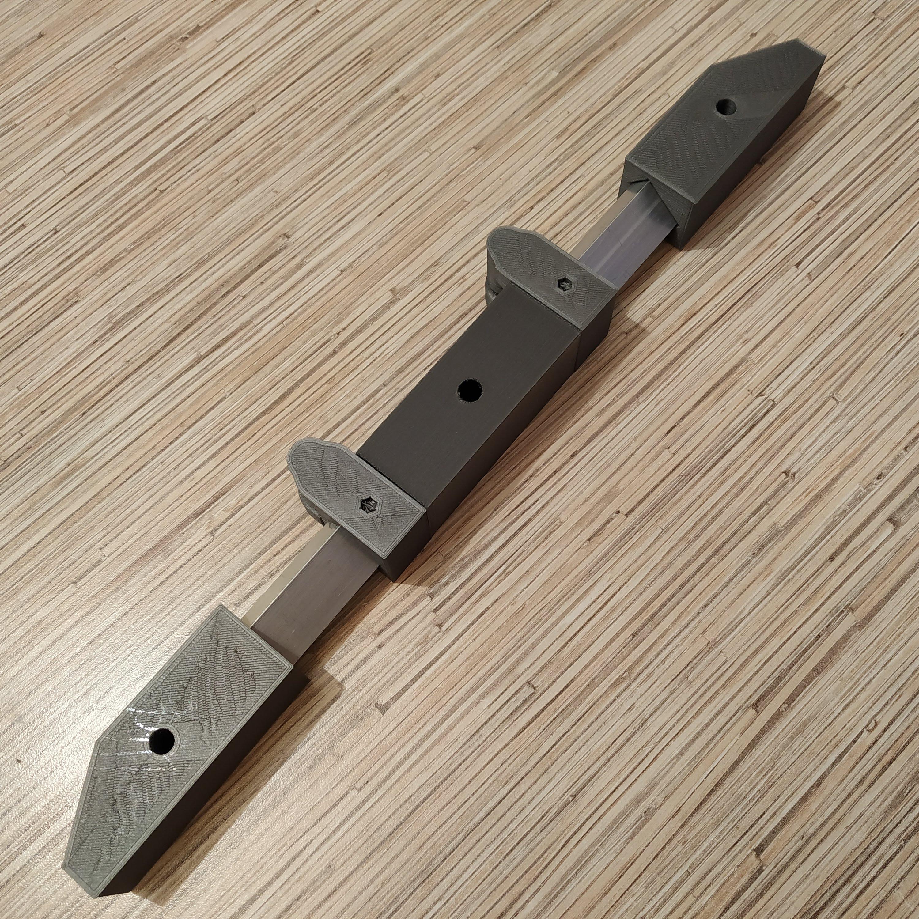
8. It’s time to put pedals onto their holders. Take an M8x75mm bolt and put a bearing, and a nut, onto it. Tighten firmly. We will be inserting this bolt from the top side of the pedal (make sure the pedal is positioned correctly, rubber band holders should be facing upward with their slots. Screw it fully into the pedal holder., press-fitting the upper bearing in the process.
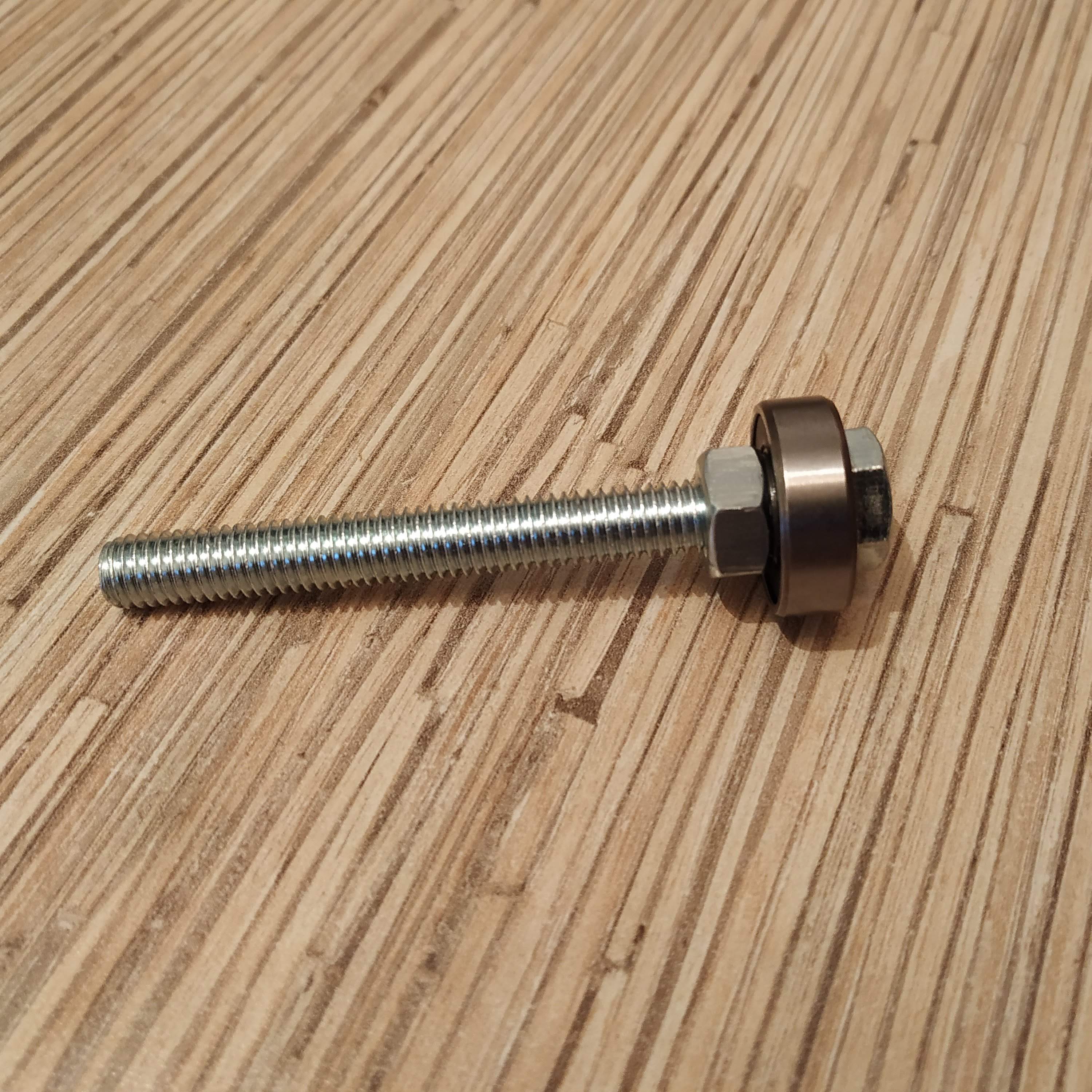
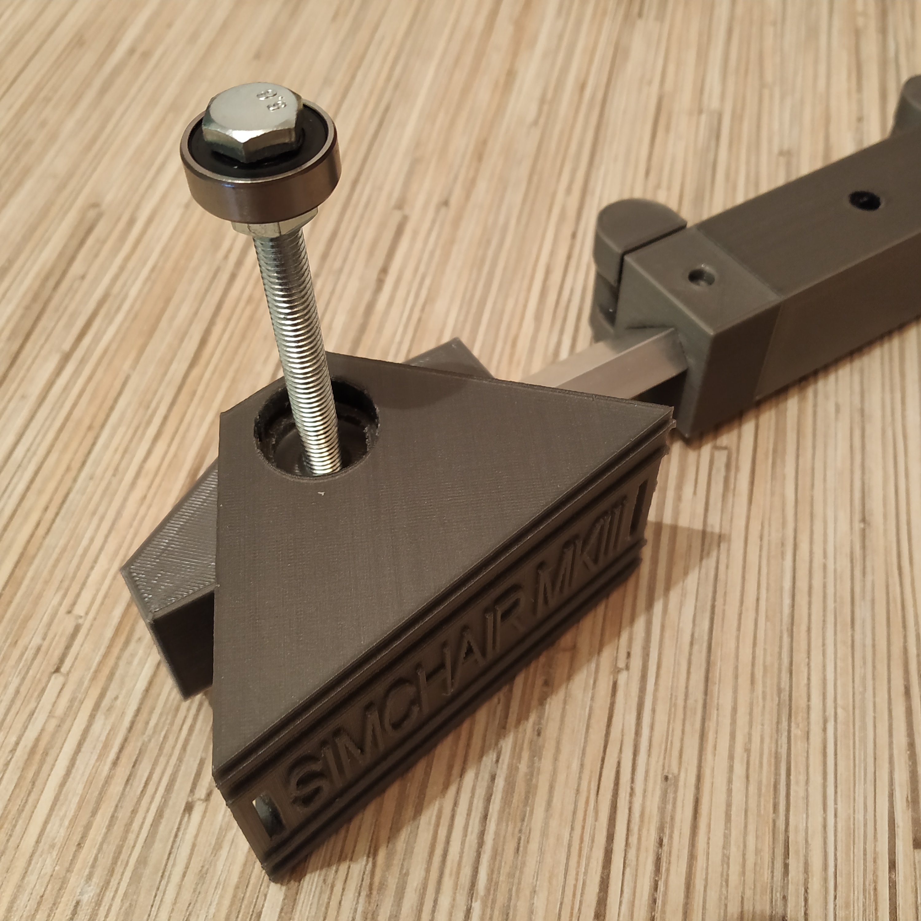
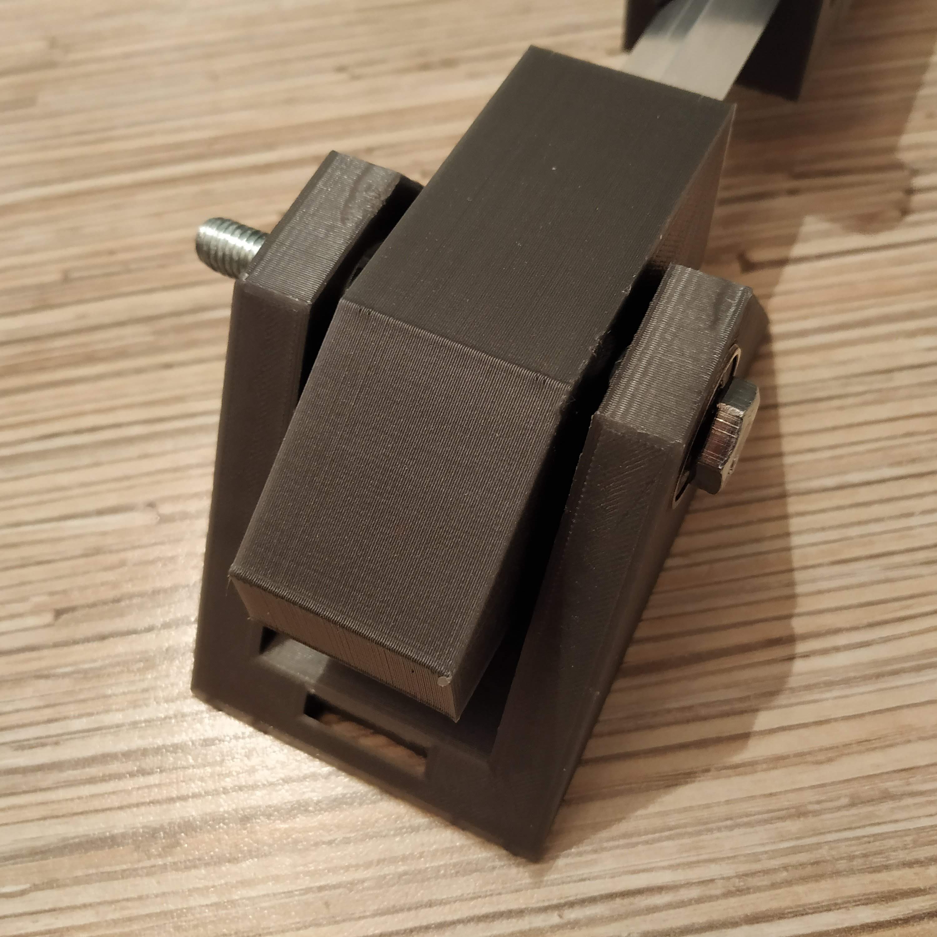
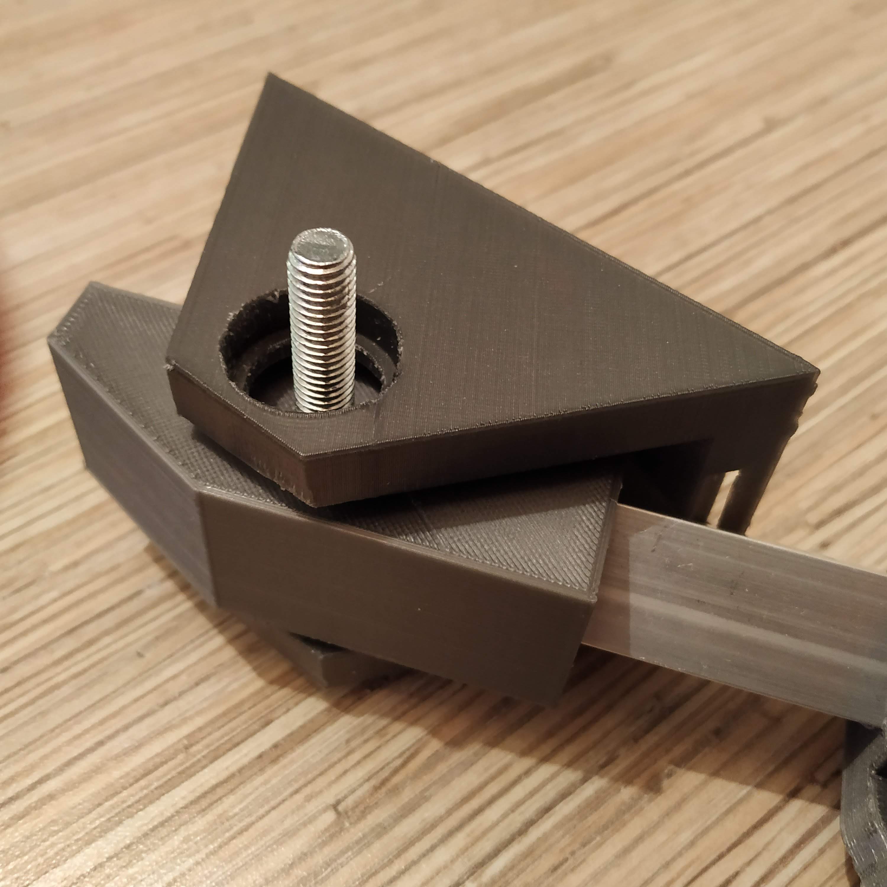
9. Put another nut onto the bolt and tighten it.
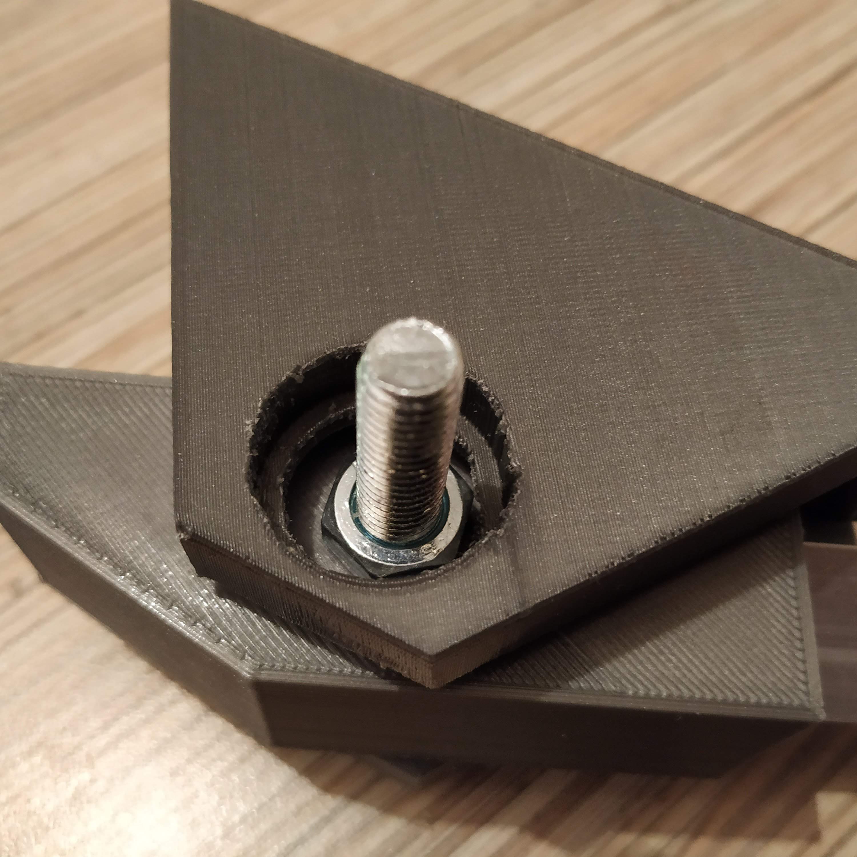
10. Put a spring washer onto the bolt.
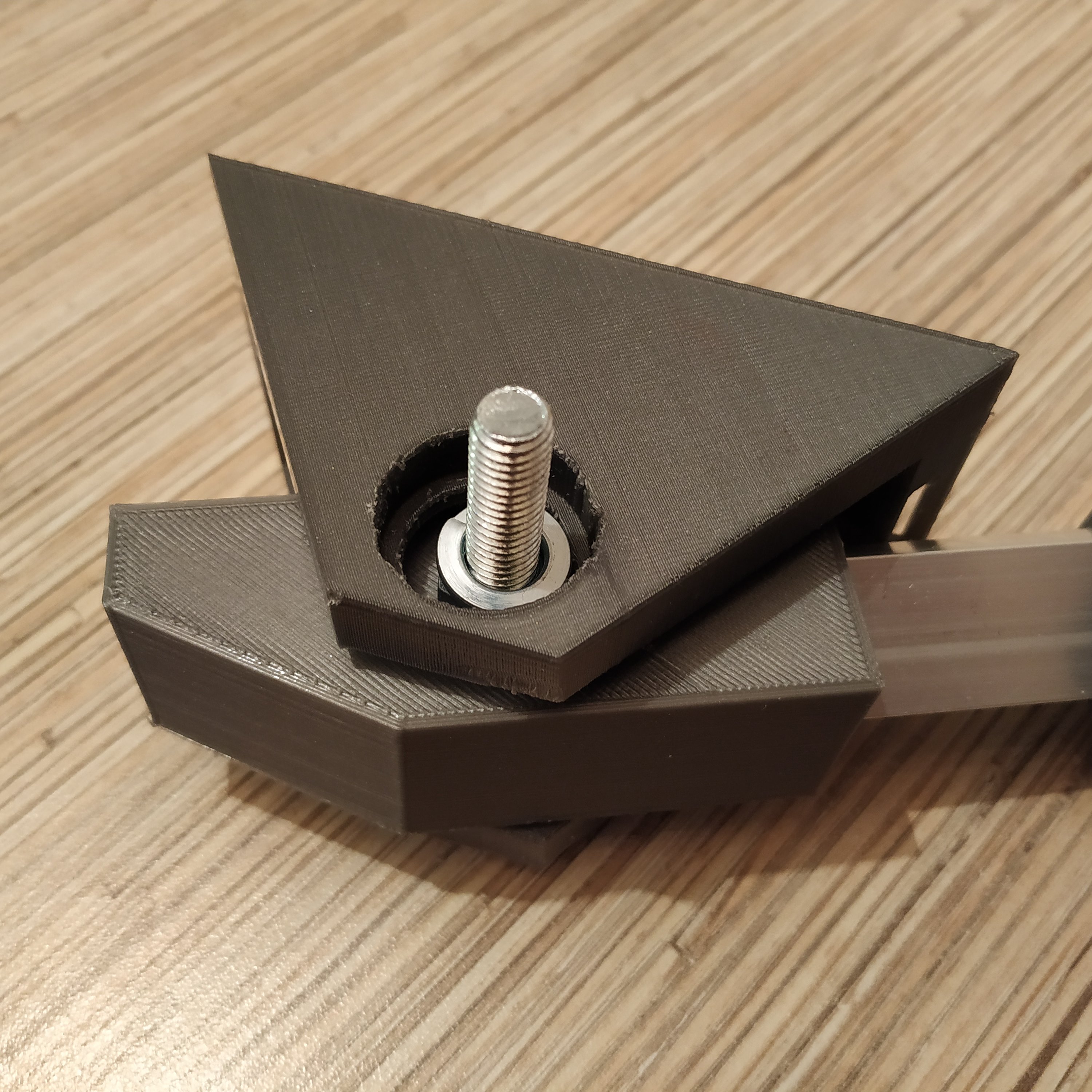
11. Put another bearing and a nut onto the bolt, and press-fit the bearing while tightening the nut. Tighten everything firmly, there should be no backlash.
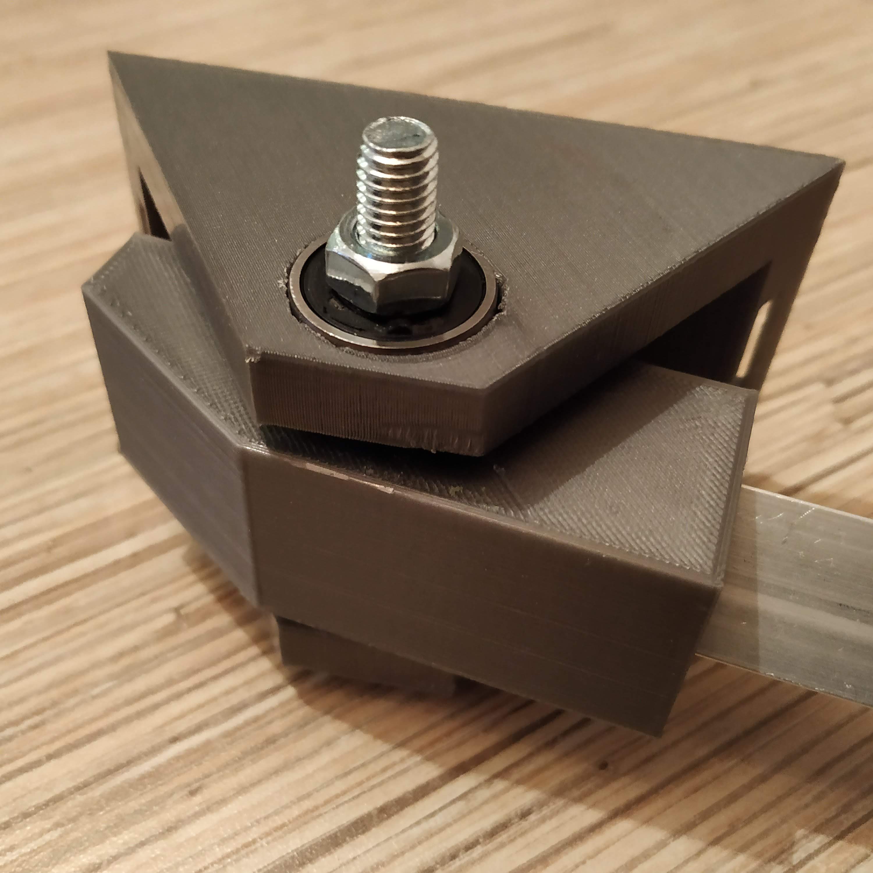
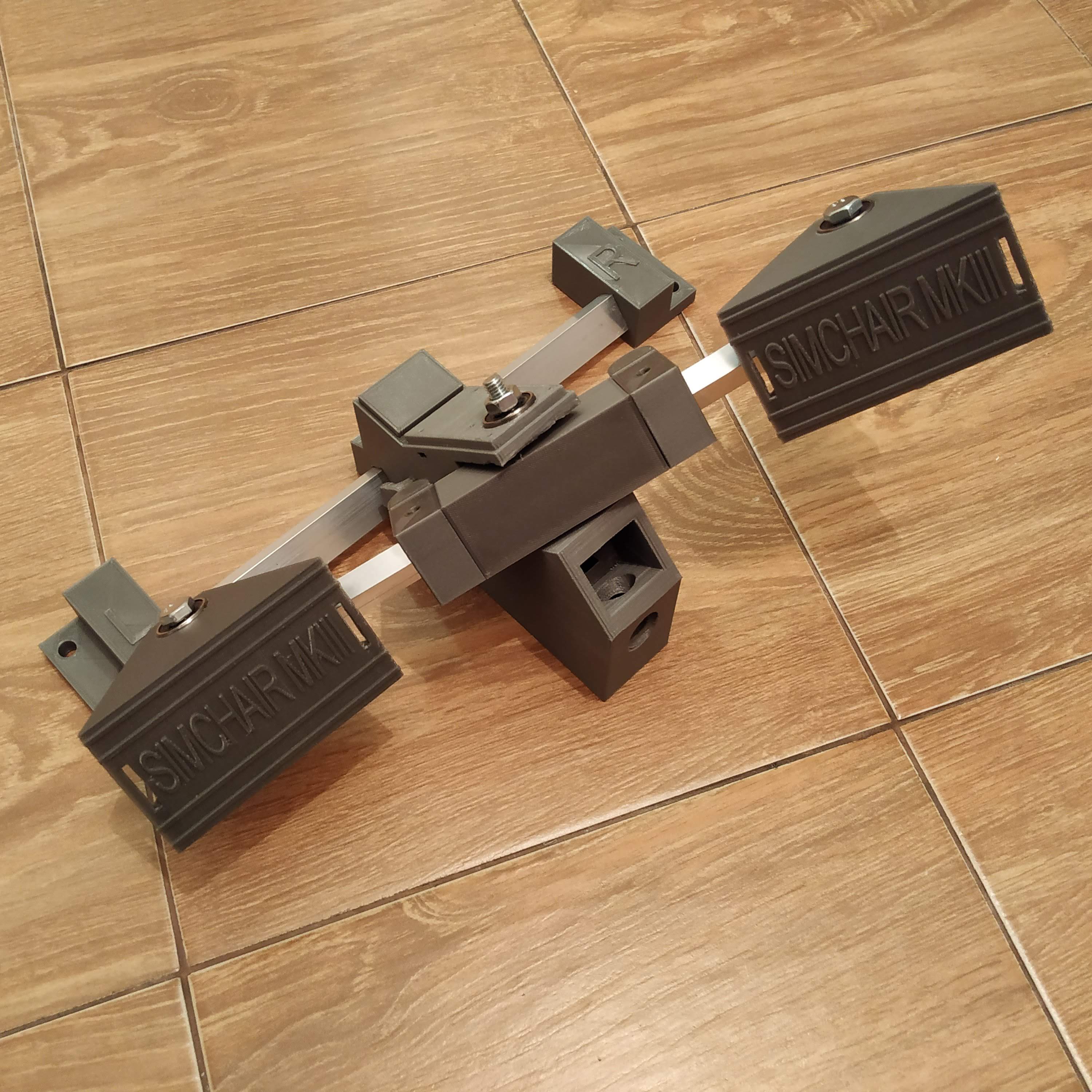
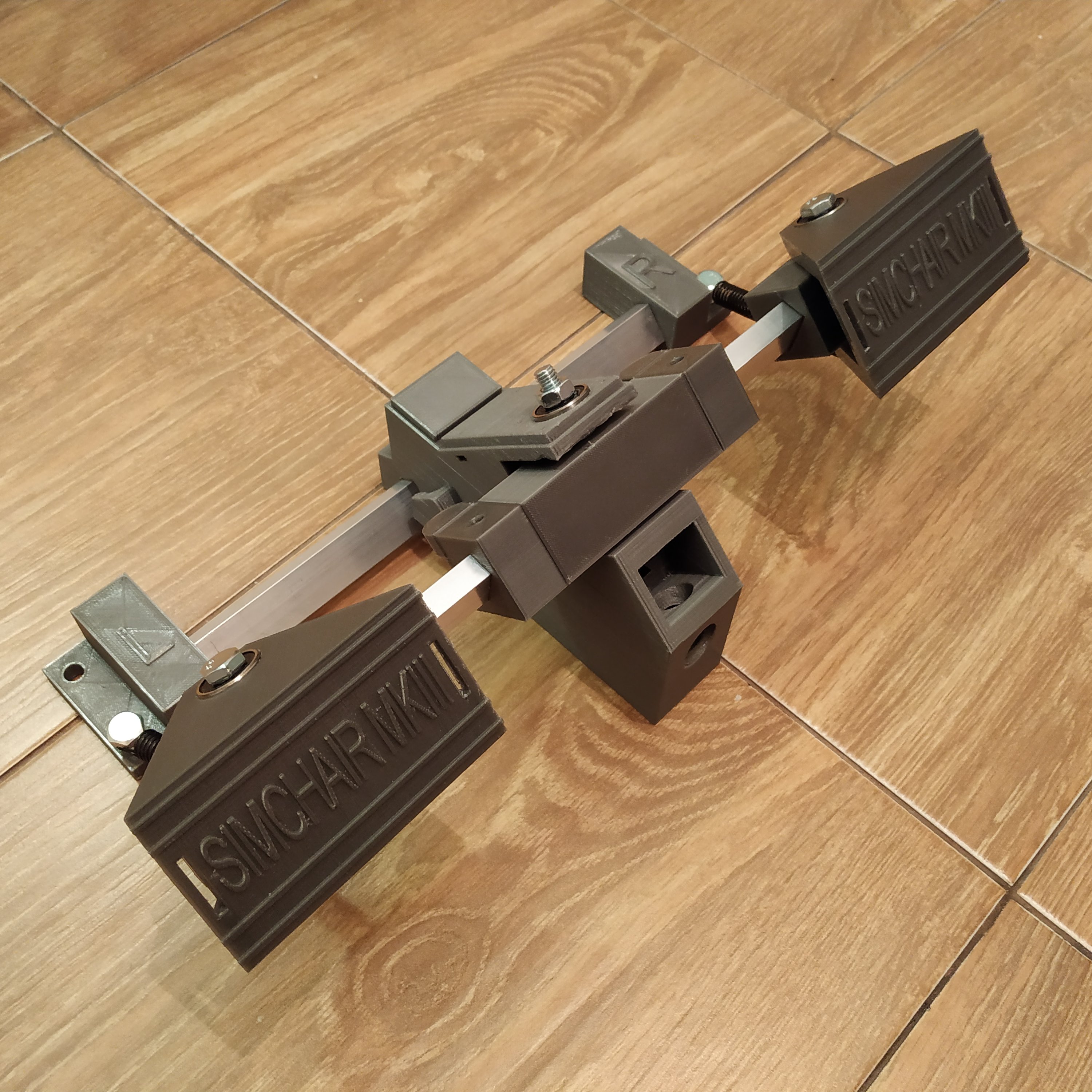
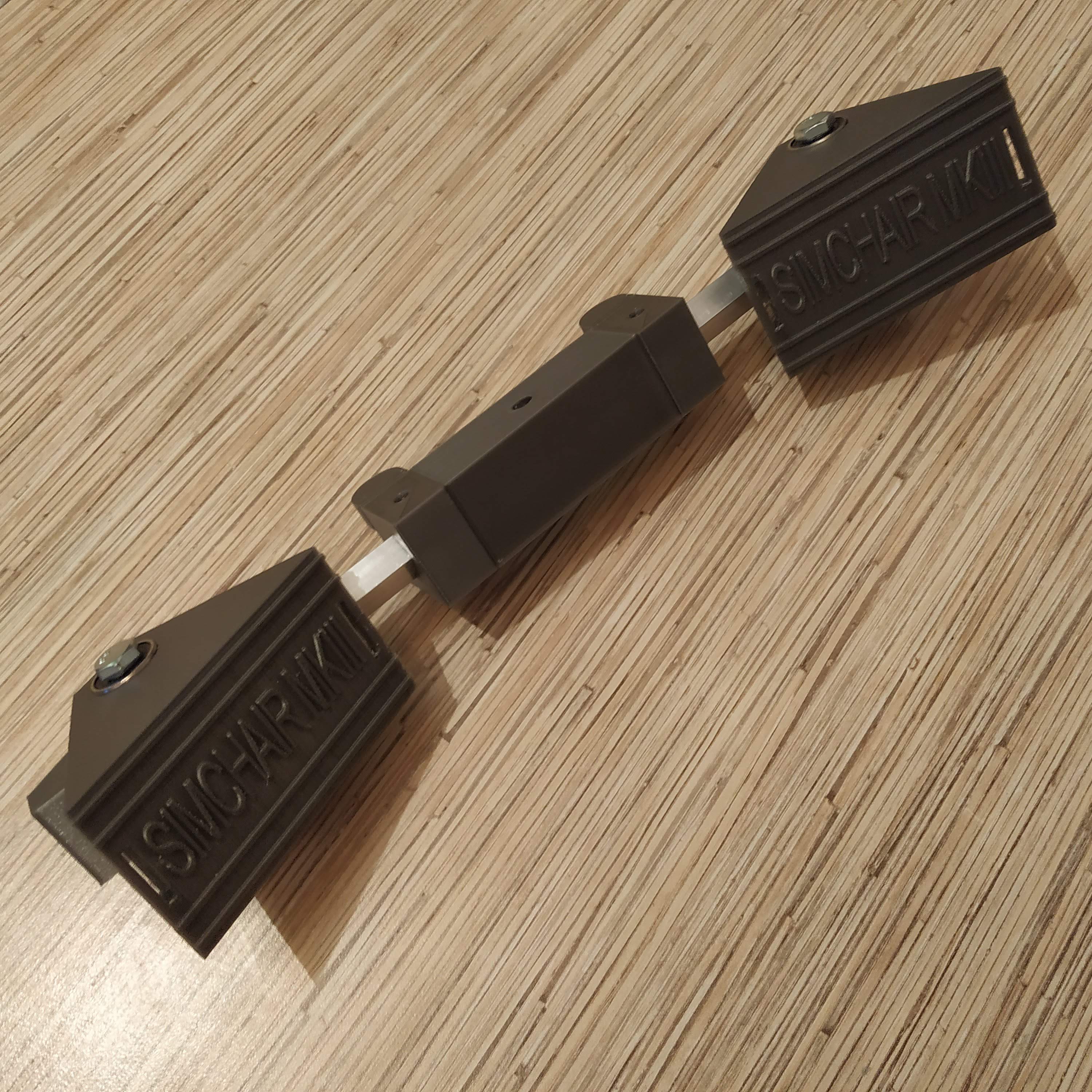
12. Repeat steps 8-11 for the 2nd pedal. After you’ll finish, the result should look like that:
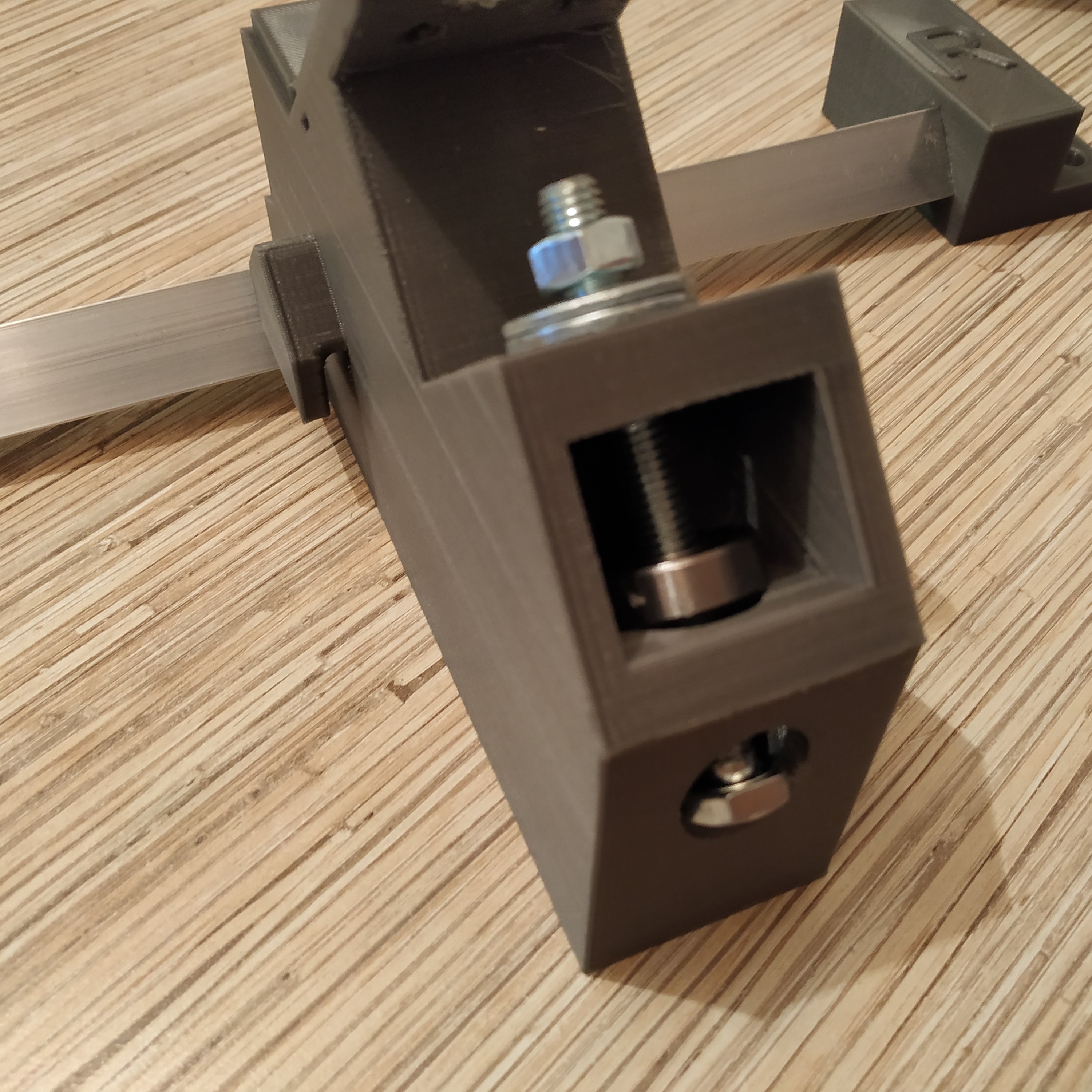
13. Press-fit the lower bearing of the main frame into its slot. To do it, use a 3rd M8x75mm bolt, 2 reinforced M8 washers, and a nut, as shown in the pictures below:
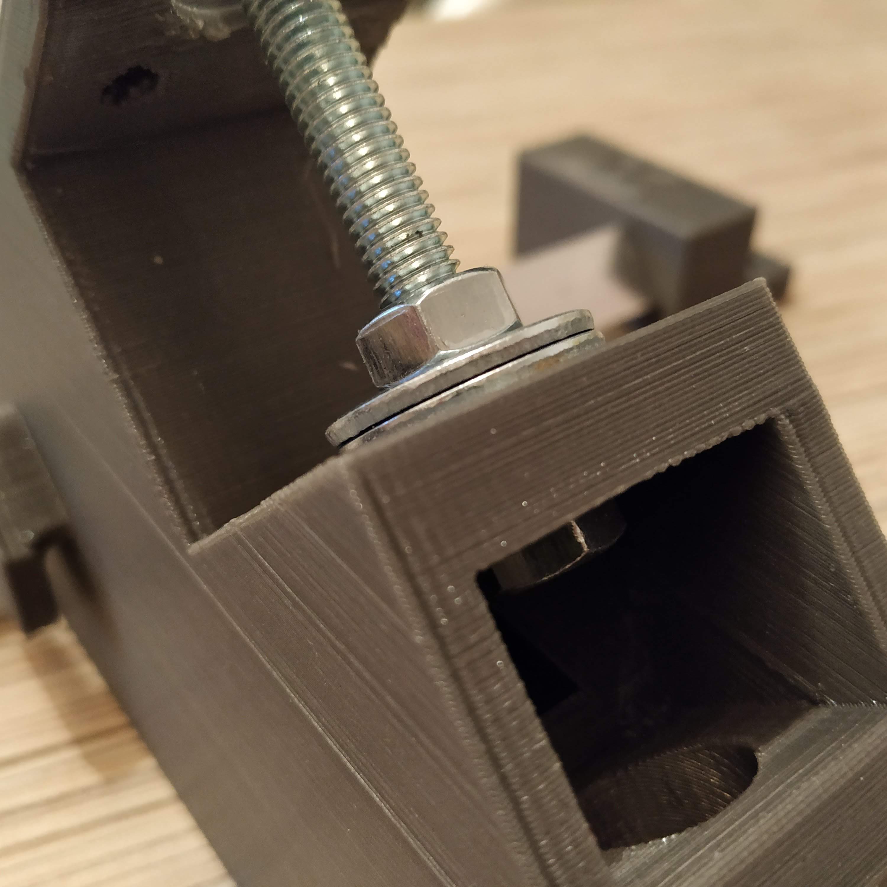
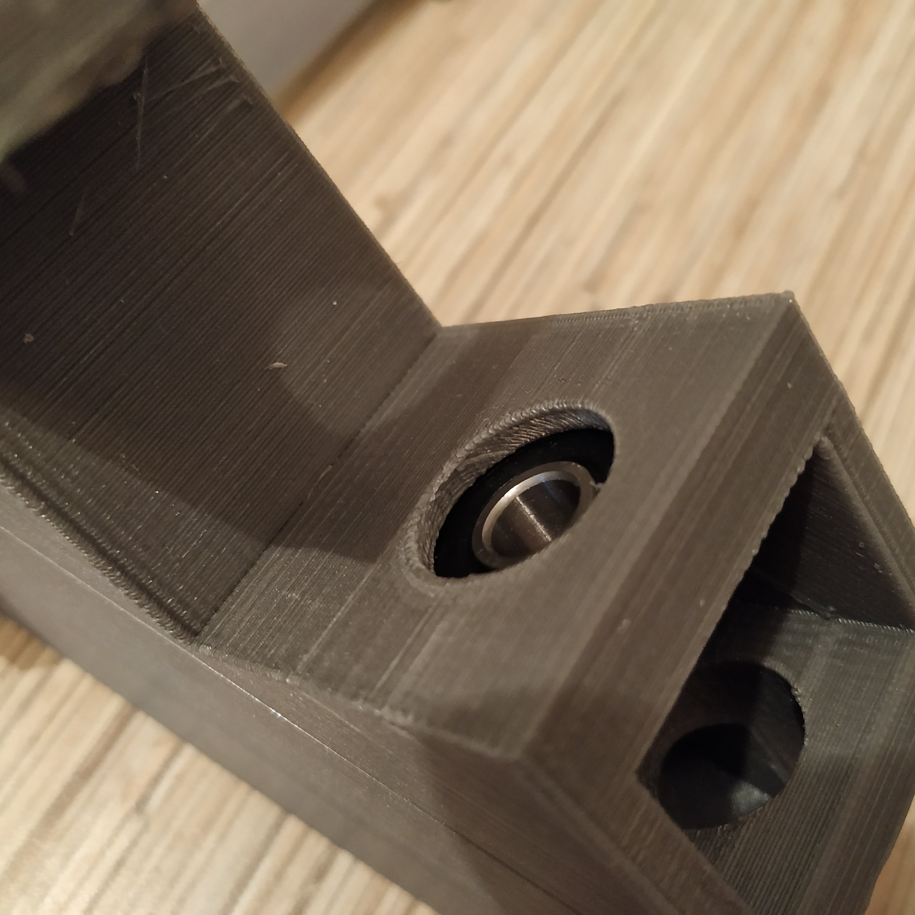
14. Press-fit M3 nuts into their slots in the frame.
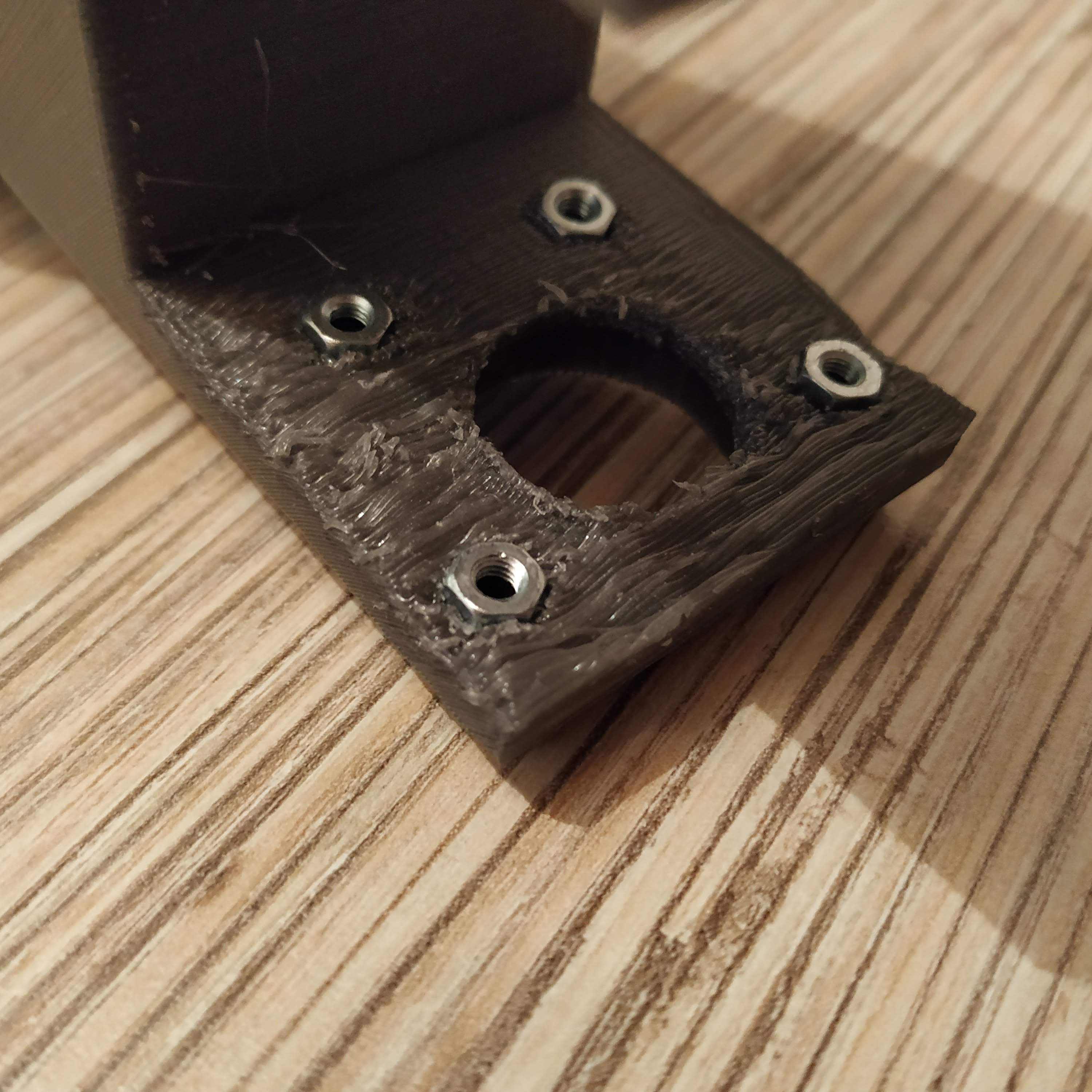
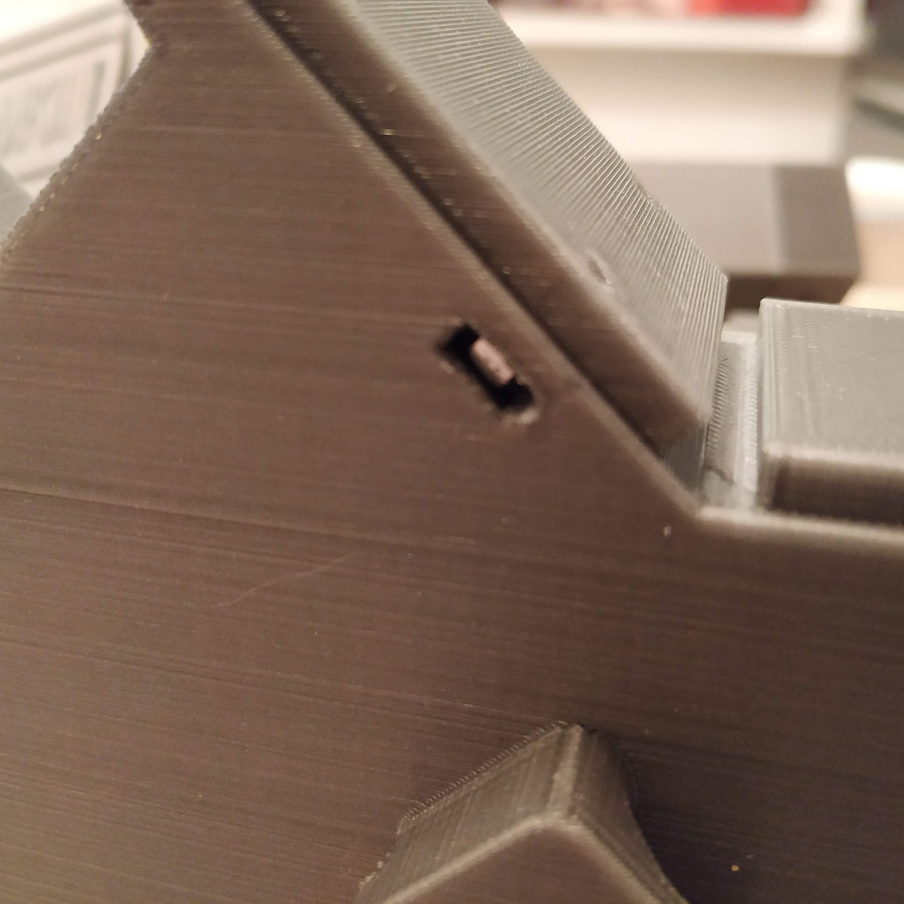
15. Put a bolt through the bearing we have just installed, add a nut and put the rocker assembly on.
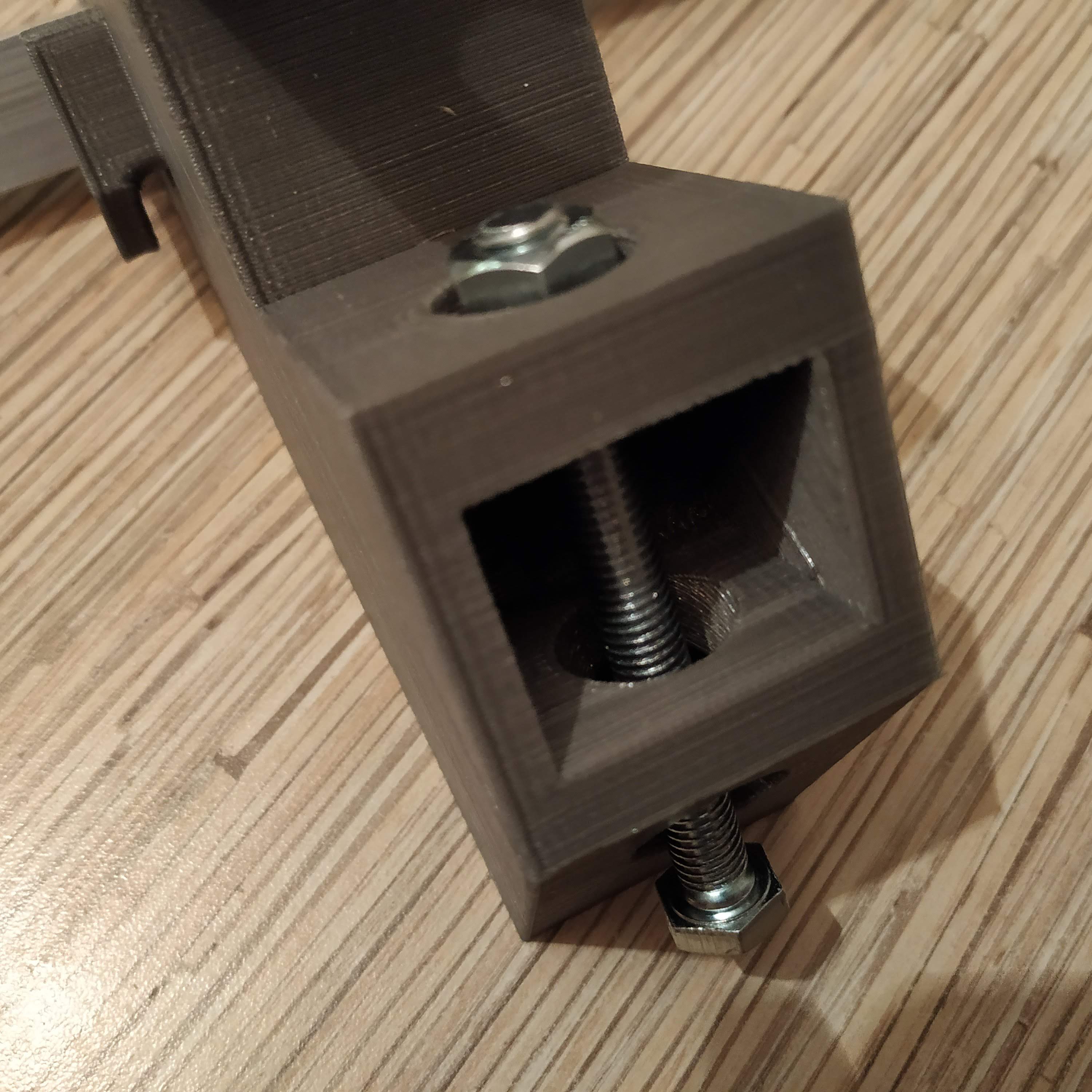
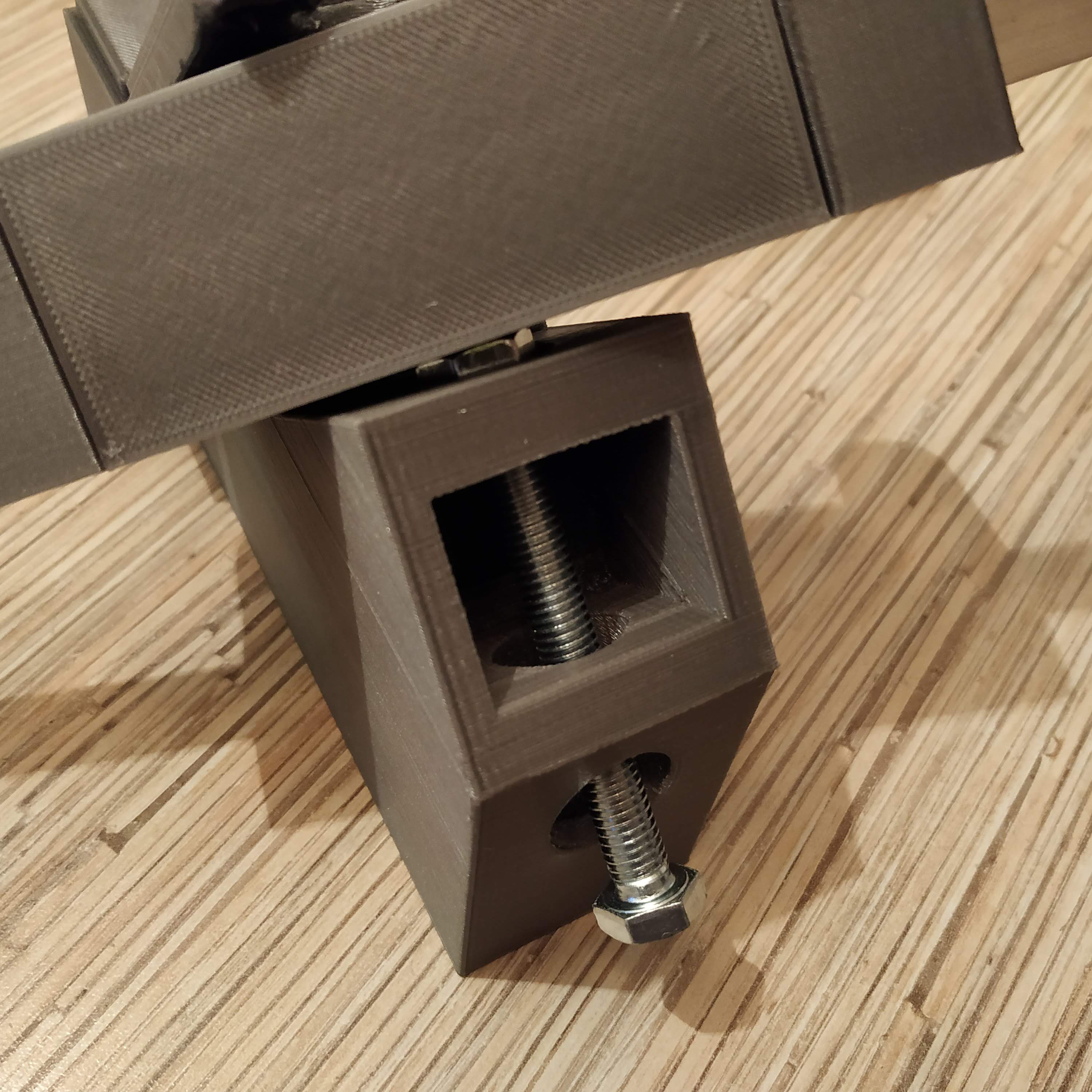
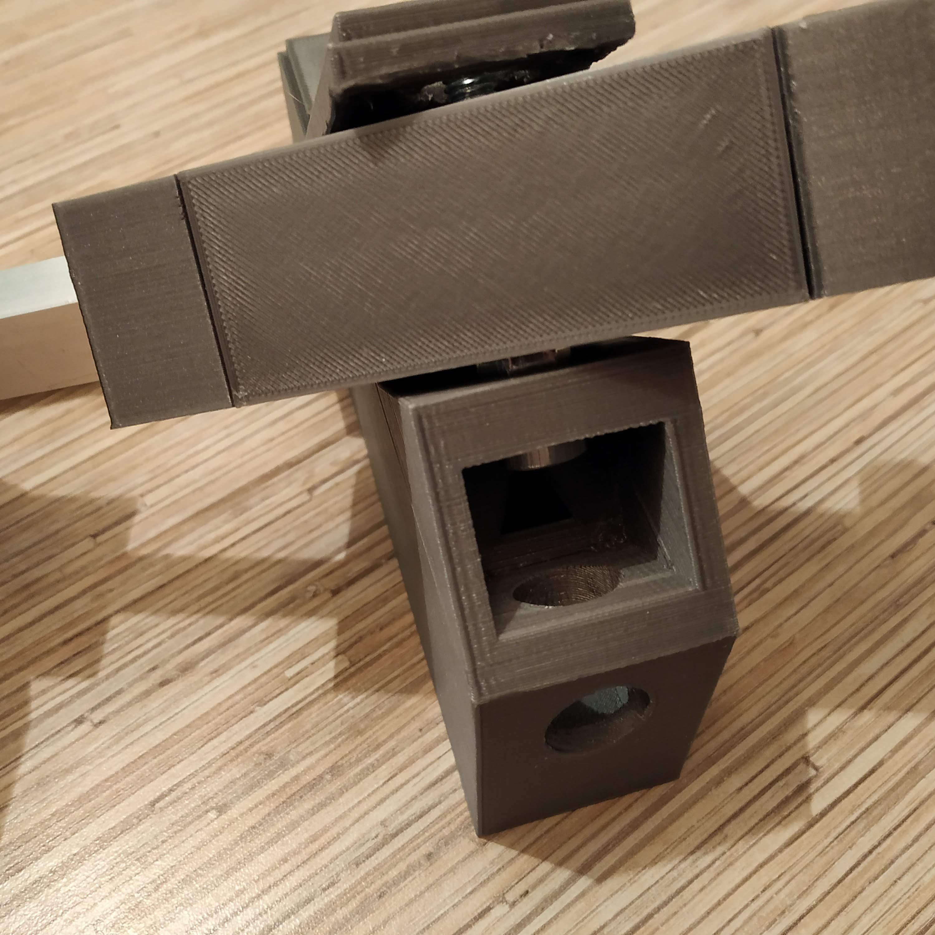
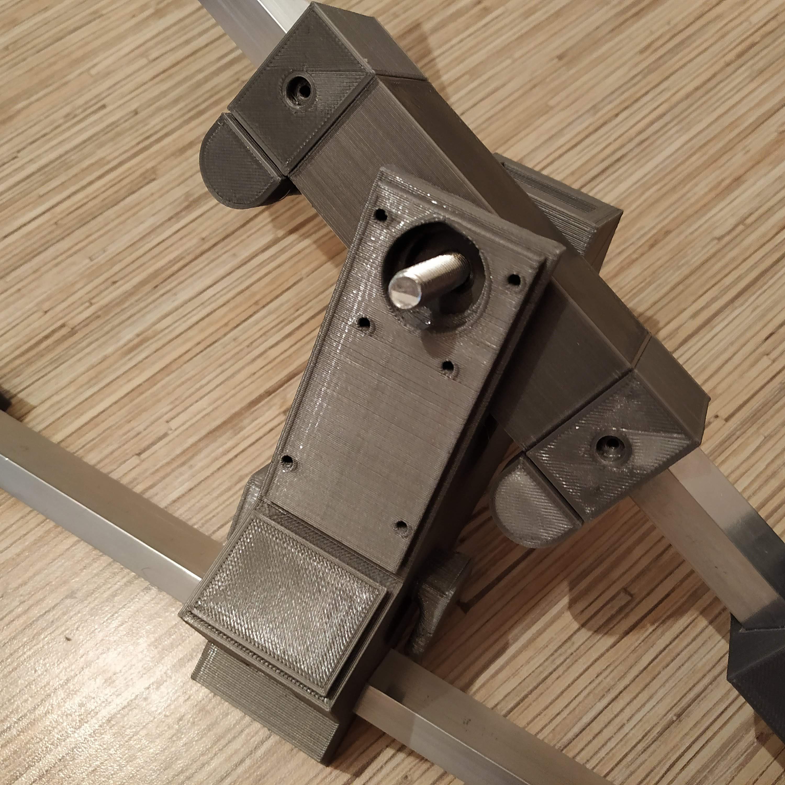
16. Put a nut onto the bolt and tighten it, add a spring washer.
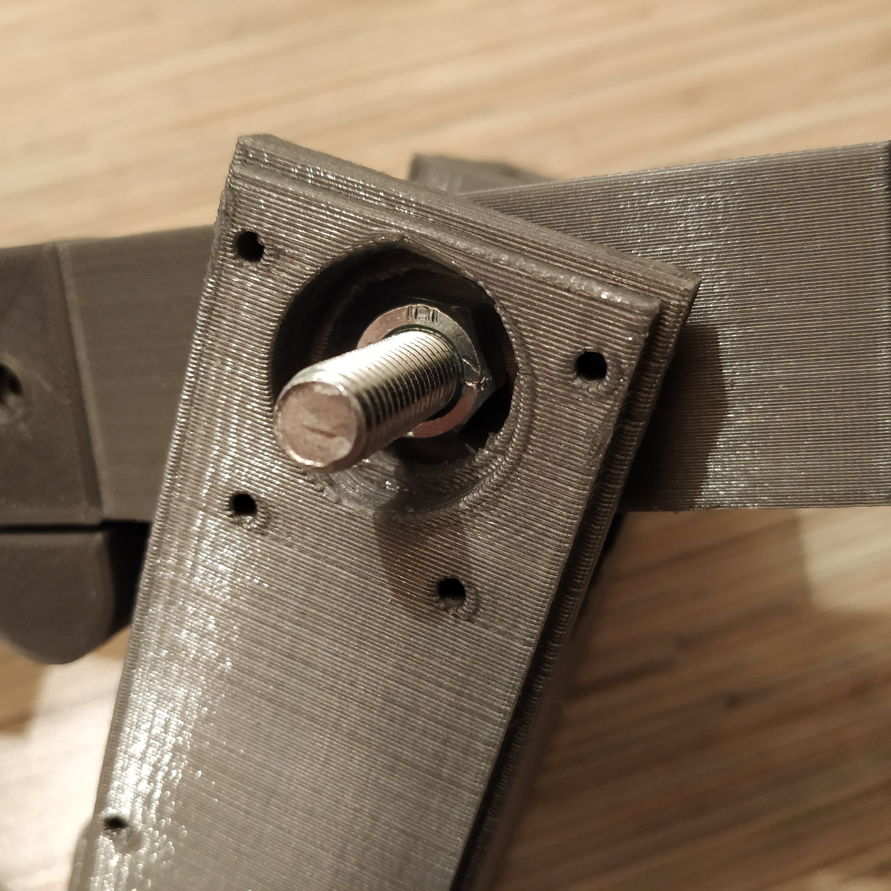
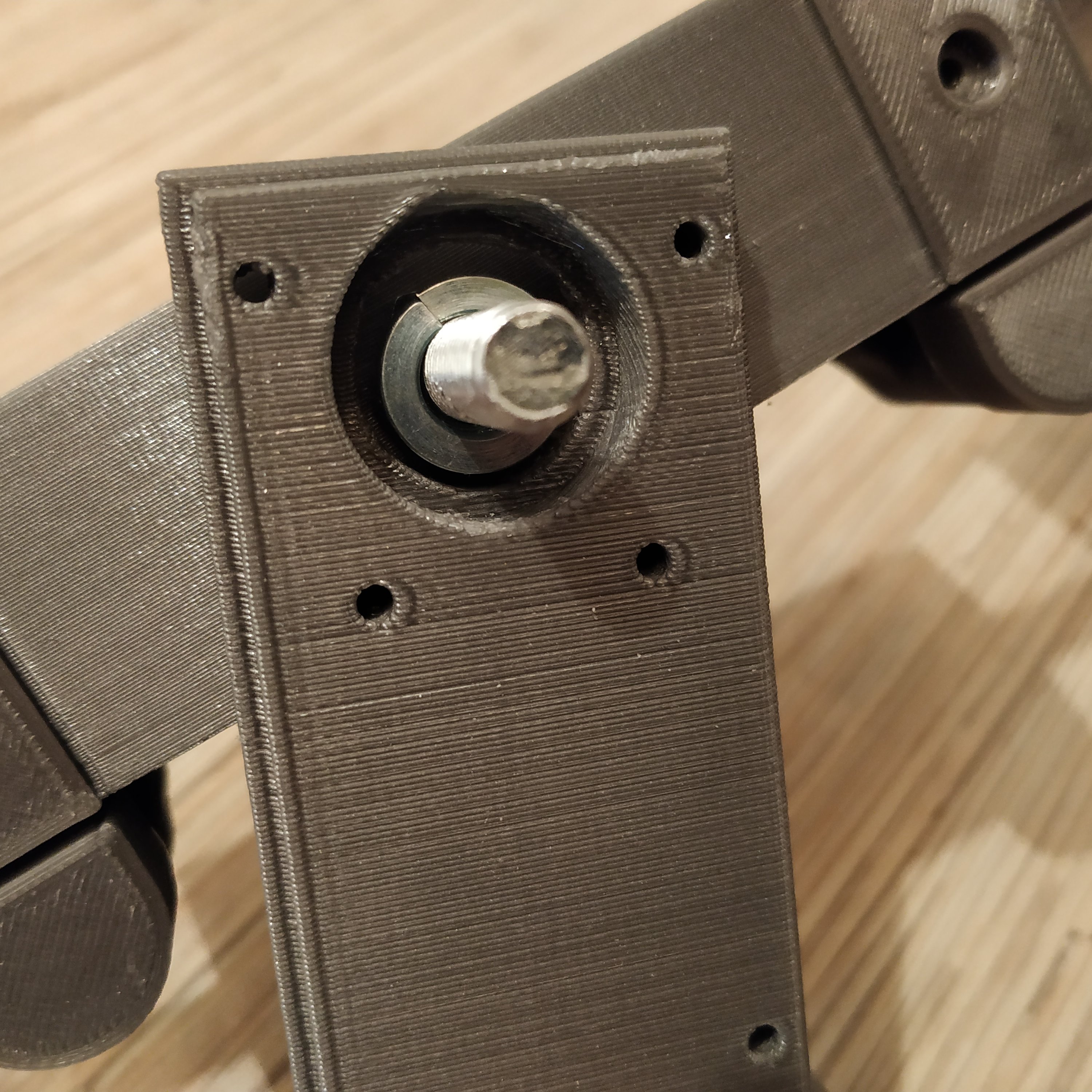
17. Put a bearing onto the bolt, add a nut and tighten it firmly, press-fitting the bearing into its slot. Put something between the rocker and the frame so the frame won’t bend! Check there’s no backlash in the assembly.
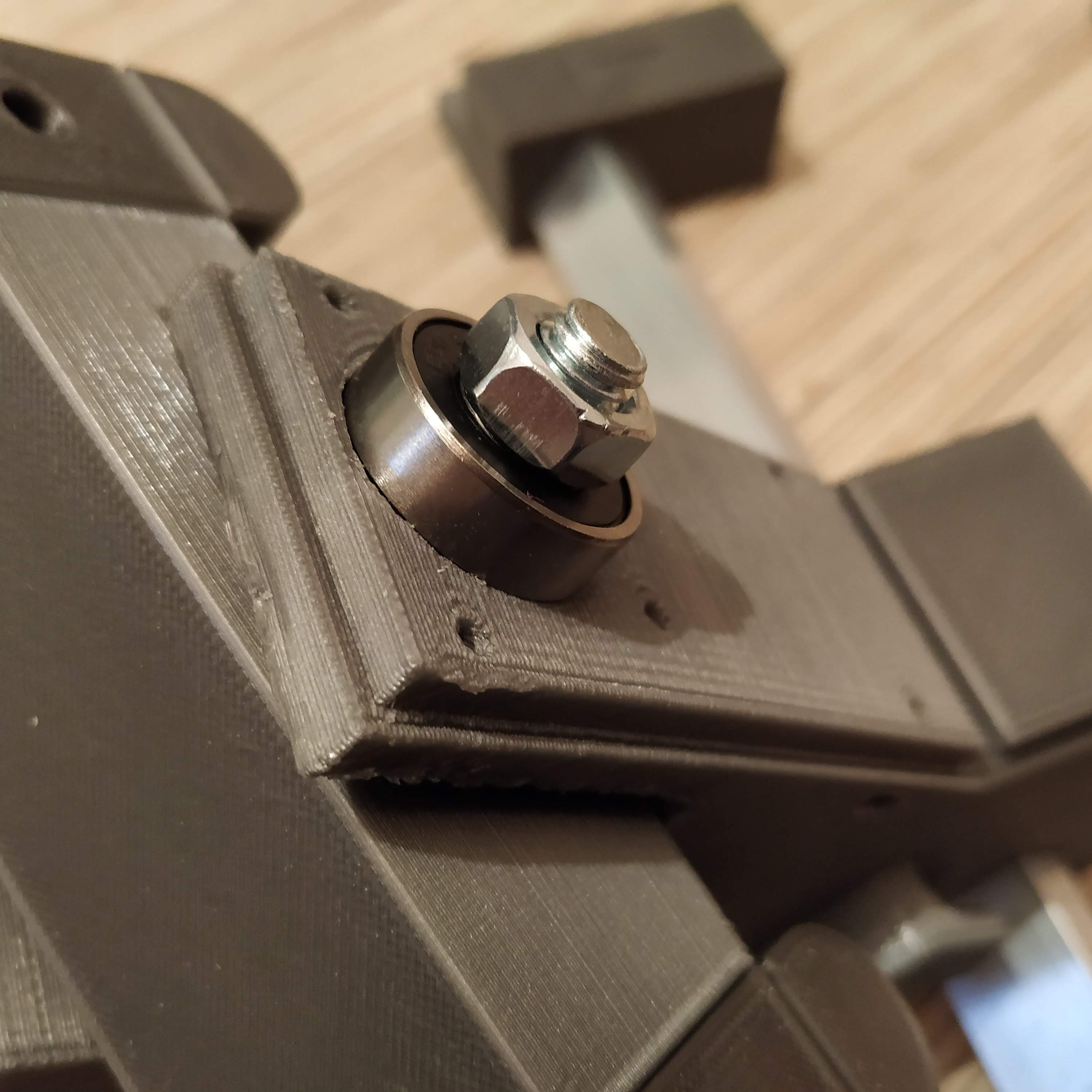
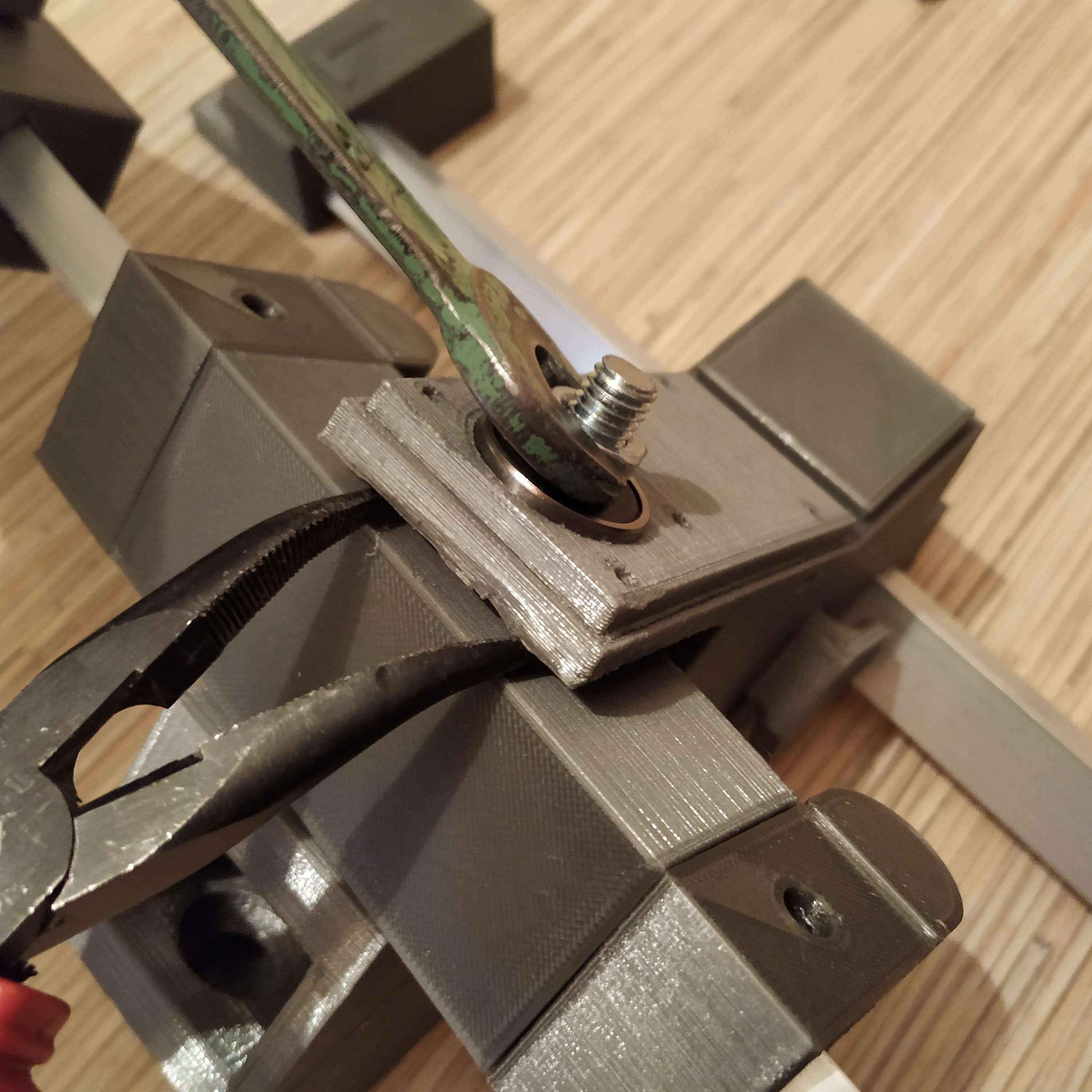
18. Insert 2 M8x16mm bolts into frame legs as shown in the following picture:
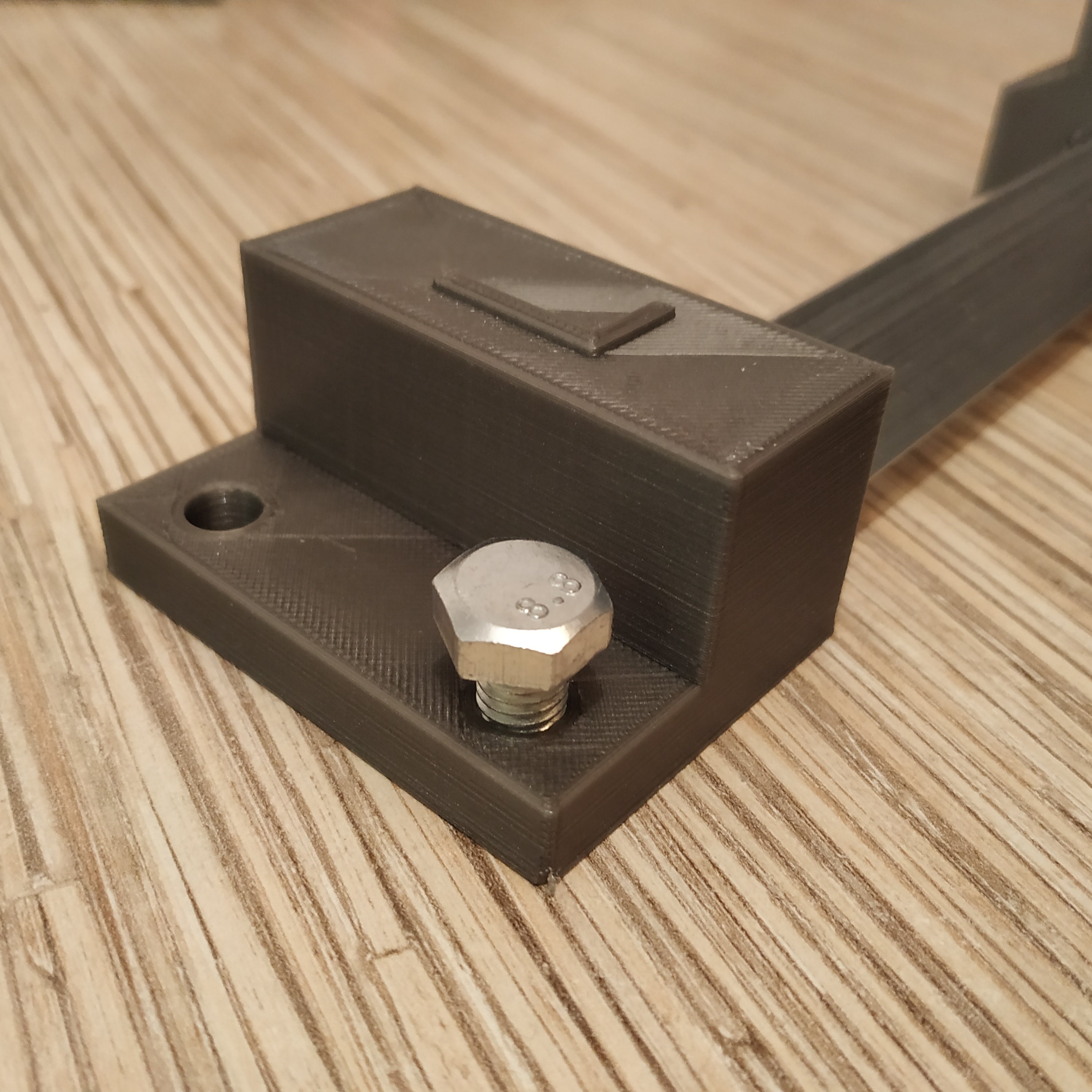
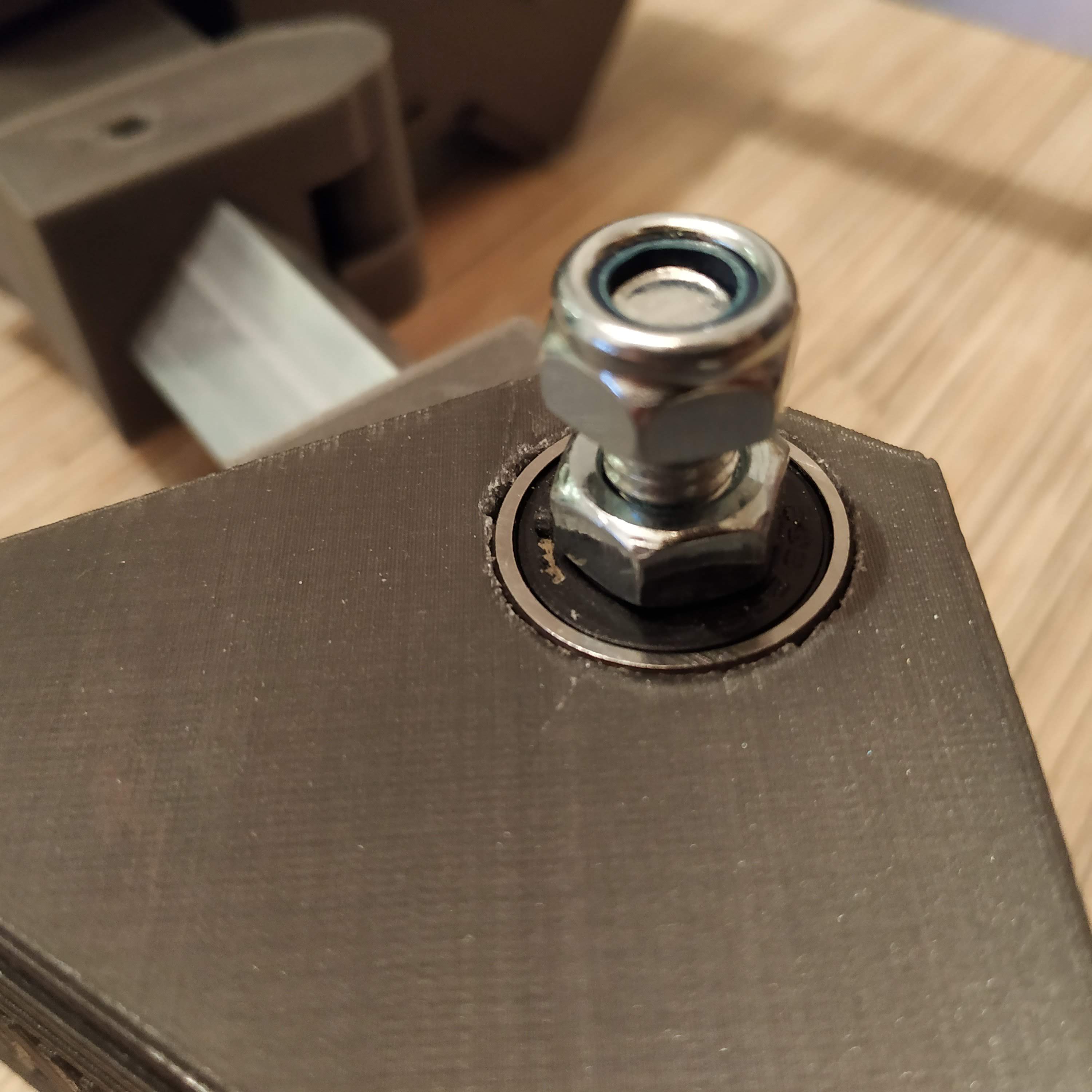
19. Put 2 M8 nyloc nuts onto pedal mount bolts:
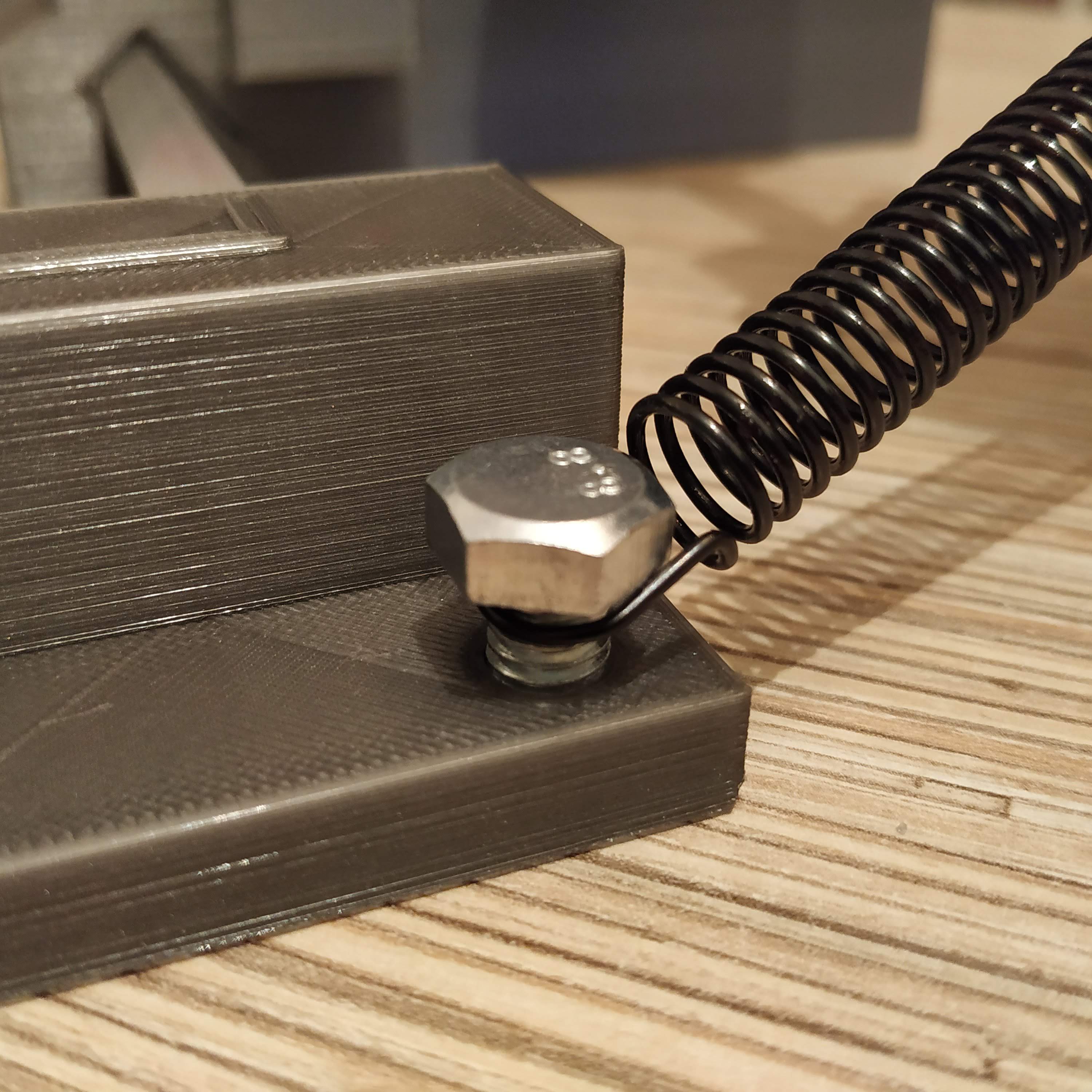
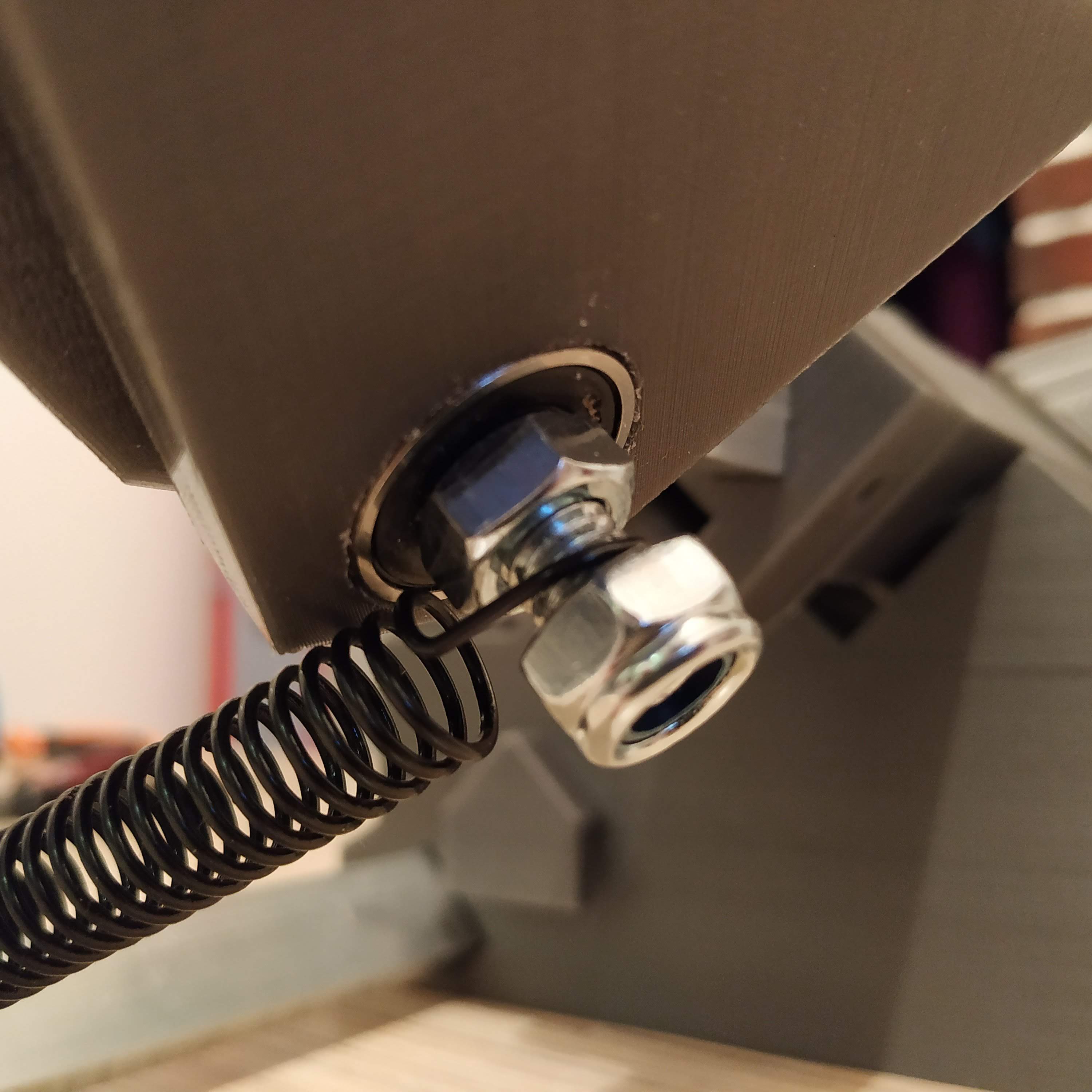
20. Put springs on as shown in pictures below and tighten nyloc nuts a bit until they will be barely touching springs, springs should be able to rotate freely. Pedals should be more or less centered now, if they are slightly off the center, do not worry about it too much, you won’t feel it at all.
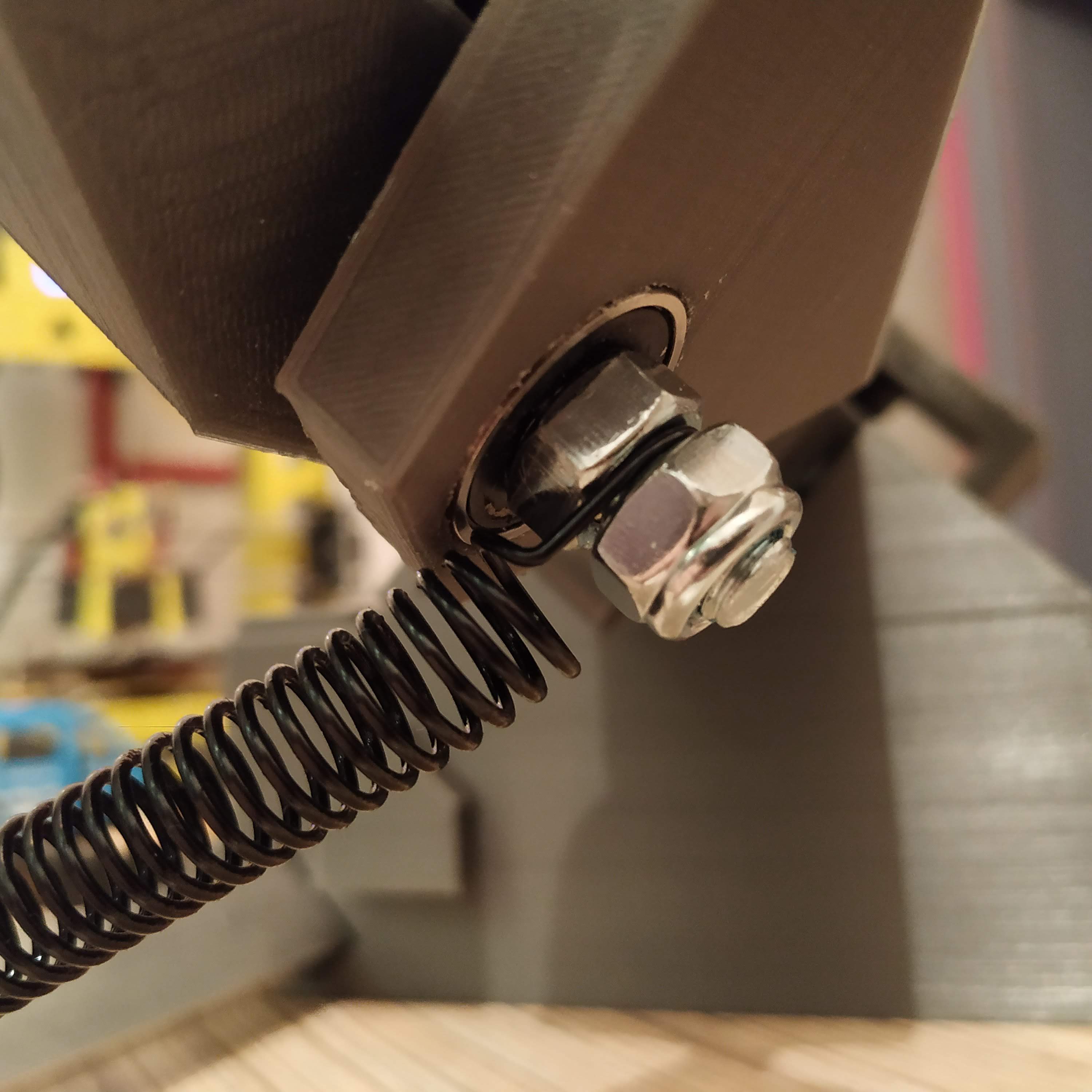
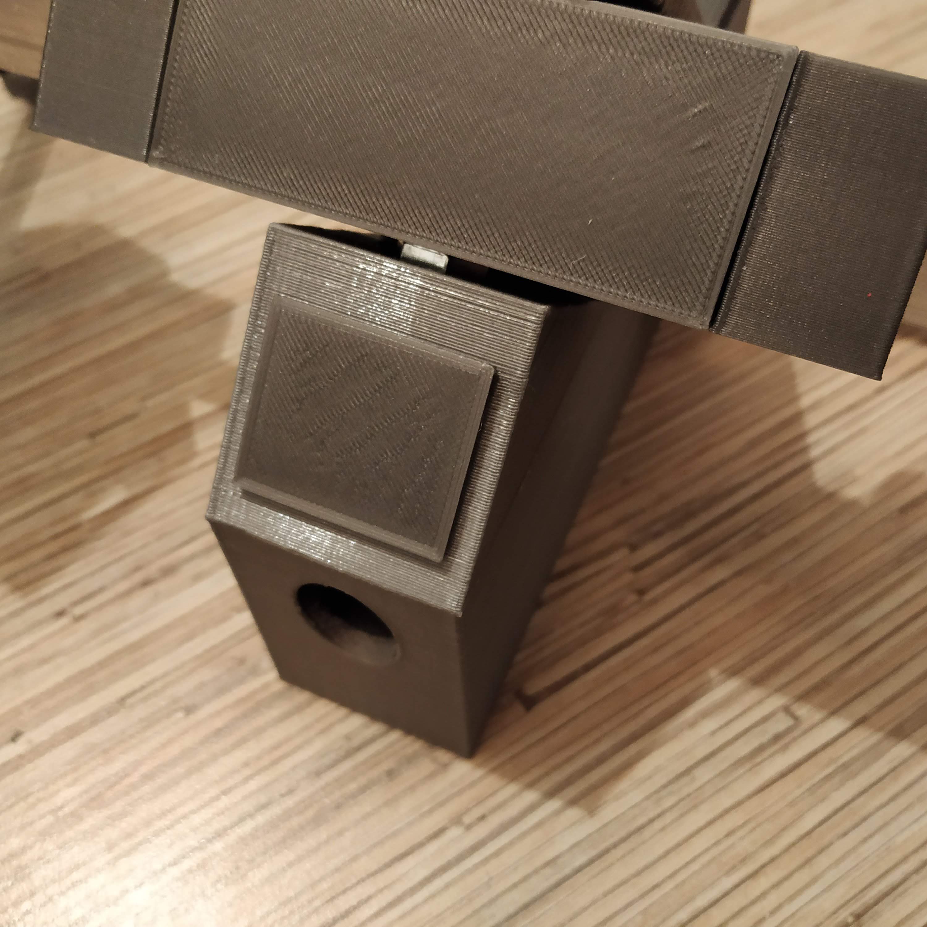
21. Press-fit the front cover into its square socket. We have finished the mechanical part of an assembly process. Let’s move on to electronics!
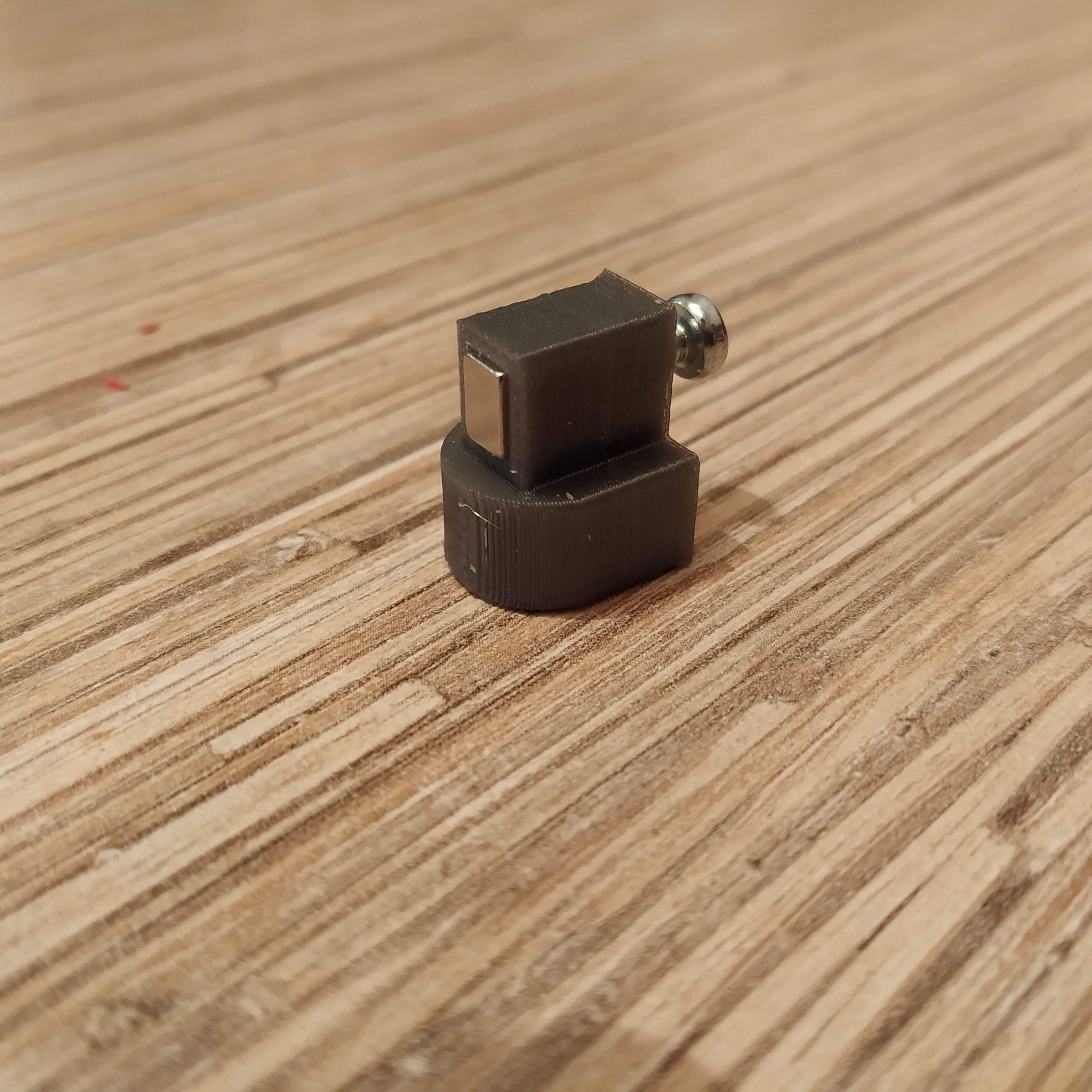
22. Put a magnet into a magnet holder. Insert an M3x6mm screw into the hole in the rear wall of the holder and tighten it until it touches the magnet.
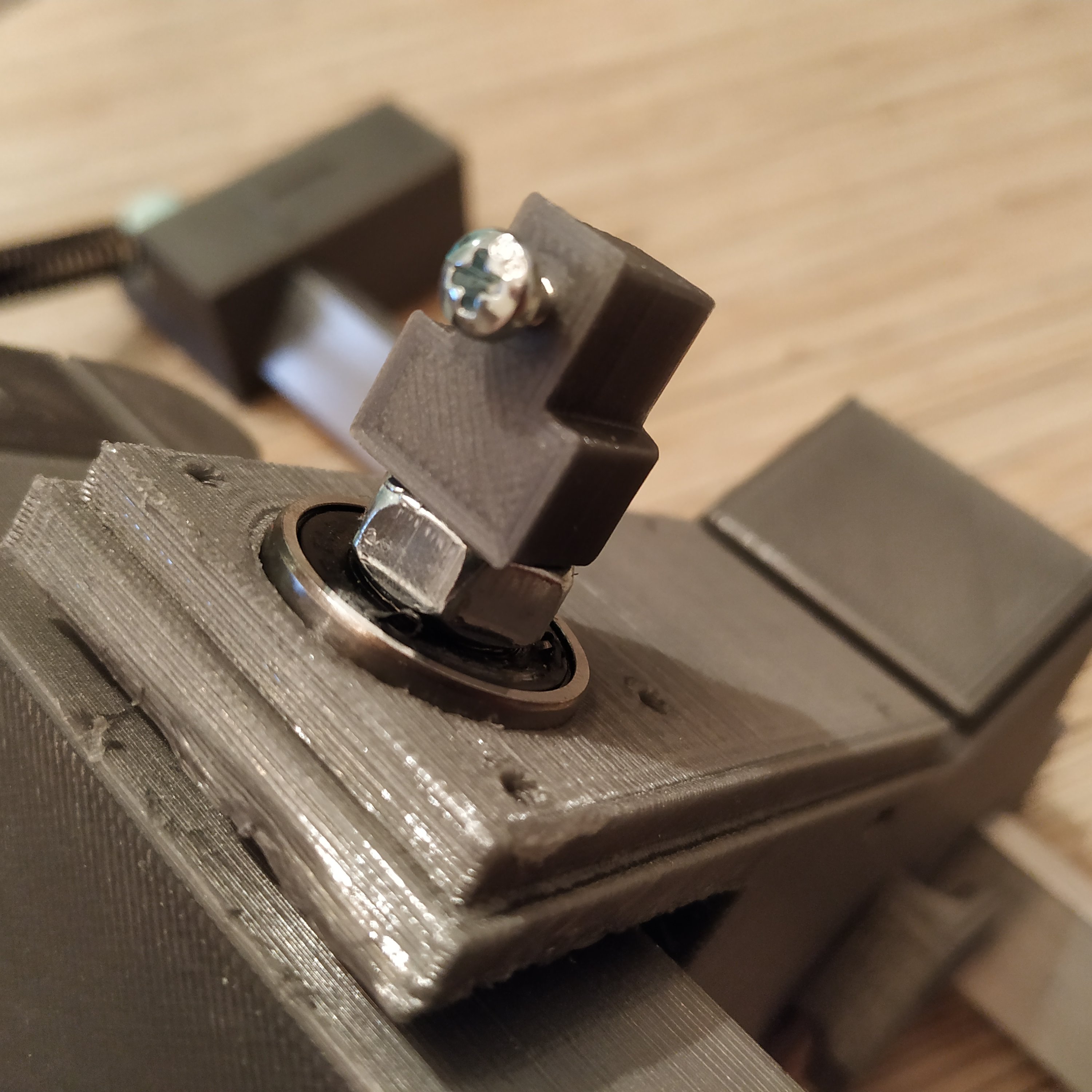
23. Put the magnet holder onto the main axis bolt of pedals.
24. Cut a 3-wire cable off the ribbon and solder it to a SS495A1 sensor.
25. Press-fit the sensor into its socket, add a drop of superglue to fix it in place, and a drop of hot glue to fix legs of the sensor and prevent them from touching each other.
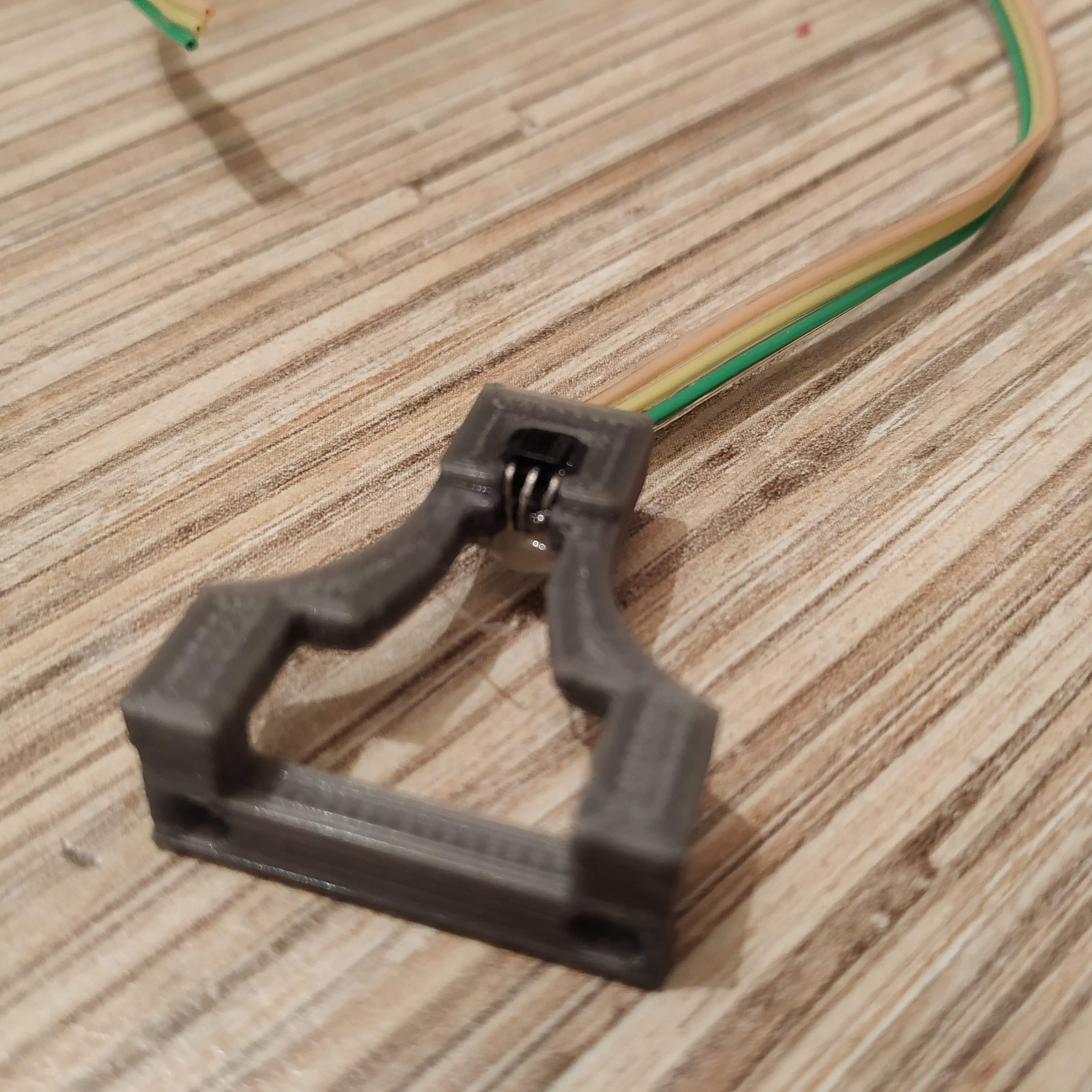
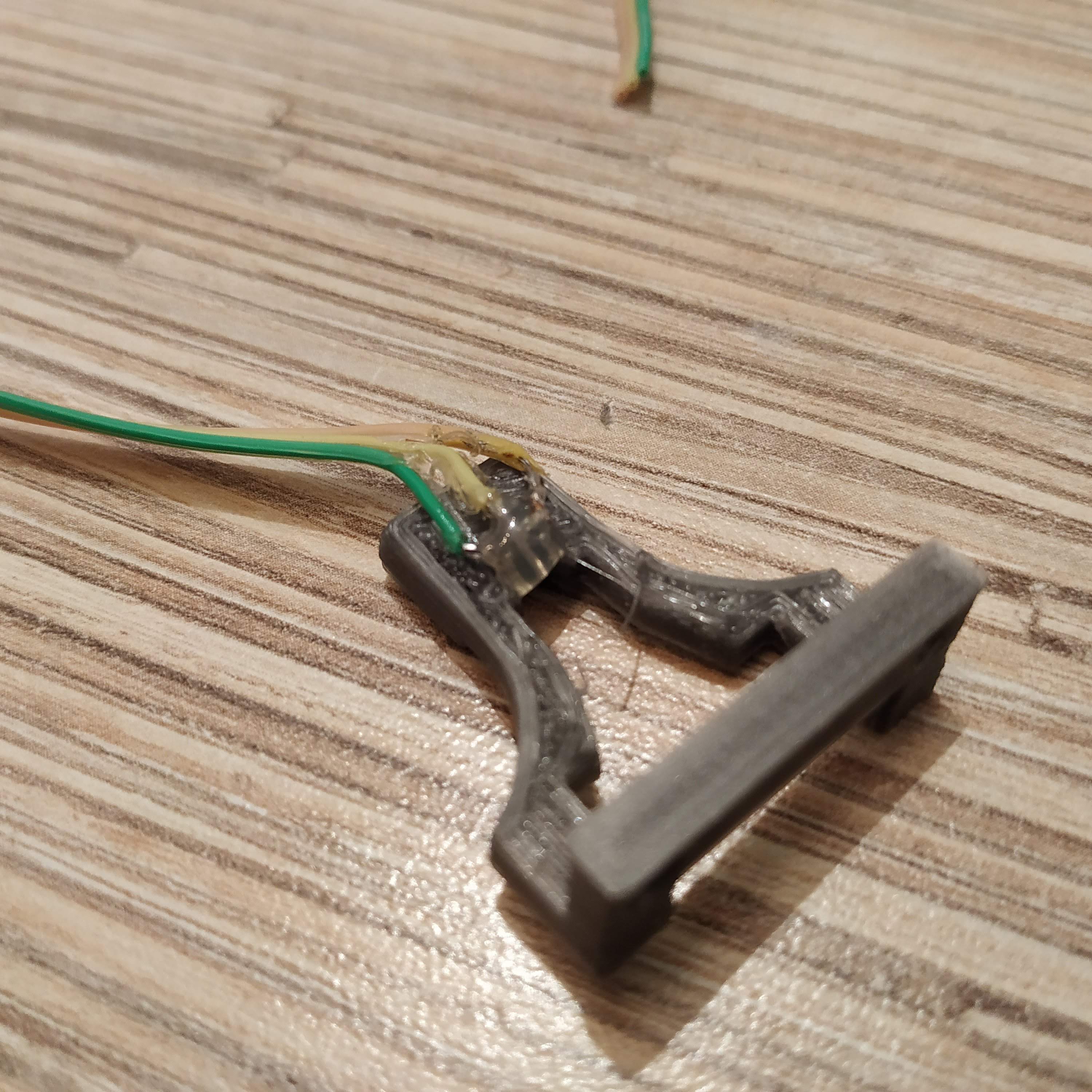
26. Put the sensor holder onto the frame and fix with 2 M3x16mm screws. Fasten the sensor cable to the frame with a drop of hot glue.
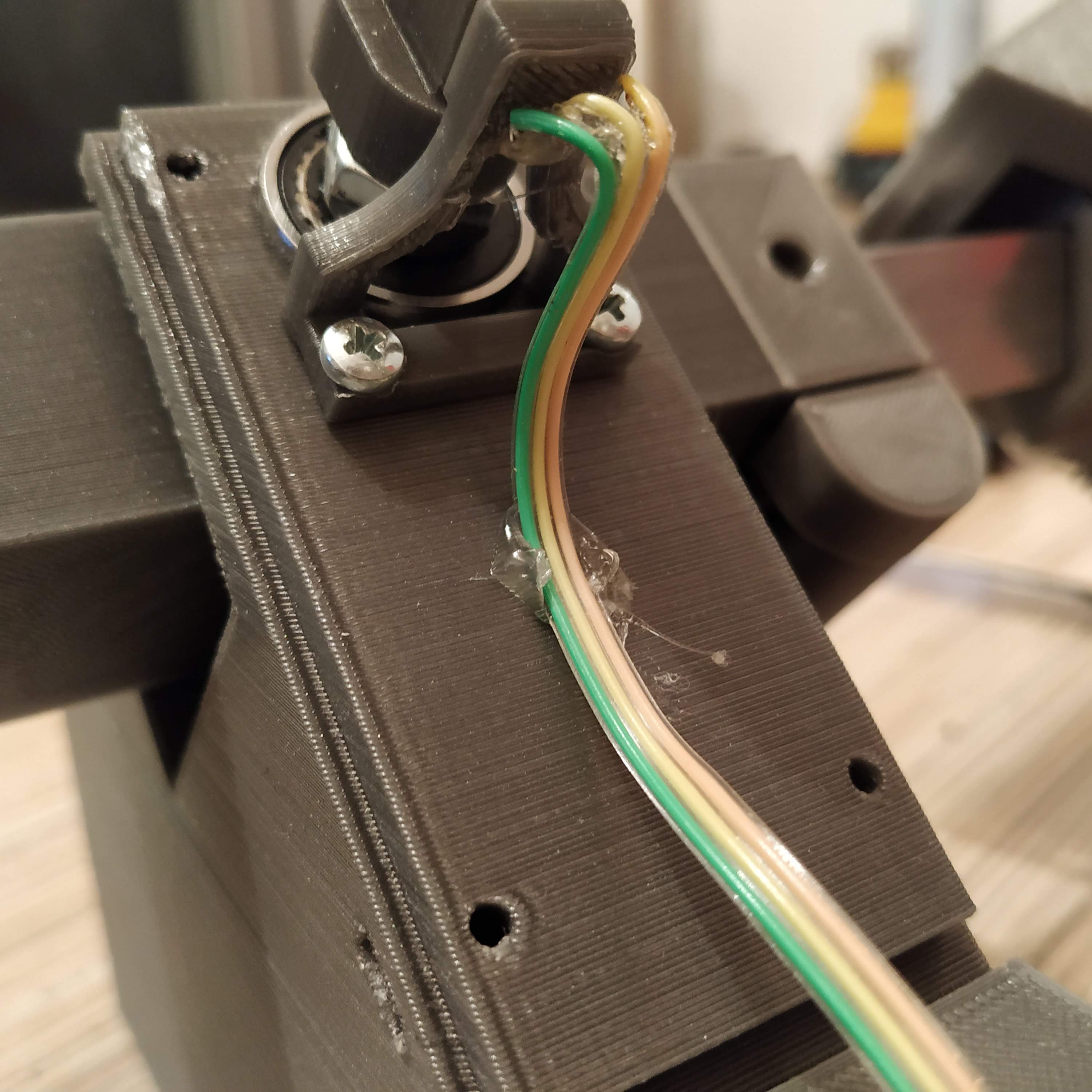
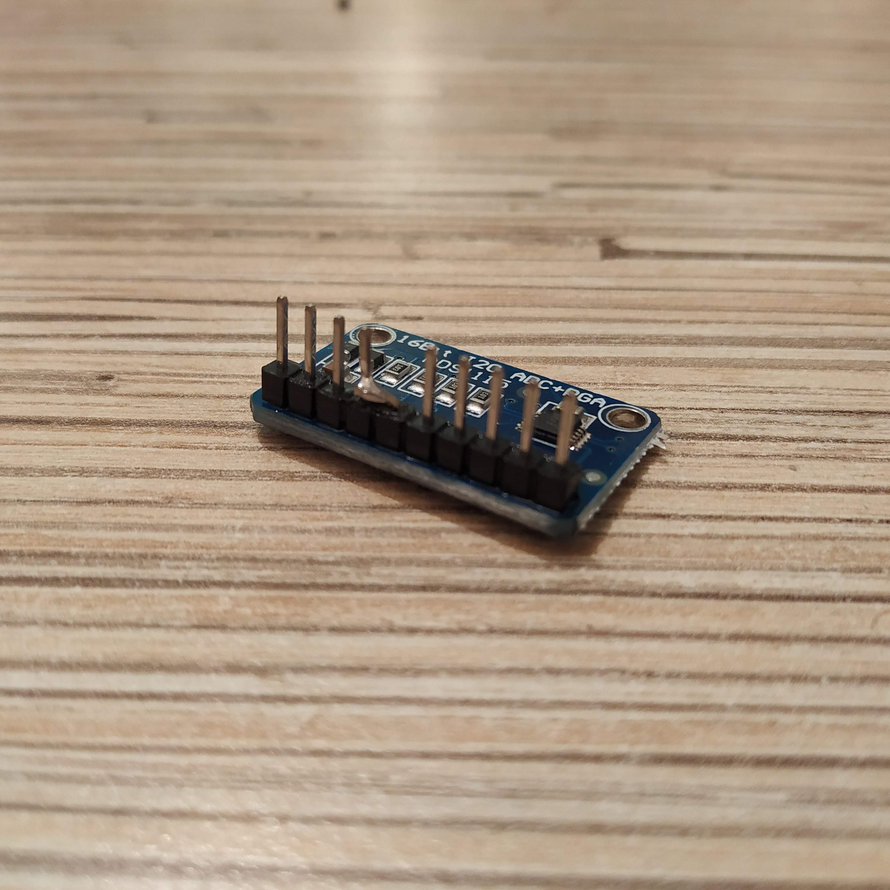
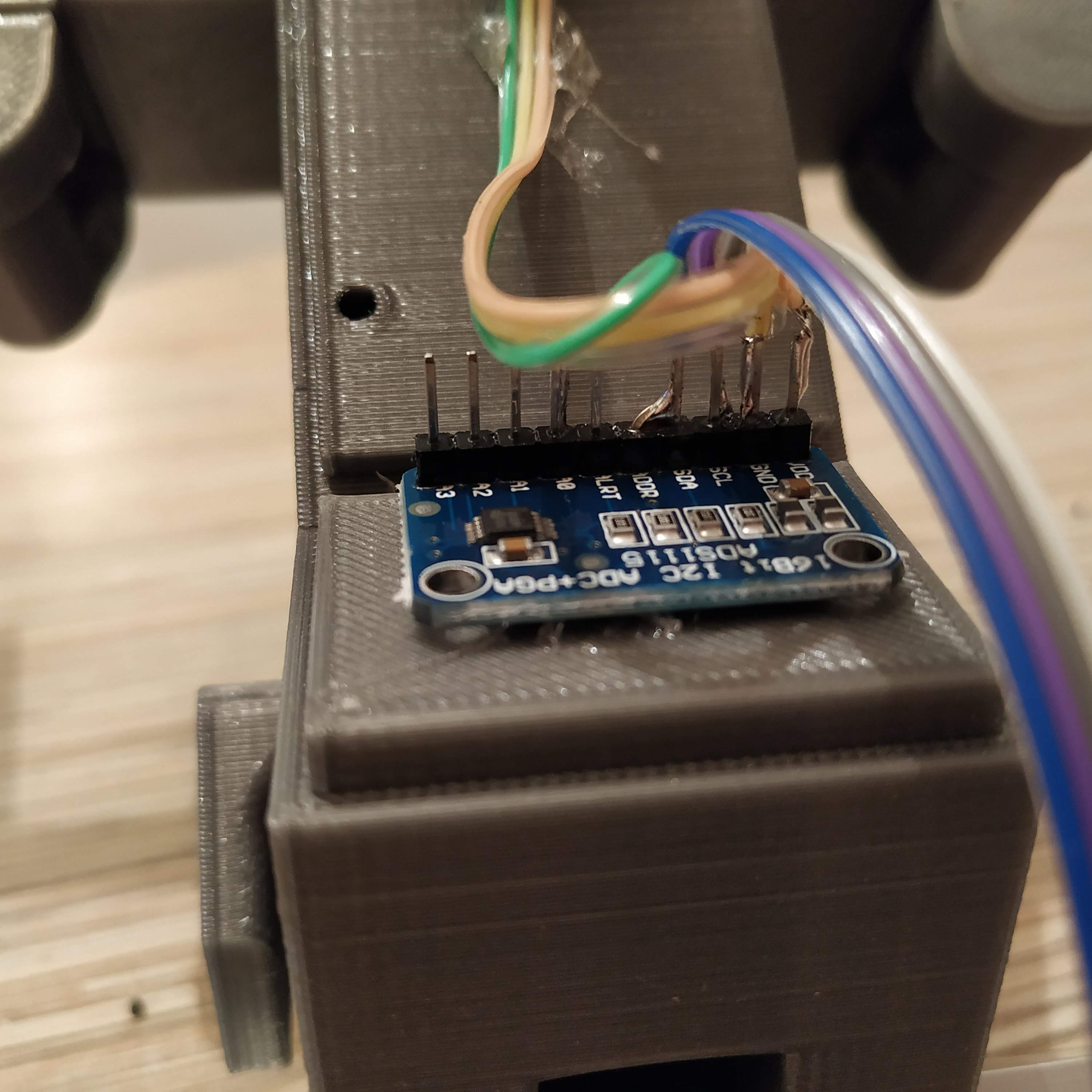
27. Solder the header to an ADS1115 ADC board. Bend the ADDR pin, connect it to the SDA pin, cut an excess length of ADDR pin and solder it to the SDA pin.
28. Solder 4-wire cable cut off the ribbon to 1st 4 pins of an Ethernet socket.
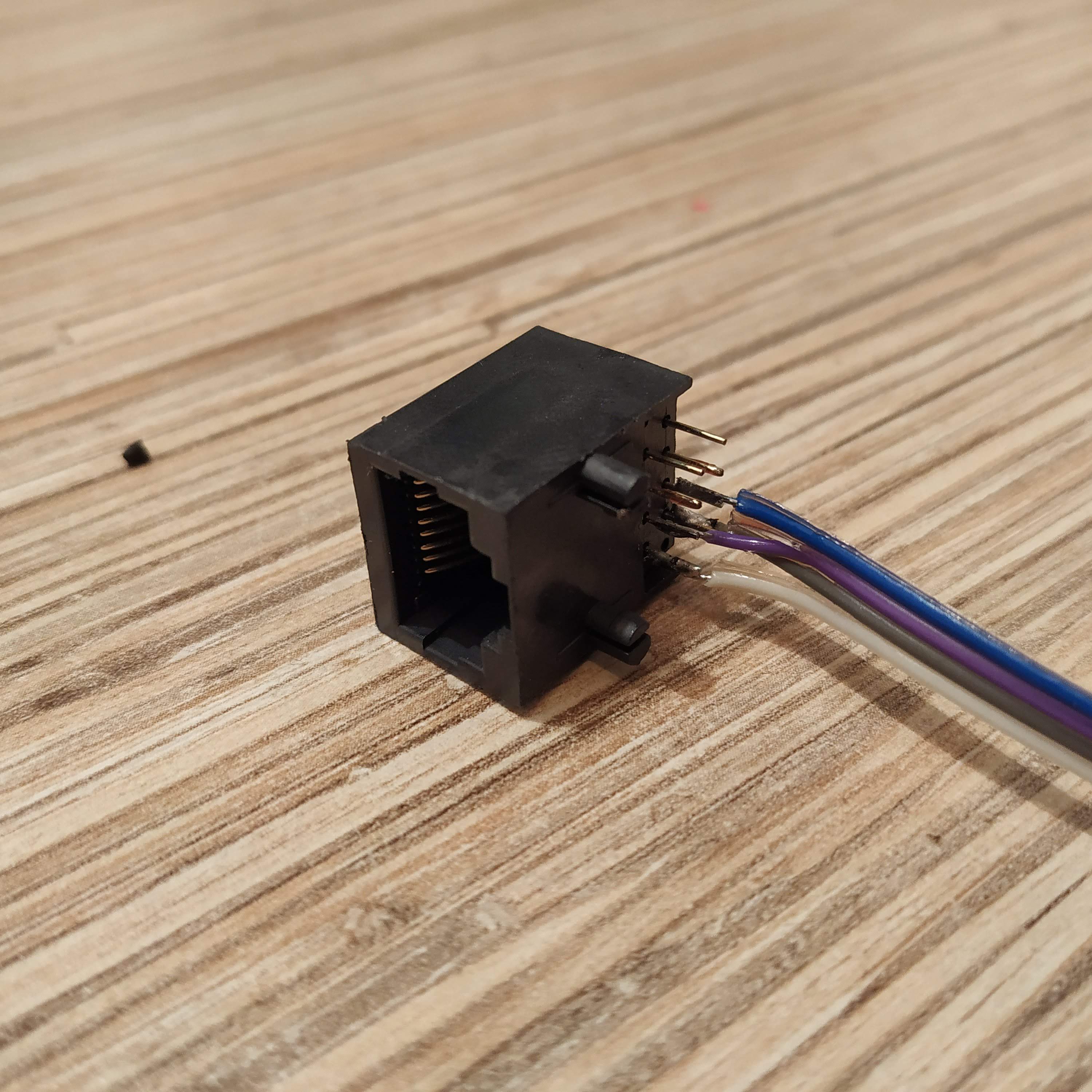
29. Connect everything as follows:
- VCC → SS495A VCC → ethernet socket pin 1 (orange-white wire on the plug)
- GND → SS495A GND → ethernet socket pin 2 (orange wire on the plug)
- ADDR → SDA (bus address 0x4A)
- A0 → SS495A signal
- SCL → ethernet socket pin 3 (green-white wire on the plug)
- SDA → ethernet socket pin 4 (blue wire on the plug)
30. Fix the ADC board to the frame with a drop of hot glue.
31. Calibration time! Connect the pedals to the master controller. They will be assigned to the rudder axis of the 1st Arduino Leonardo in the list. Open the master controller sketch and uncomment the following line under “g_helicopter_pedals” tab:
//Serial.println(rudder); //uncomment to calibrate pedals
32. Flash the controller, open Serial port monitor in Arduino IDE and carefully rotate the magnet holder until you will see the value close enough to 16384. Using the magnet holder adjustment screw, set desired travel of pedals. The further from the sensor is the magnet, the larger turn will be needed to reach axis boundaries. Default setting: adjustment screw barely touches the magnet (maximum travel). When finished, comment out “Serial.print” line again and re-flash the controller. That’s it calibration is now finished!
33. The only thing that’s left now is to press-fit the Ethernet socket to the square slot of the electronics housing part, pour some hot glue to fix it there, install the housing part onto the frame and fix with 4 M3x50mm screws.
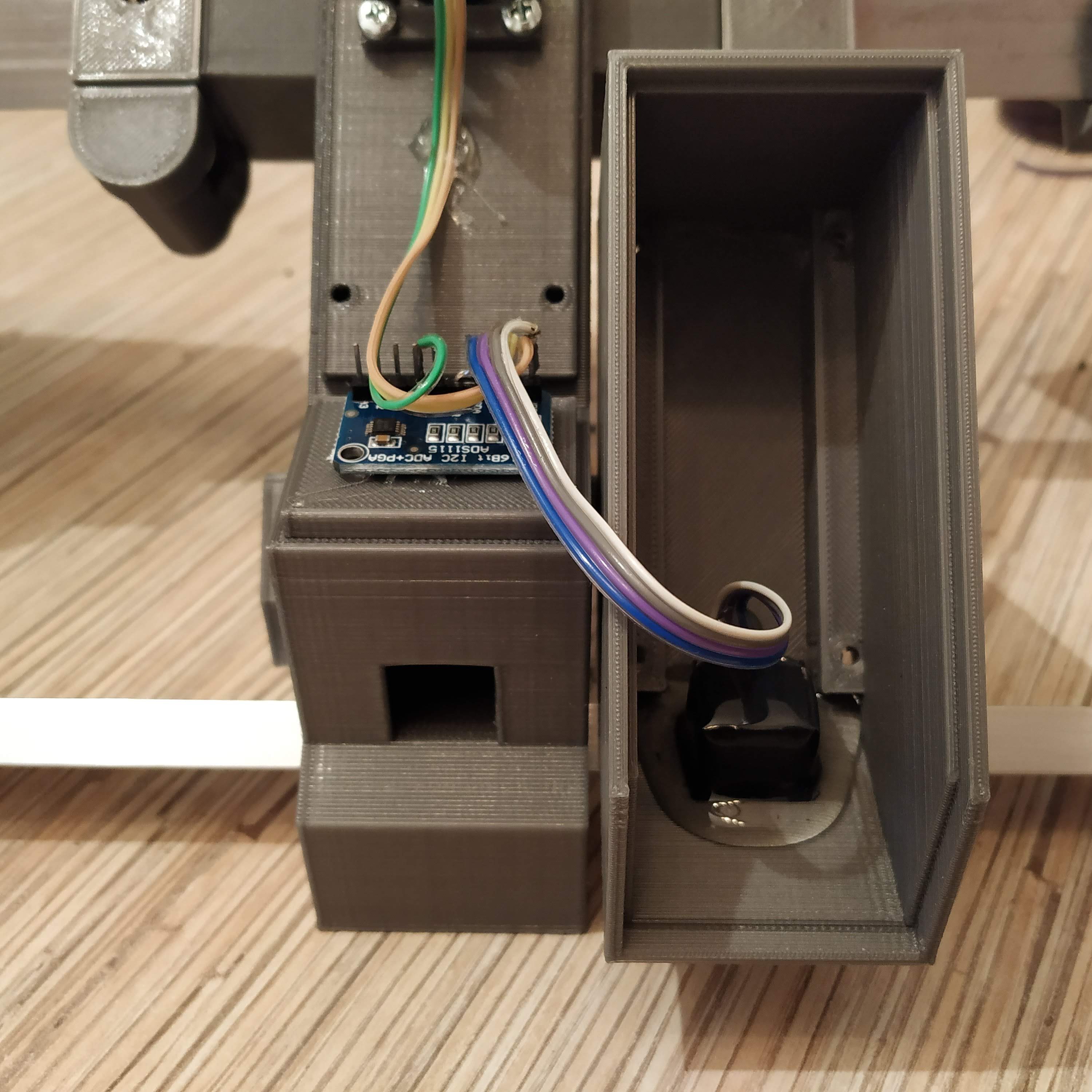
You can now pull an ethernet cable through a square cable channel in the frame, connect it to master controller and fly!
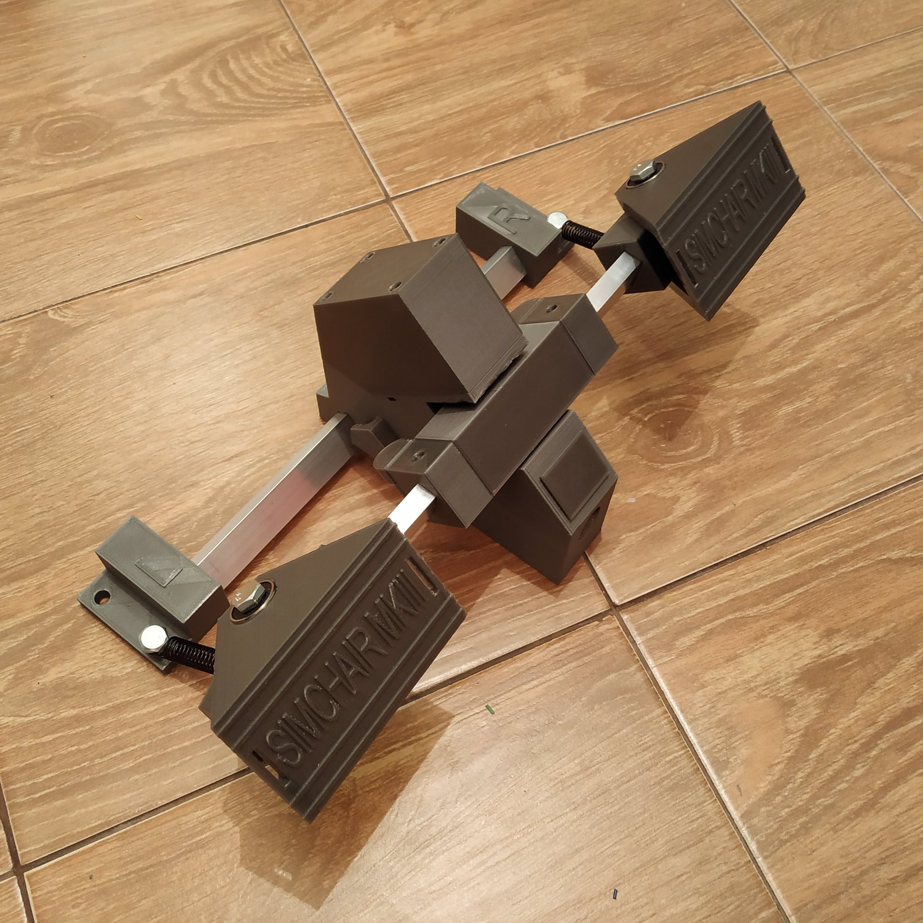
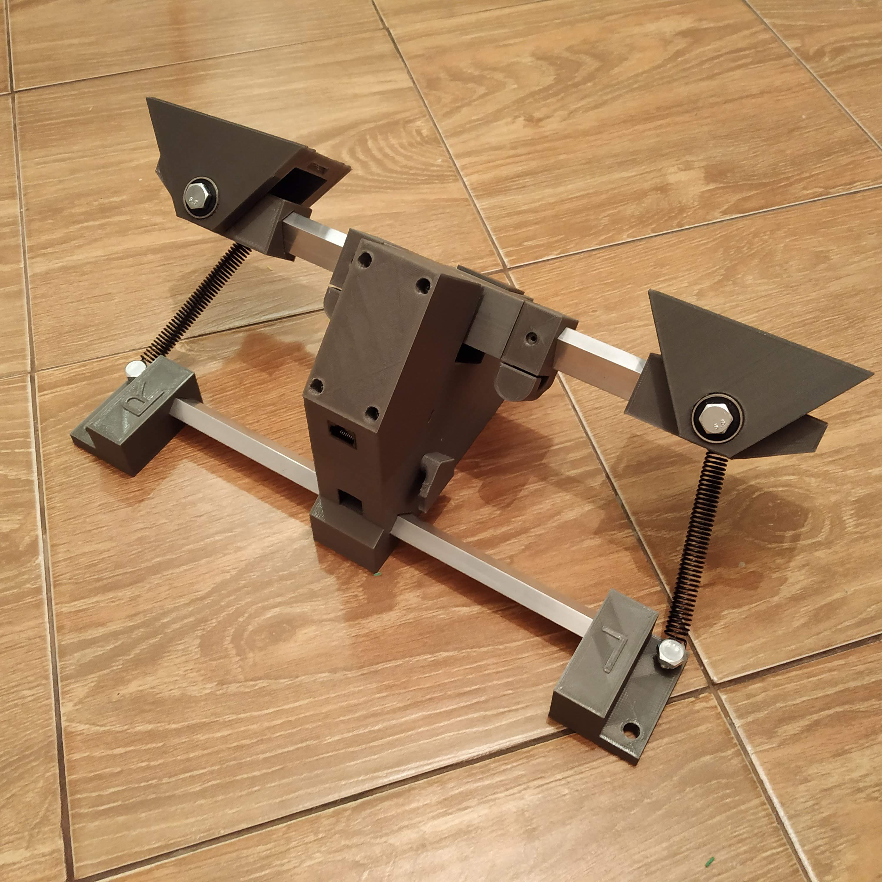
Congratulations! You’ve just built yourself a new set of pedals! :)

