simchair4:guide_collective_base_evo_usb
This is an old revision of the document!
Table of Contents
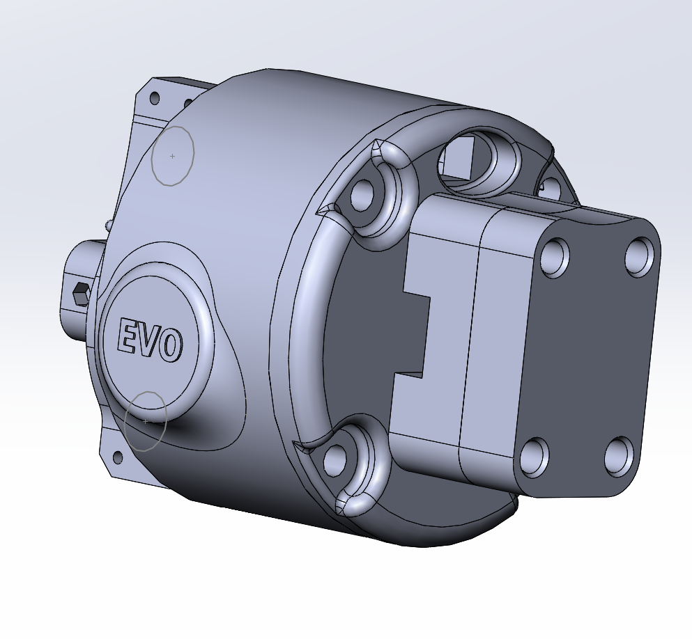
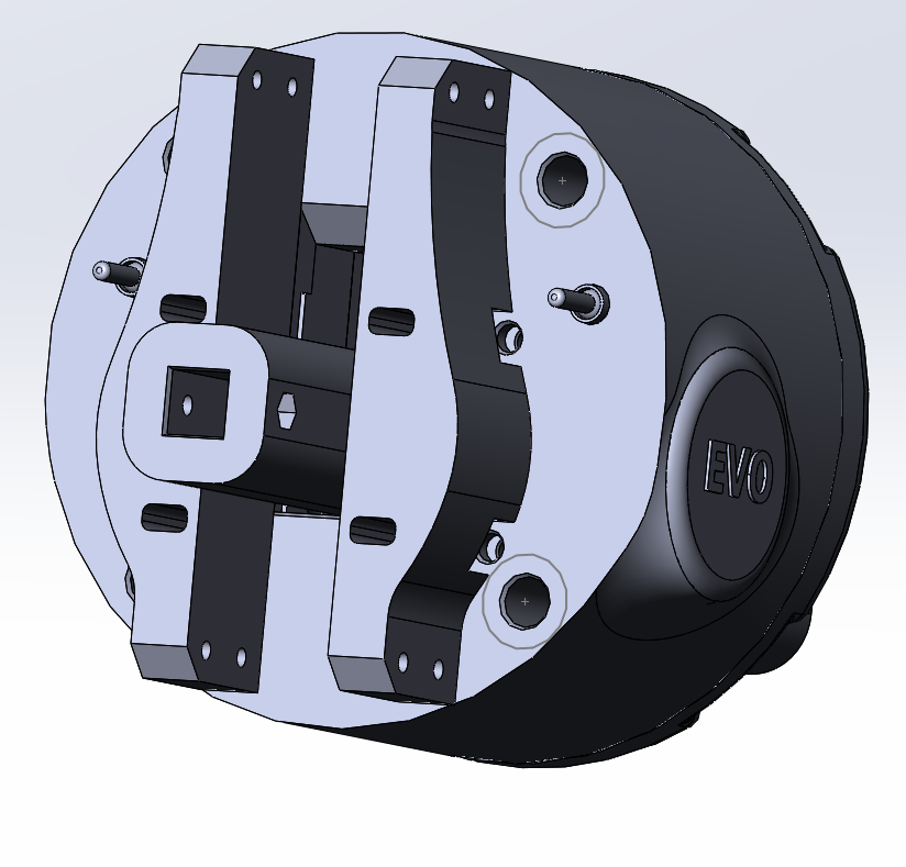
Simchair MKIV EVO USB collective lever base
Components
- 1 x 10x10mm aluminum square pipe (200mm length for single throttle)
- 1 x SS495A1 hall sensor
- 2 x MTS-103 ON-OFF-ON switch
- 1 x 6x6x4mm square magnet (or 5x5x5mm)
- 1 x M6x70mm screw
- 2 x M6 fender washers (sometimes called reinforced washers)
- 1 x M6 nut
- 2 x M6x18x8mm hubs
- 6 x M4x40mm screws
- 6 x M4x70mm screws (2 of them for securing devices that go into the slot on top)
- 1 x M3x20mm screw (round head)
- 1 x M3 nyloc nut
- 4 x M4 nyloc nuts
- 4 x M3x50mm screws for tensioner halves contraction
- 4 x M8x70 bolts
- 4 x M8x75mm bolts
- 8 x M8 nuts
- 10 x M8 washers (regular)
- 4 x M8 spring washers
- 1 x bag of M4 nuts
- 4 x 608 bearings (standard skateboard bearings)
- 1 x Arduino Pro micro
- super glue (cyanoacrylate), hot glue gun
- 1 x USB-B socket USBB-1J (DS1099-W)
Repository path
simchair4_models\printable components\peripherals\helicopter\collective lever\a_base\ac_base_evo_usb - models
Features
If you already have your nice sim pit setup you don't want to change, and just need a solid collective lever to complete it, this is your choice. This version here does not have the top extension slot, if you want it, just take the enclosure part from the regular EVO version, and route the ethernet cable between the base and the extension inside of the base box.
This lever has the following functions:
- global collective mode switch - maps physical switches of head and pedestal that support it to 3 different sets of joystick buttons. For Huey and 412 heads - does the same with hat switches.
- special throttle functions:
- button press on throttle cutoff - when you close the lever completely, the joystick button on the base should light up. For tactile mark detent levers - the IDLE REL button of the collective head should be held while closing the throttle past the detent; for levers with a physical latch - the button should light up when you close the throttle normally. Assign that button to the throttle latch in XPlane.
- DCS HUEY compat mode - will press PgDn and PgUp when closing and opening throttle below the detent to push your throttle while below the detent in DCS Huey where it is not recognized as an axis
- axis switching: this lever can drive 2 throttle axes with 1 physical throttle grip. The right mode switch controls which axis is assigned to the throttle pot at the moment. When you flip the switch, you need to reach the position of your other axis before it will start moving, to avoid sudden axis value bumps and having to remember what is where.
Assembly Guide
Please follow the assembly guide for the classic base up to the point of wiring things. From there. please follow the table below:
| CONN POINT A | CONN POINT B |
|---|---|
| MODE SW LEFT BOTTOM PIN | Pro Micro PIN 4 |
| MODE SW LEFT MIDDLE PIN | Pro Micro GND |
| MODE SW LEFT BOTTOM PIN | Pro Micro PIN 5 |
| MODE SW RIGHT TOP PIN | Pro Micro PIN 6 |
| MODE SW RIGHT MIDDLE PIN | Pro Micro GND |
| MODE SW RIGHT BOTTOM PIN | Pro Micro PIN 7 |
| SS495A1 VCC | VCC CABLE JOINT |
| SS495A1 GND | GND CABLE JOINT |
| SS495A1 SIGNAL | Pro Micro PIN A0 |
| THR POT LEFT (looking from the back) | VCC CABLE JOINT |
| THR POT RIGHT | GND CABLE JOINT |
| THR POT MIDDLE | Pro Micro PIN A1 |
| I2C RIBBON VCC | VCC CABLE JOINT |
| I2C RIBBON GND | GND CABLE JOINT |
| I2C RIBBON SDA | Pro Micro PIN 2 |
| I2C RIBBON SCL | Pro Micro PIN 3 |
| VCC CABLE JOINT | Pro Micro PIN VCC |
| GND CABLE JOINT | Pro Micro PIN GND |
simchair4/guide_collective_base_evo_usb.1615759340.txt.gz · Last modified: 2021/03/14 23:02 by hc625ma
Except where otherwise noted, content on this wiki is licensed under the following license: GNU Free Documentation License 1.3
