This is an old revision of the document!
Table of Contents
Simchair MKIV collective twin throttle lever body with tactile mark detents
This manual describes the process of building a twin throttle lever body, with interchangeable heads, and a physical idle-stop detent latch. This manual was ported from the MKIII version, so you will see the MKIII collective base in the pictures: please ignore this.
Components
- 1 x 200x10x10mm aluminum square pipe
- 1 x 105x10x10mm aluminum square pipe
- 6 x M3x30mm screws and nuts
- 1 x M3 x 35mm screw and a nut
- 1 x M4x80 bolts
- 1 x PBS-16B button
Repository path
simchair4_models\printable components\peripherals\helicopter\collective lever\b_lever bodies\single throttle
Assembly highlights
none
Assembly Guide
1. Assemble the collective base MKIV using a 200mm piece of 10x10mm aluminum piping.

2. Install the decorative cover onto the 10mm tubing.

3. Press-fit an M4 nut into the socket in the throttle 1 frame part 1.

4. Insert a potentiometer into throttle 1 frame p1.
5. Put the throttle frame part 1 onto the 10mm tubing. Drill holes in the 10mm tubing, through the holes of the frame part 1.
6. Press-fit nuts into their sockets, insert 2 M3x30mm screws.

7. Route 4-wire I2C cable and a 3-wire pot cable through the lever. This step may require some patience depending on the wires being used.


8. Solder the pot wires, and route the I2C cables through the cable channel, in the throttle 1 frame part 1.

9. Turn the pot fully to the left, then just a notch to the right. Put the throttle grip on (if required, make the hole a bit wider, or squeeze the pot knob a bit, with pliers) in a way, that it will be in “Fully Open” position (See the picture below). Please make sure that the pot is able to rotate freely.

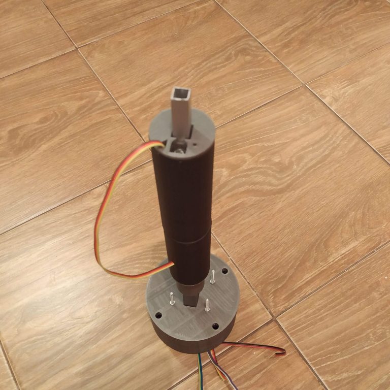
10. Insert a piece of aluminum pipe into throttle 1 p2; drill holes and insert screws.
11.Route wires through cable channel and press-fit throttle1 p2 onto throttle 1 p1
http://hc625ma.org/wp-content/uploads/2018/12/IMG_20181201_014427-e1543675212169-768x768.jpg
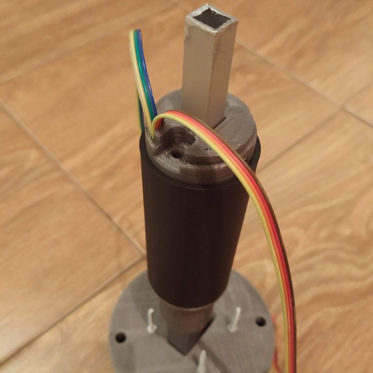
12. Tighten throttle 1 frame parts together with m4x80mm screw, choose a straight one
http://hc625ma.org/wp-content/uploads/2018/12/IMG_20181201_014732-e1543675283954-768x768.jpg
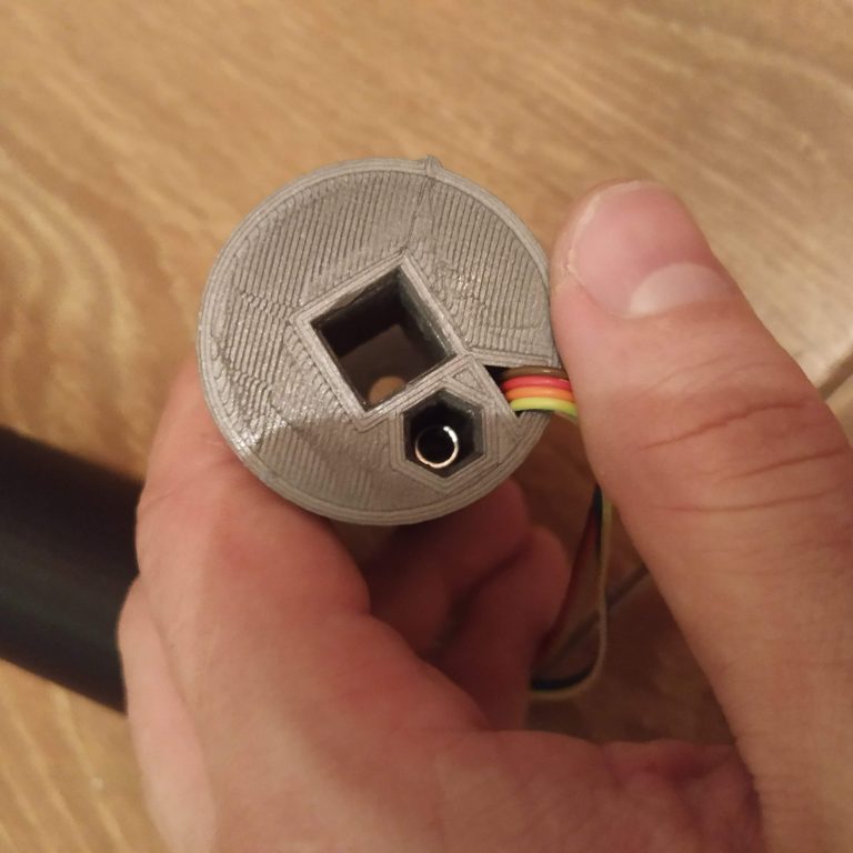
13. Press-fit m4 nyloc nut to throttle 2 p1
http://hc625ma.org/wp-content/uploads/2018/12/IMG_20181201_021649-768x768.jpg
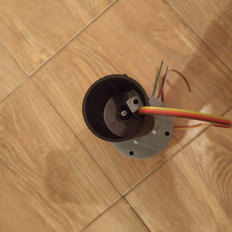
14. Route cables through and attach throttle 2 p1
http://hc625ma.org/wp-content/uploads/2018/12/IMG_20181201_023020-e1543675435815-768x768.jpg
15. Drill holes, insert screws into throttle 2 p1
16. Pull throttle 2 pot wire out of the cable channel and solder it to the throttle 2 pot
17. Attach throttle 2 grip
http://hc625ma.org/wp-content/uploads/2018/12/IMG_20181201_025841-768x768.jpg
18. Insert the aluminum pipe into throttle 2 p2; drill holes and insert screws
19. Pull I2C ribbon cable through throttle 2 p2 and attach throttle 2 p2
20. Fix throttle 2 halves together with an M4x80mm screw
http://hc625ma.org/wp-content/uploads/2018/12/IMG_20181201_033337-e1543675668986-768x768.jpg
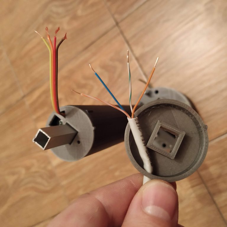
21. Pull a piece of ethernet cable through the I2C connector part, cut and solder I2C ribbon cable wires to it
http://hc625ma.org/wp-content/uploads/2018/12/IMG_20181202_183639-768x768.jpg
