Table of Contents
Bell 206 scale collective head
Summary
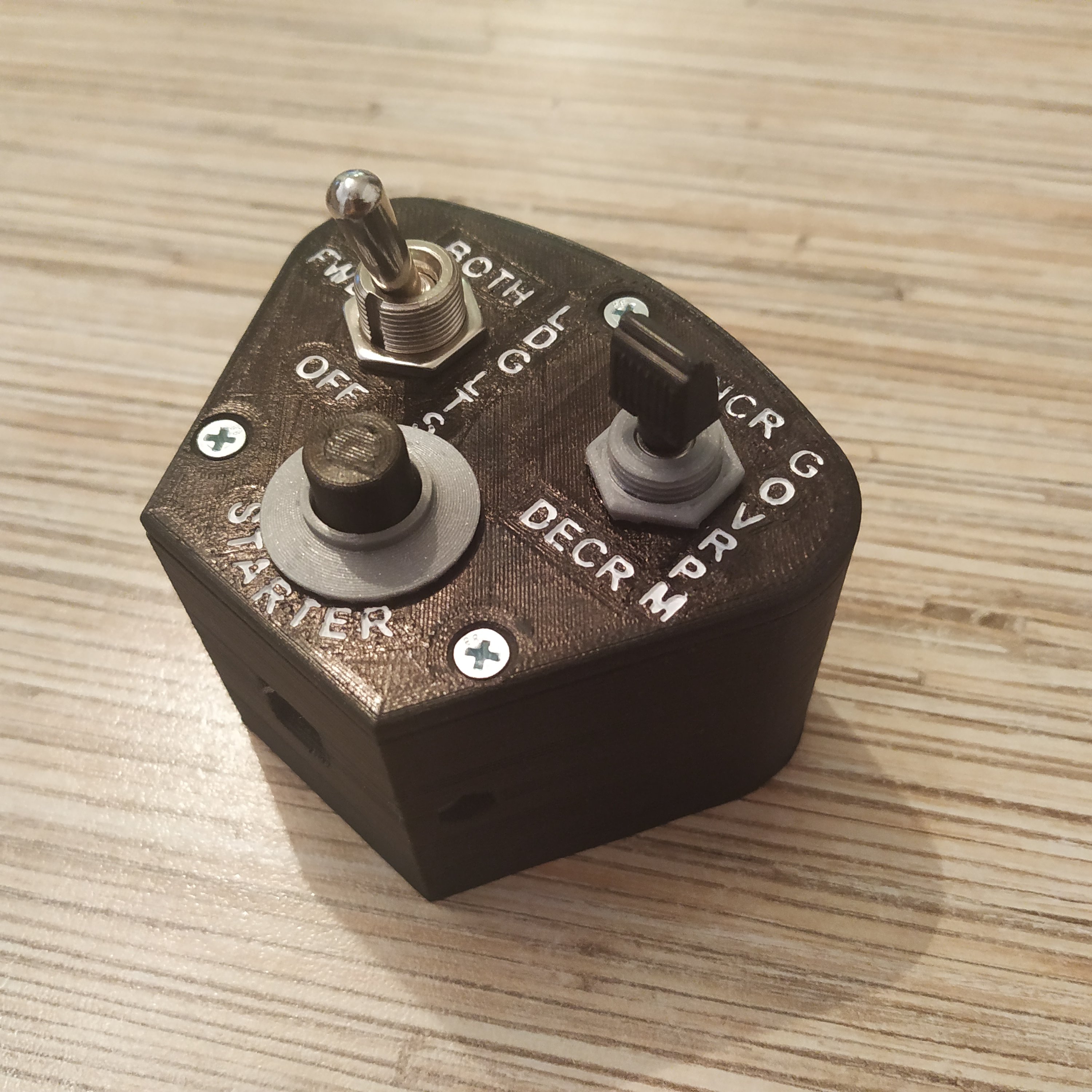
This is a scale Bell 206 collective head! It's made using photos with measurements, so it should be really close to the real one. It's quite simple, but really has everything you need to fly helicopters (if used with the lever body with a physical throttle latch). This head supports the mode switch function for the starter button and GOV RPM switch.
Components
- 1 x MTS-103 - E1 switch
- 1 x KN3(B) SPDT on-off-on switch (12mm)
- 1 x PBS-10B2 button
- 3 x M3x40mm countersunk screws and nuts
- 1 x M3x35mm round head screw and nut
- 1 x Arduino Pro Mini
- 1 x TJ8P8C Ethernet sockets (12,5x15x17,6mm)
Repository path
simchair4_models\printable components\peripherals\helicopter\collective lever\c_switch panels\b206 collective head
Notes
- print small parts at the highest quality setting and 0,1mm layer height
- if you want the version of the panel with letters - print it at 0,1mm as well, adjust the number of layers on top to 5 or 6; use layer width equal the width of your nozzle!
- use a correction white marker to fill letters with white paint, and then carefully paint them over with a black permanent marker (it won't be filling letters!), then paint the rest of the panel with it for colors to match.
Assembly guide
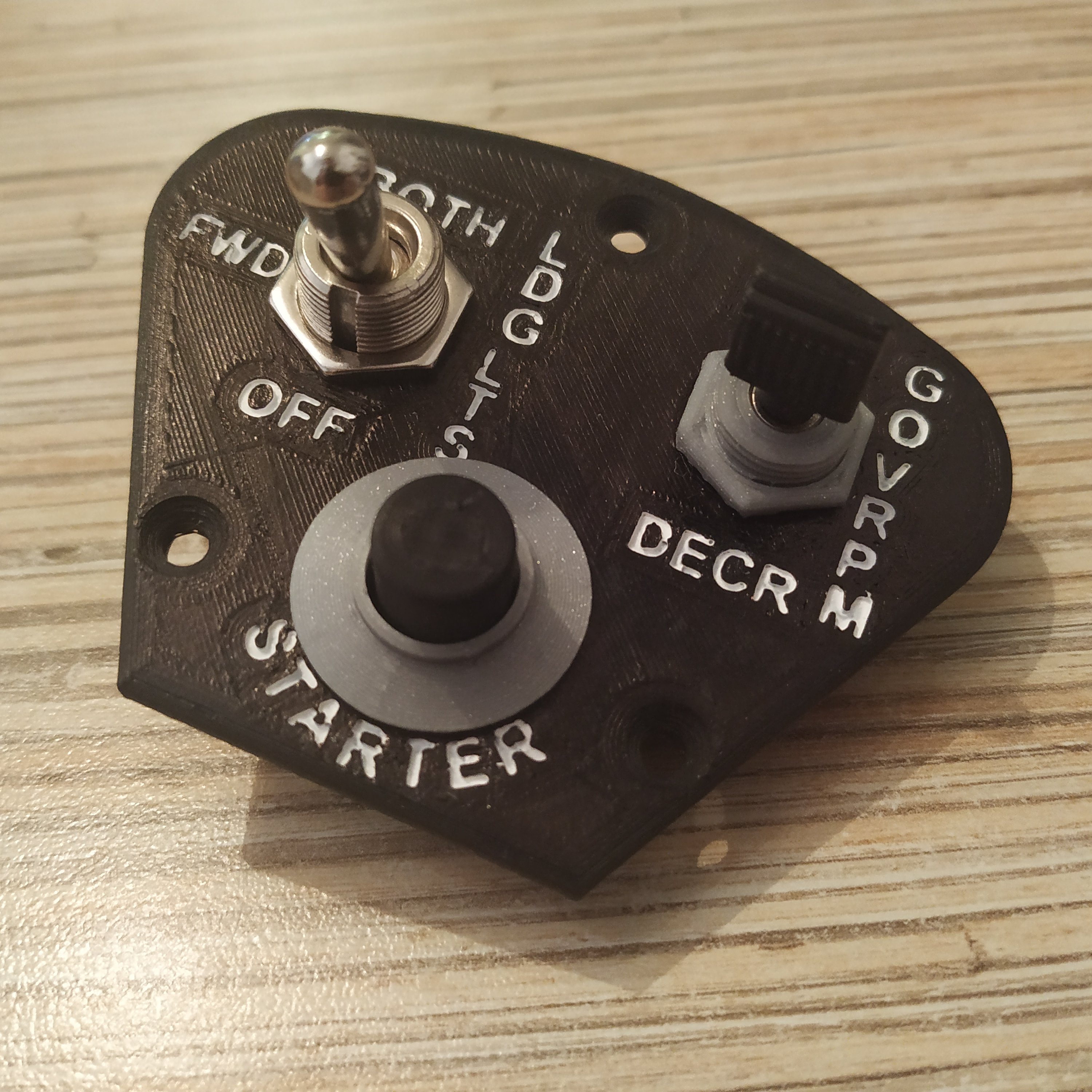
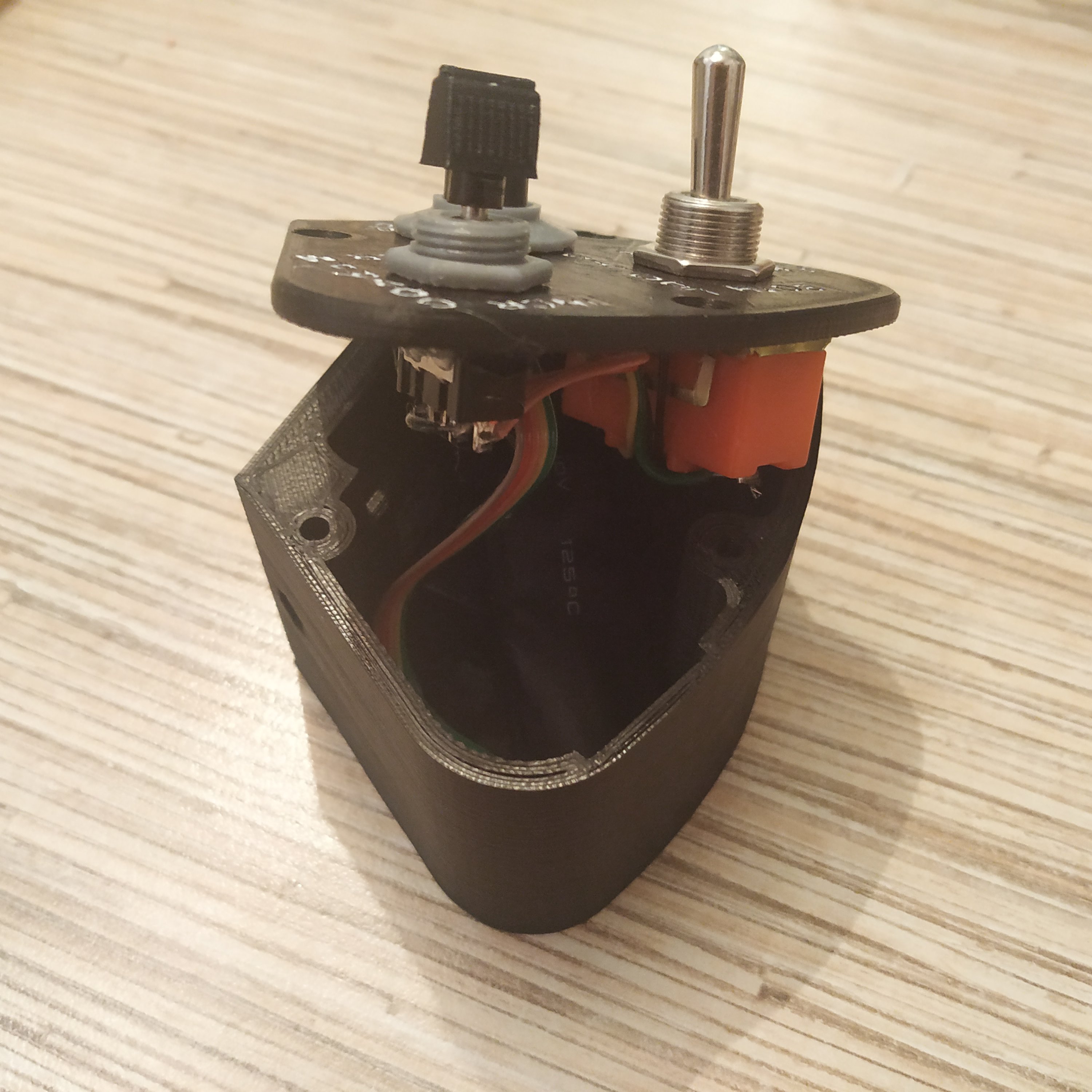
1. Prepare the top panel of choice and insert switches in it. Cut the top off the MTS-123-E1 plastic cap so the scale cap will fit onto it. You can use a black marker to paint the cap if it's not black. Insert the PBS button into its socket, glue the decorative cover on top of it and then put the scale cap on.
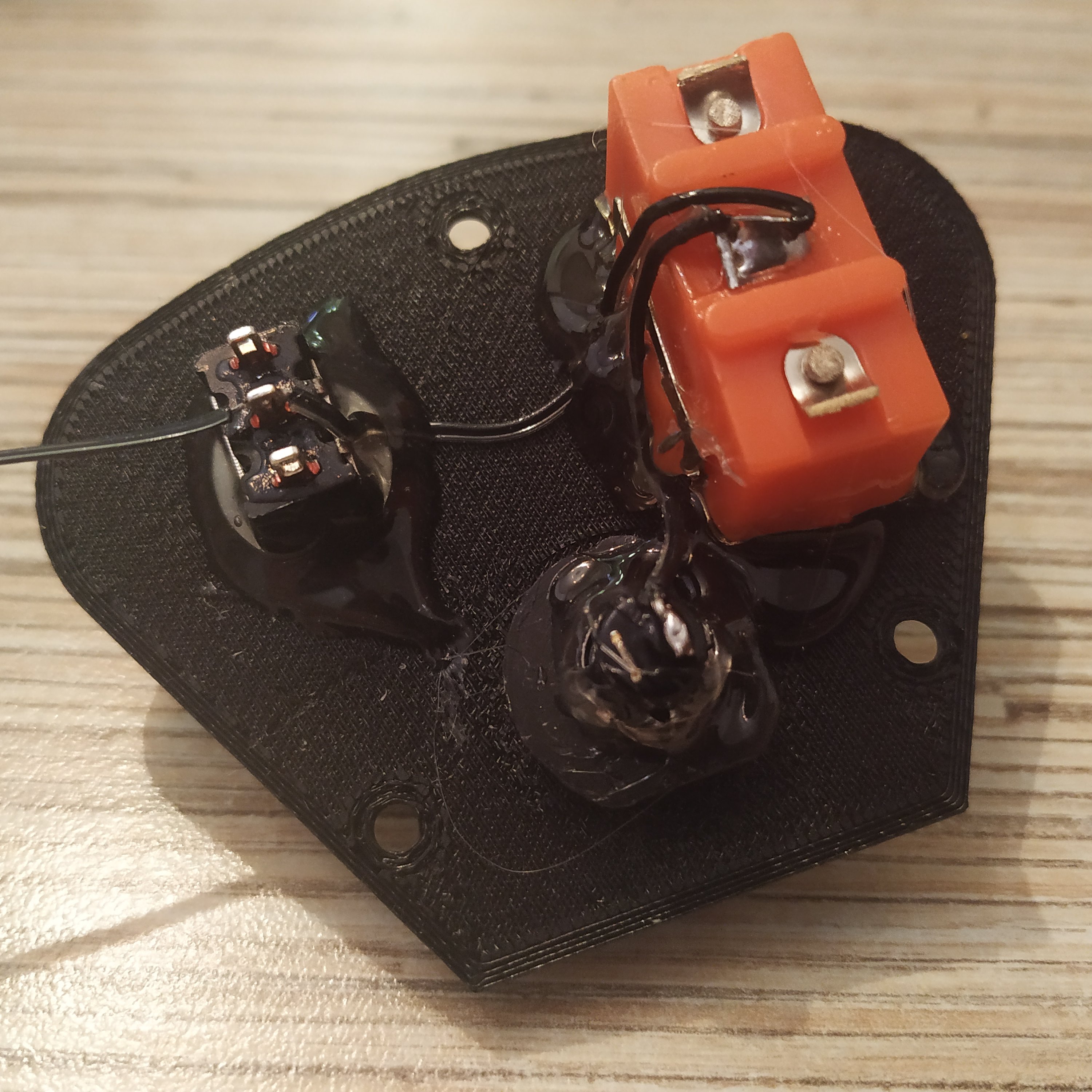
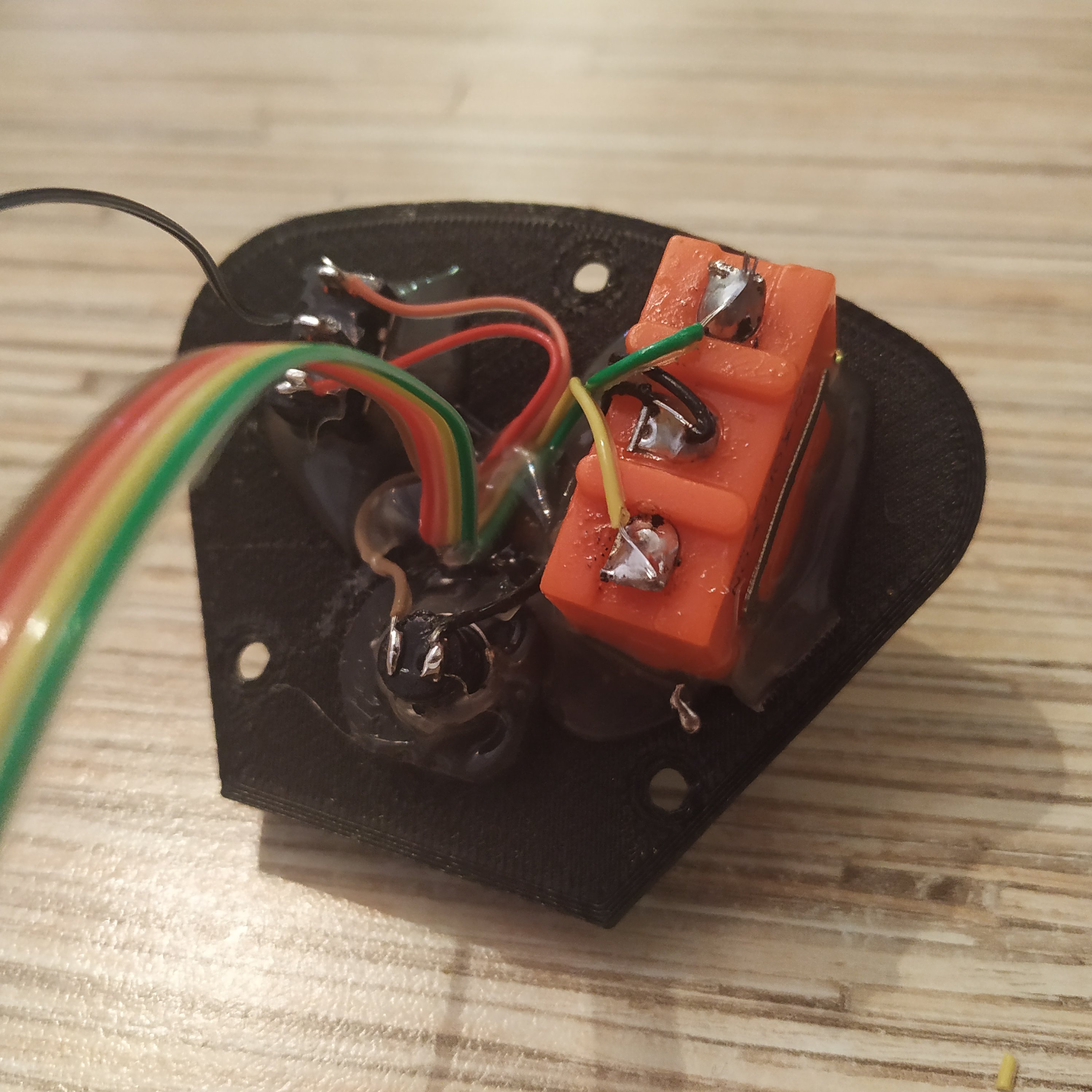
2. Solder the GND wire to switches.
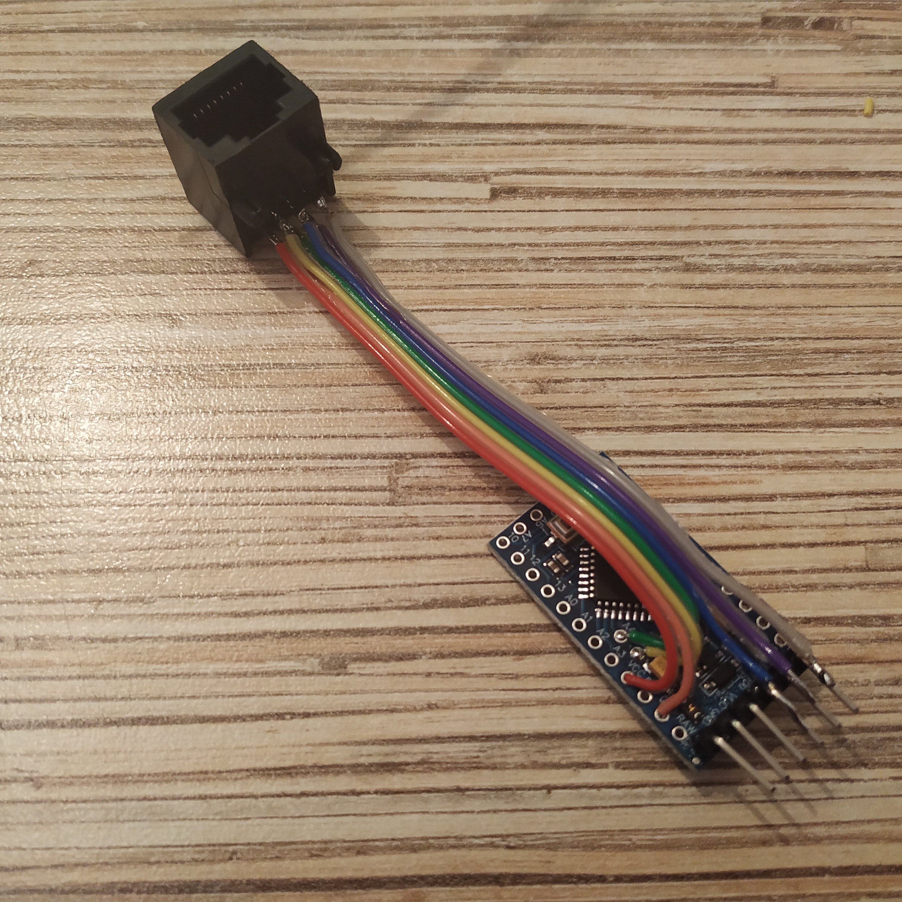
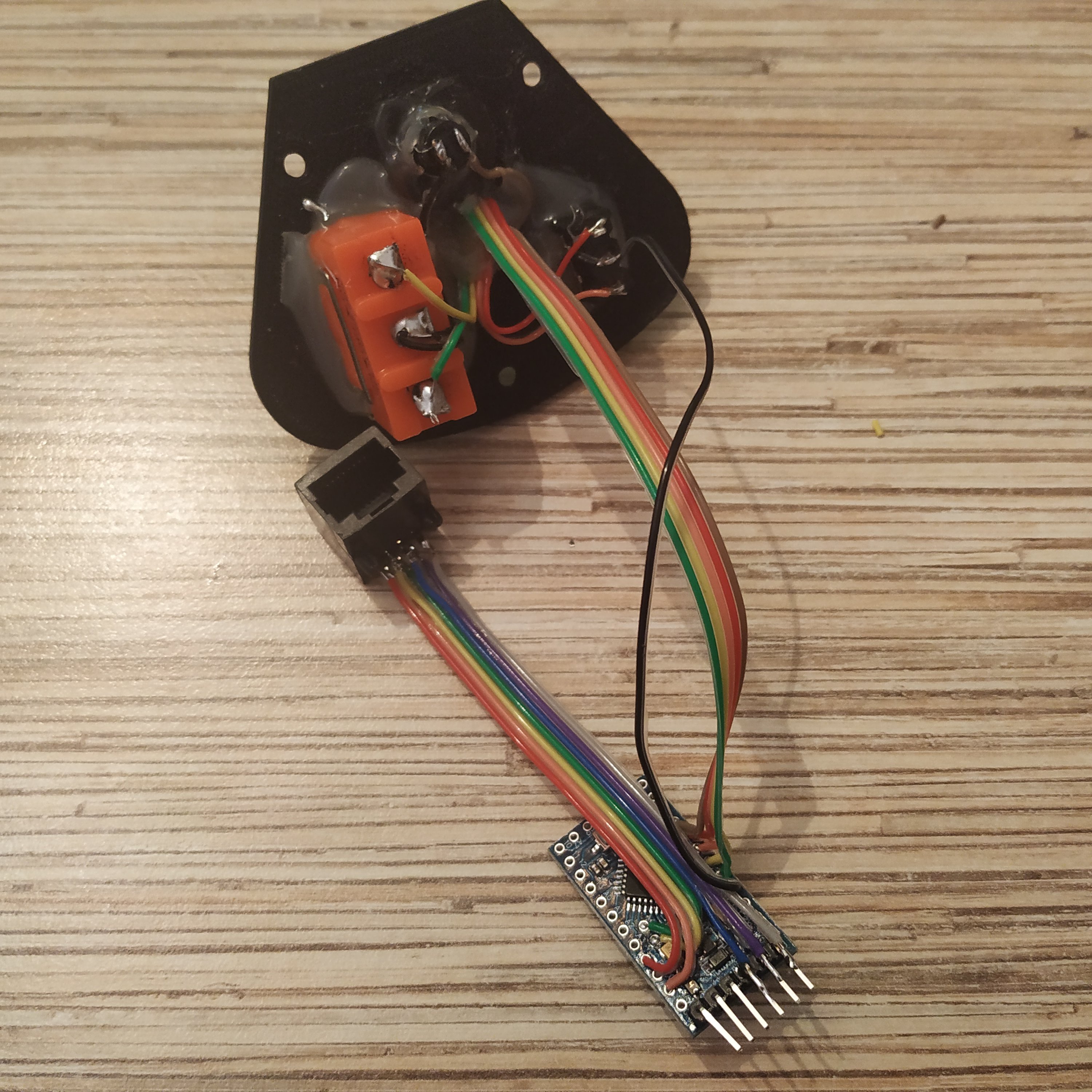
3. Solder an ISP header to Arduino Pro Mini board. Solder a 7-wire cable to an Ethernet socket. Connect it to Pro Mini board as follows:
  ETH SOCKET PIN 1 => VCC
  ETH SOCKET PIN 2 => GND
  ETH SOCKET PIN 3 => SCL (A5)
  ETH SOCKET PIN 4 => SDA (A4)
  ETH SOCKET PIN 5 => Rx
  ETH SOCKET PIN 6 => Tx
  ETH SOCKET PIN 7 => DTR
4. Solder a 5-wire cable to switches as follows (numbers on the pic correspond to Arduino pin numbers):

  LDG LTS SW BOTH SIDE (2) -> PRO MINI PIN2
  LDG LTS SW OFF SIDE (3)  -> PRO MINI PIN3
  GOV RPM INCR SIDE (4)    -> PRO MINI PIN4
  GOV RPM DECR SIDE (5)    -> PRO MINI PIN5
  STARTER BTN (6)          -> PRO MINI PIN6
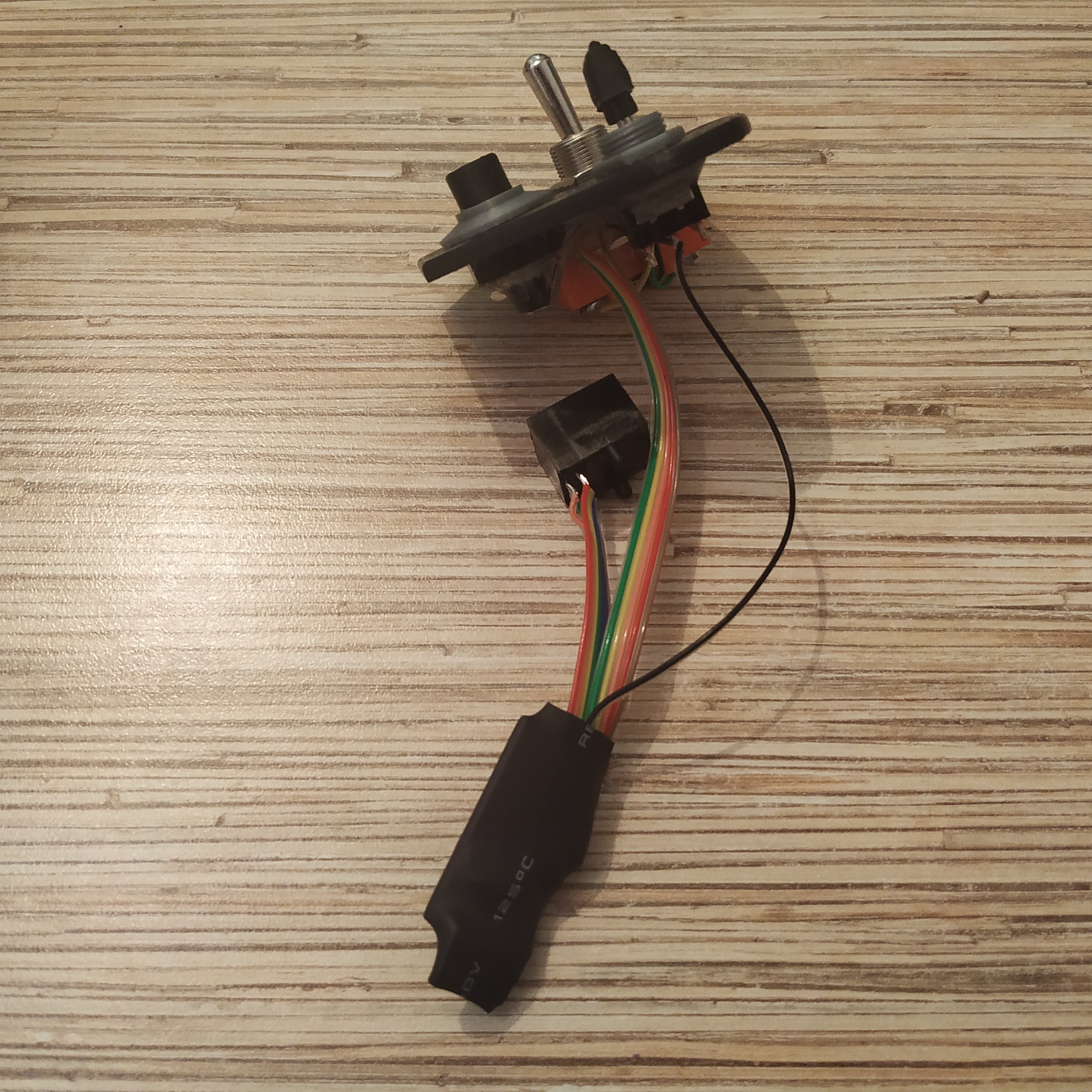
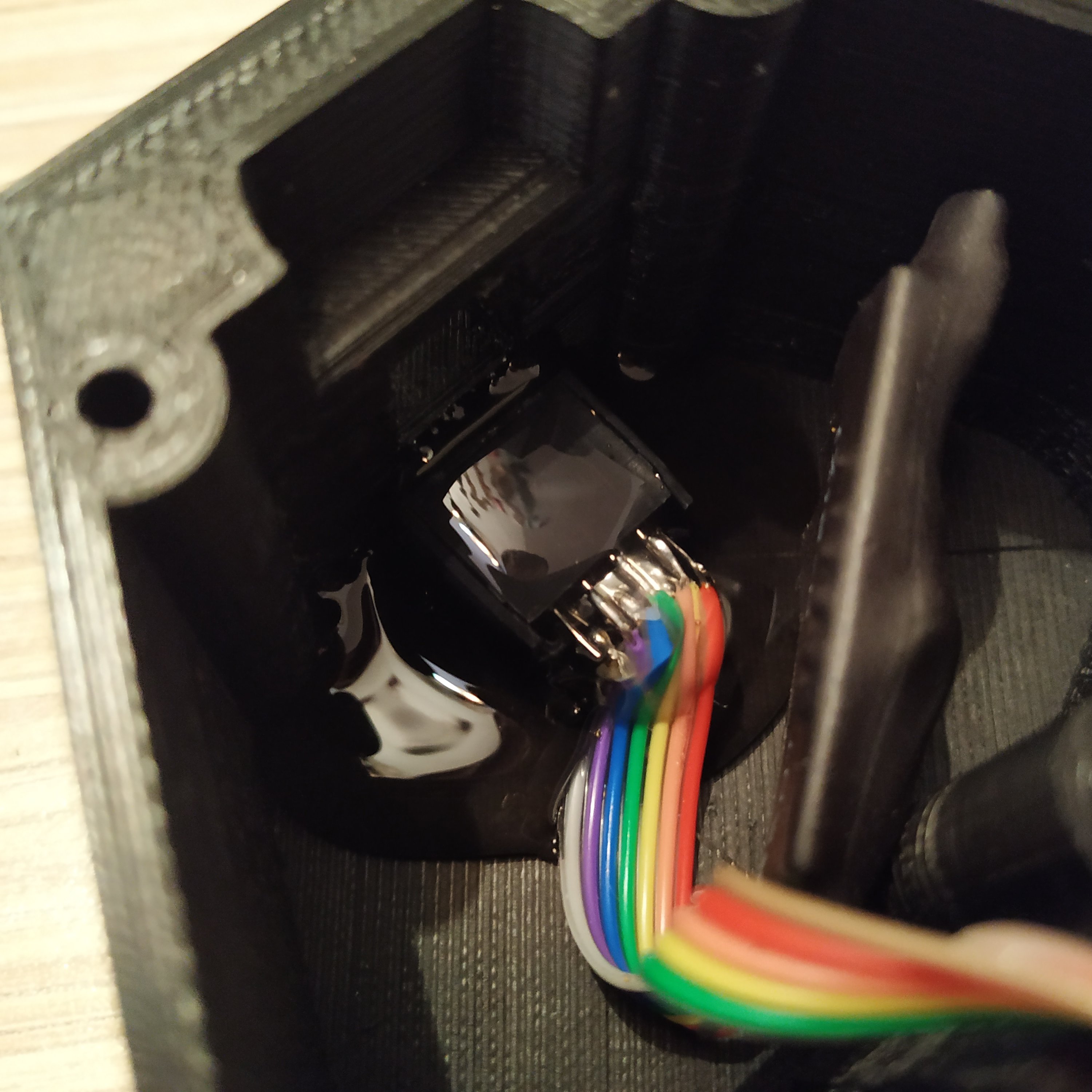
Put a piece of shrink tube onto the board and do some cable management.
5. Flash the head with its firmware, uncomment it in the “device definitions” tab in master controller firmware and check if everything works.
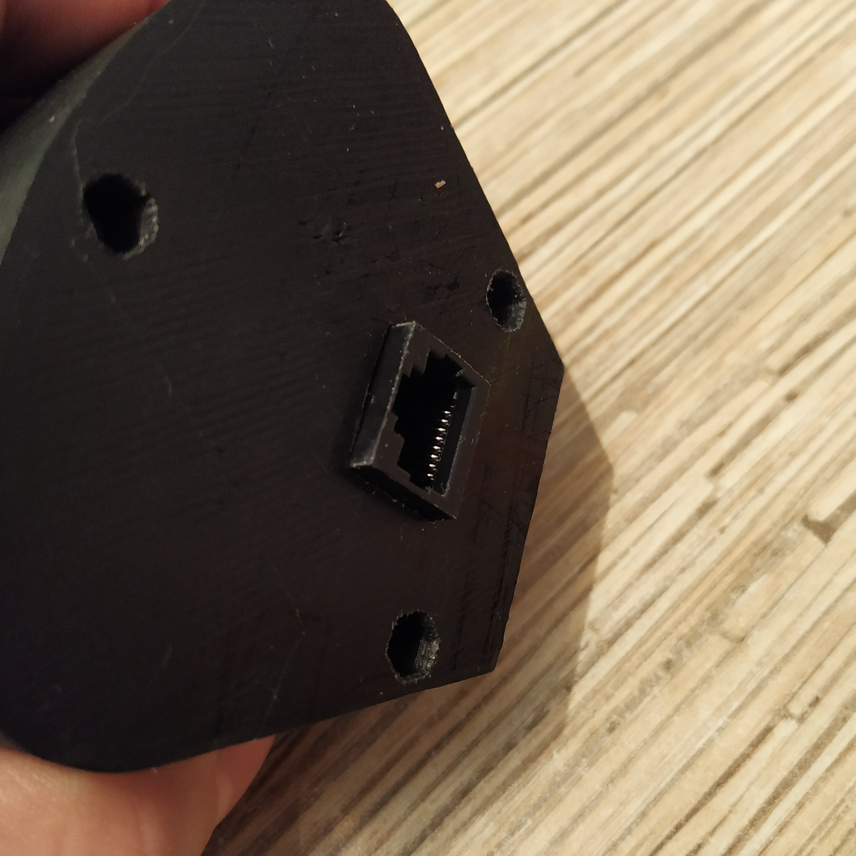
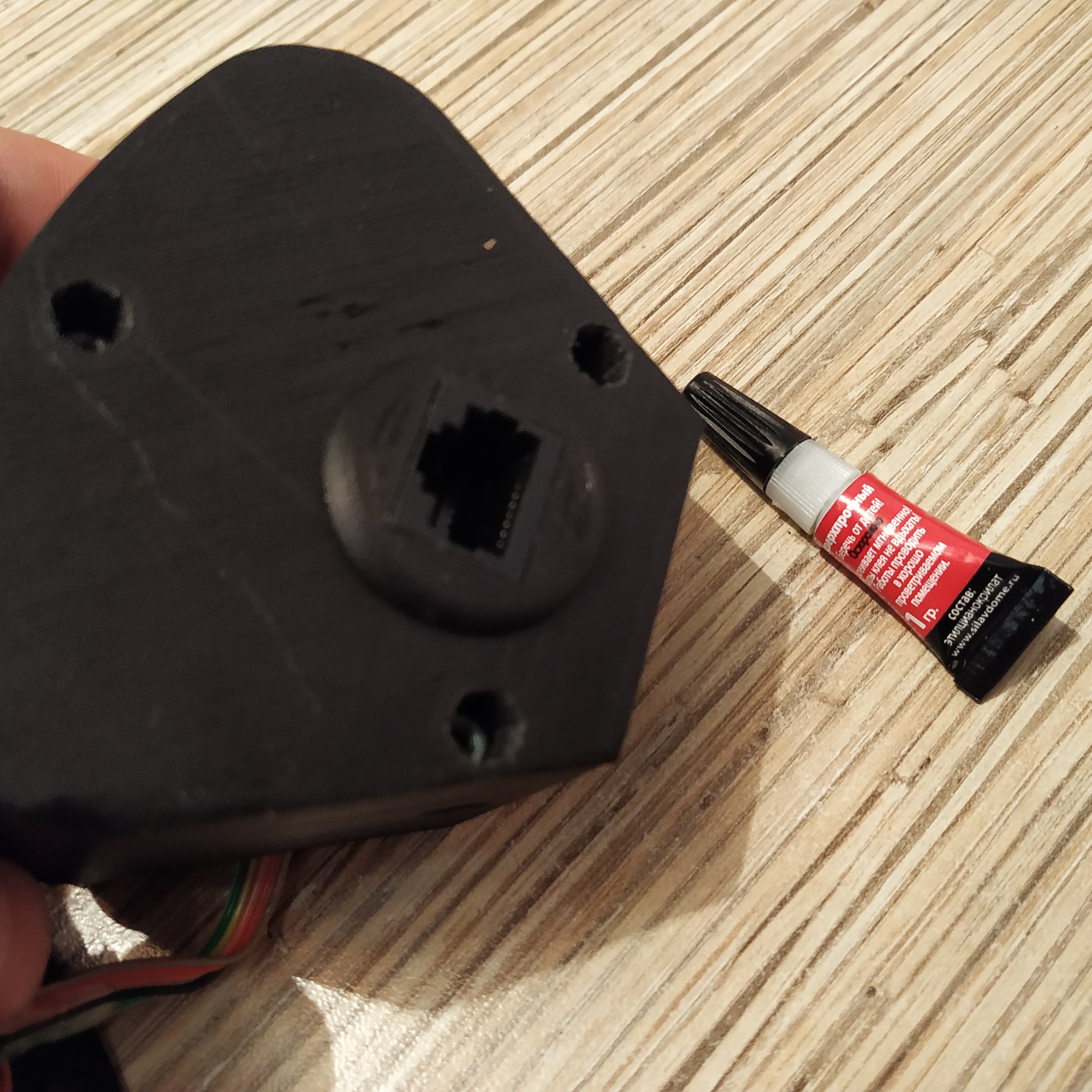
6. Put everything into the box, do some cable management so that the aluminum pipe won't damage wires when the head will be put onto the lever. Push onto the Ethernet socket so it will protrude slightly from the bottom. Glue the socket cap part with some cyanoacrylate and level the socket with it so it will look good. Carefully fix the socket in place with hot glue.
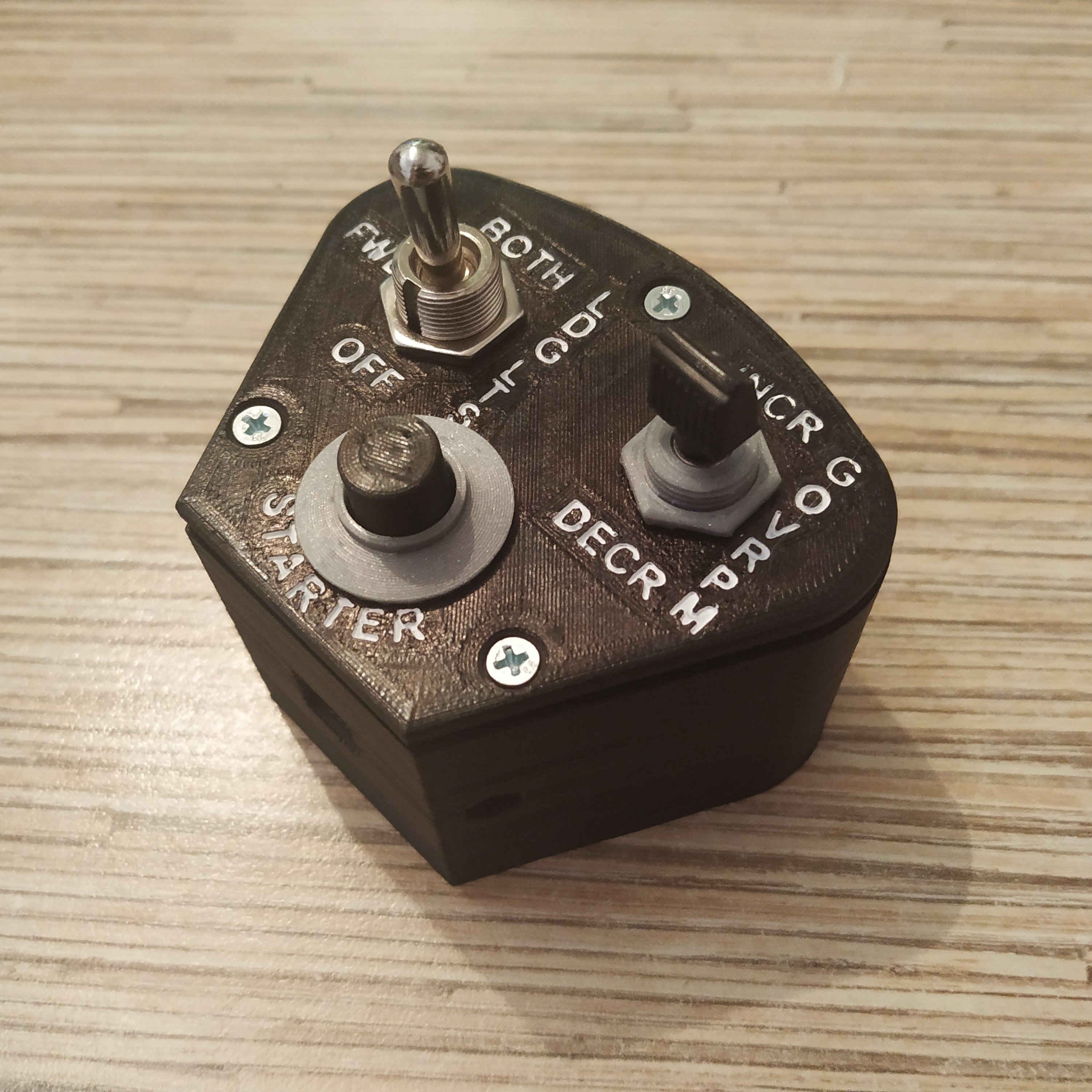
That's it, time to do some flying! ![]()
