Table of Contents
Simple Pedestal
About Pedestals
A pedestal is a device that is mounted onto the collective base to extend its functionality. A few of them are currently available under the MKIV line of hardware.
The recommended default option for flying in VR, is the simple pedestal. If you use radios often, please try this one instead: VRMax II


Summary
The Simple Pedestal for the MKIV collective base is a universal VR mouse replacement device.
It will make your flying experience much better in a simple way.
It features a single knob, emulating the mousewheel and a ministick, to control the cursor – This means that you can control any knob in the cockpit no matter how many of them are there. This also means that you can use your left hand to comfortably operate switches and radios during the flight.
I’ve tried it, and i can say that seriously, this thing is simply epic, and it is definitely one of the highlights of the MKIV line.

Components
- 4 x MTS-123 or MTS-103 switches
- 1 x PEC16-4220F-S0024 encoder
- 2 x PBS-10B2 buttons
- 1 x 6x6x5mm tact button
- 1 x KY-023 ministick board
- 1 x Bourns PTD901-2015K-B103 10K resistor
- 1 x TJ8P8C Ethernet socket
- 4 x M3x35mm screws and nuts
- 4 x M3x10m screws to fix the KY board
- 1 x Arduino Pro Mini
Downloads
Assembly guide
1. Press-fit 4 M3 nuts into the housing.

2. Solder 7-wire cable to an Ethernet socket as follows:

- SOCKET PIN 1 (WHITE-ORANGE wire of Ethernet cable) → 5V
- SOCKET PIN 2 (ORANGE wire of Ethernet cable) → GND
- SOCKET PIN 3 (WHITE-GREEN wire of Ethernet cable) → SCL
- SOCKET PIN 4 (BLUE wire of Ethernet cable) → SDA
- SOCKET PIN 5 (WHITE-BLUE wire of Ethernet cable) → PRO MINI Rx
- SOCKET PIN 6 (GREEN wire of Ethernet cable) → PRO MINI Tx
- SOCKET PIN 7 (WHITE-BROWN wire of Ethernet cable) → PRO MINI DTR

3. Press-fit the socket into the housing

4. Insert the pot into its socket.

5. Install the KY-023 module into the housing

6. Install 4 MTS-123 switches, 2 PBS-10-B2 buttons, encoder and a 6x6x5mm tact button into the lid. Leave bottom nuts on the outermost switches. Fix everything with hot glue. Cut off the excess length of legs of the switches and buttons.


7. Solder the ground wire to all switches and buttons, including 2 pins (one of two pins at the bottom and the middle pin at the top) of the encoder. Note that there's an error on the 1st pic - the GND wire of the pot should be soldered as shown on pic 3!


8. Solder the ISP header to Pro Mini board. Remove the LED on pin 13!

9. Solder GND wire to GND pin next to the reset button on the board, and the RST button wire to RST pin.

10. Solder VCC and GND wires from the socket to the KY stick board, from there route the VCC wire to VCC pin of the Pro Mini board and solder it there.

11. Solder pin 3 of the socket to pin A5 of the Arduino, and pin 4 to pin A4.

12. Solder wires 5,6,7 to RXd,TXd, DTR on the Arduino board.

13. Solder a 3-wire cable between pins VRx, VRy, SW of the pot board to pins A6, A7,RX1 of the Pro Mini.

14. The Lid:
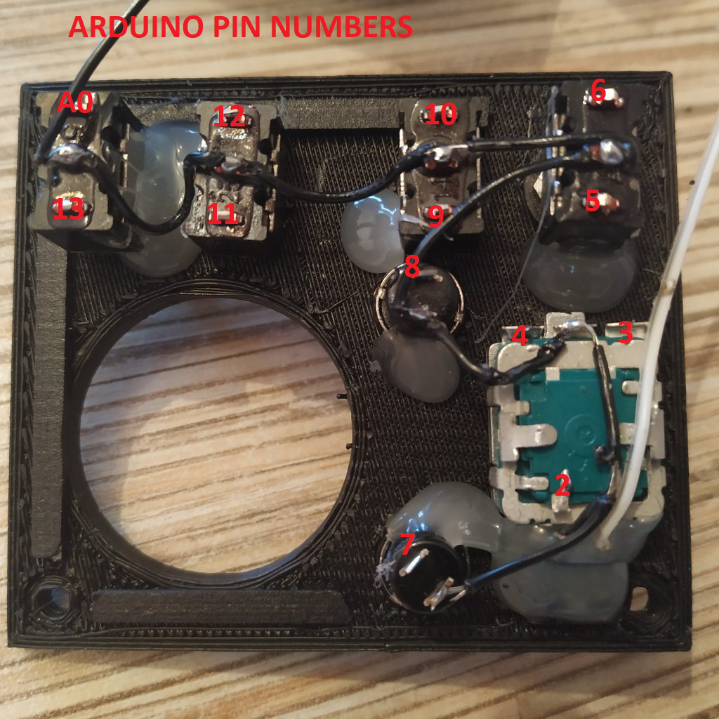
Solder the switches, buttons, and the encoder, as follows (Use a 13-wire cable):


15. Solder the potentiometer with a 2-wire cable. Connect leftmost wire to 5v, the middle one – to A3.

16. Check that everything looks correct. Flash the board with the firmware using a FT232TL based adapter (or any other) and a UART- Ethernet cable. Connect it to the master controller and check that everything works. If everthing is ok, proceed, otherwise go back, and check your connections, and that the LED on pin 13, was really removed!
17. Close the lid. Fix it with 4 M3x35mm sxrews, put the knobs on. When attaching the zoom axis knob, center the pot as shown on the picture below:


18. Calibrate the ministick: To do this, uncomment the following lines in the g_simple_pedestal tab of a_master.ino (master controller sketch):
Serial.print(x);
Serial.print(" ");
Serial.print(y);
Serial.print(" ");
Serial.println(enc);
and check the serial port output.
Open configuration tab and set // Ministick to
#define X_CENTER 128
#define Y_CENTER 128
to whatever values you will see. (1st one is X, 2nd one is Y, 3rd one is the encoder). Comment stuff  again and reflash the master controller board.
Check that the pointer works good, and adjust the sensitivity setting to your liking:
#define MINISTICK_SENSITIVITY_LOW 5
#define MINISTICK_SENSITIVITY_HIGH 15
You may want something like low 1 and high 5 if the collective is your only device, and higher values if the board has a lot of stuff connected to it. Reflash the board again and check if pointer speed satisfies you, repeat the process if necessary.
Congratulations, your pedestal is finished! :)
