This is an old revision of the document!
Table of Contents
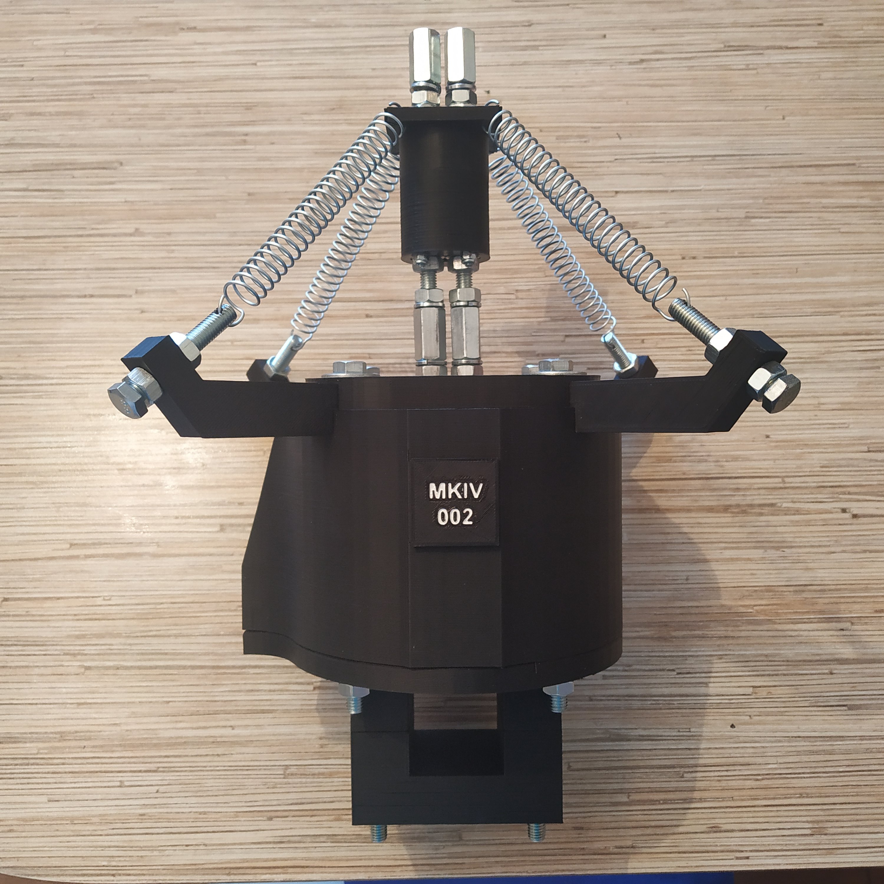
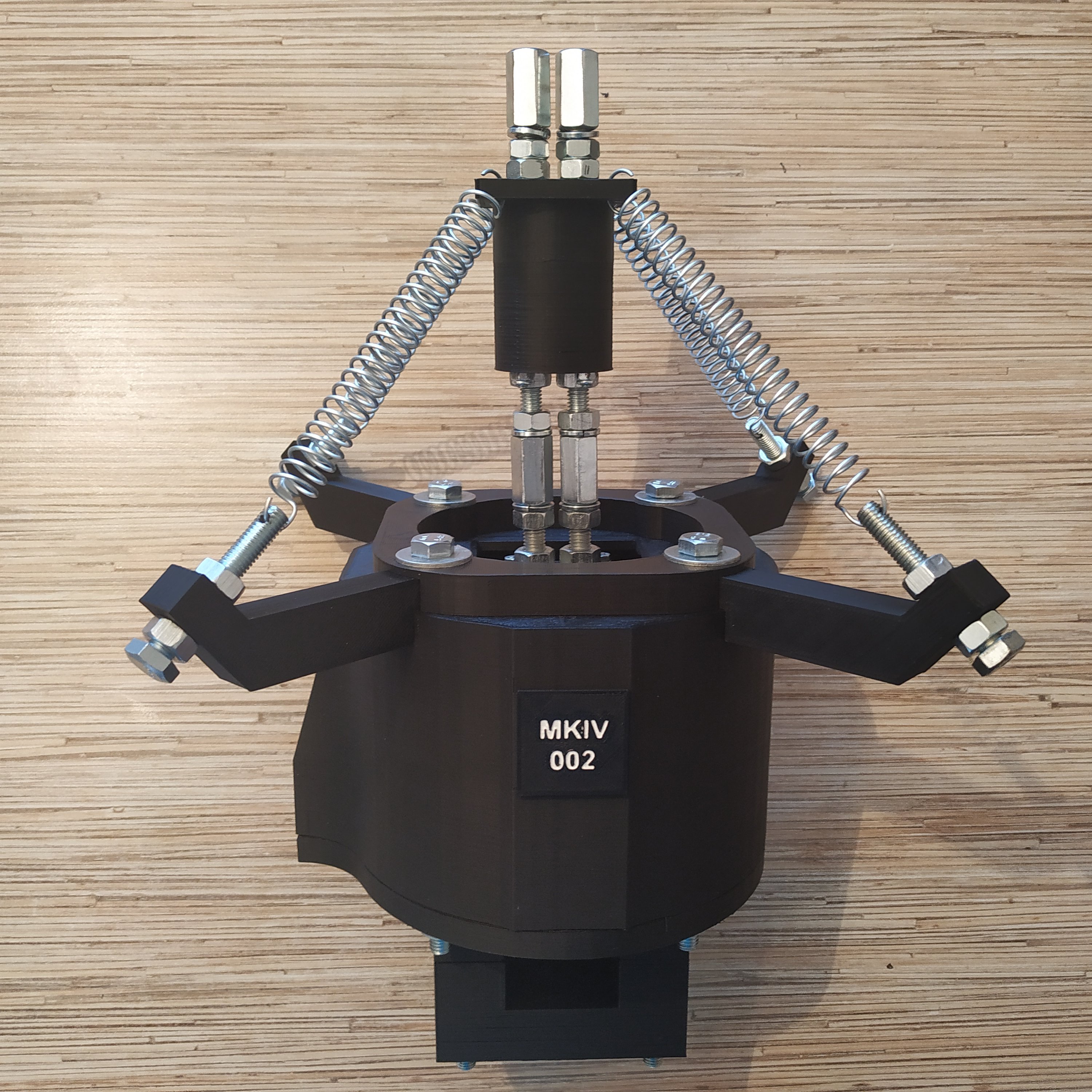
Simchair MKIV cyclic base
Summary
It is a cyclic base, designed to simulate movements a pilot does in a real helicopter. A regular desktop joystick should be tilted to an angle around 40-45 degrees to reach max or min values of its axes, while in a real heli you barely have to move the stick to fly, its more like applying pressure to it, so the nature of movements differs a bit and is closer to reality when you have a long stick. Also, the way that centering is implemented in most joysticks causes movements around the center to be less precise due to noticeable “bump” when going through the center. In this gimbal, centering is made in a different way to avoid this “bump” entirely.
This gimbal can be mounted to the frame under the IKEA GUNDE chair, in a way you won’t even notice it is there when you’re not flying. The detachable stick allows you to take it off quickly when you don’t need it, serving the same purpose.
This cyclic is designed to be operated with springs for stick centering, and has a built-in force trim system (also works with simchair pedals) and stick sensitivity/rates control panel that allows you to fine-tune it for every helicopter with a turn of a knob.
Components
- 2 x SS495A1 Hall effect sensors
- 2x 6x6x4mm magnets
- 4x M8x60mm bols
- 6x M8x50mm bolts
- 4x M8x75mm bolts (optional, depends on the chosen mount!)
- 4x M8x140mm bolts
- 32x M8 regular washers
- 4x M8 reinforced washers (wide ones)
- 14x M8 spring washers
- 34x M8 nuts
- 4x M8x25mm connector nuts
- 2x M6x40mm HEX(!) bolts
- 1x M6x80mm HEX(!) bolt
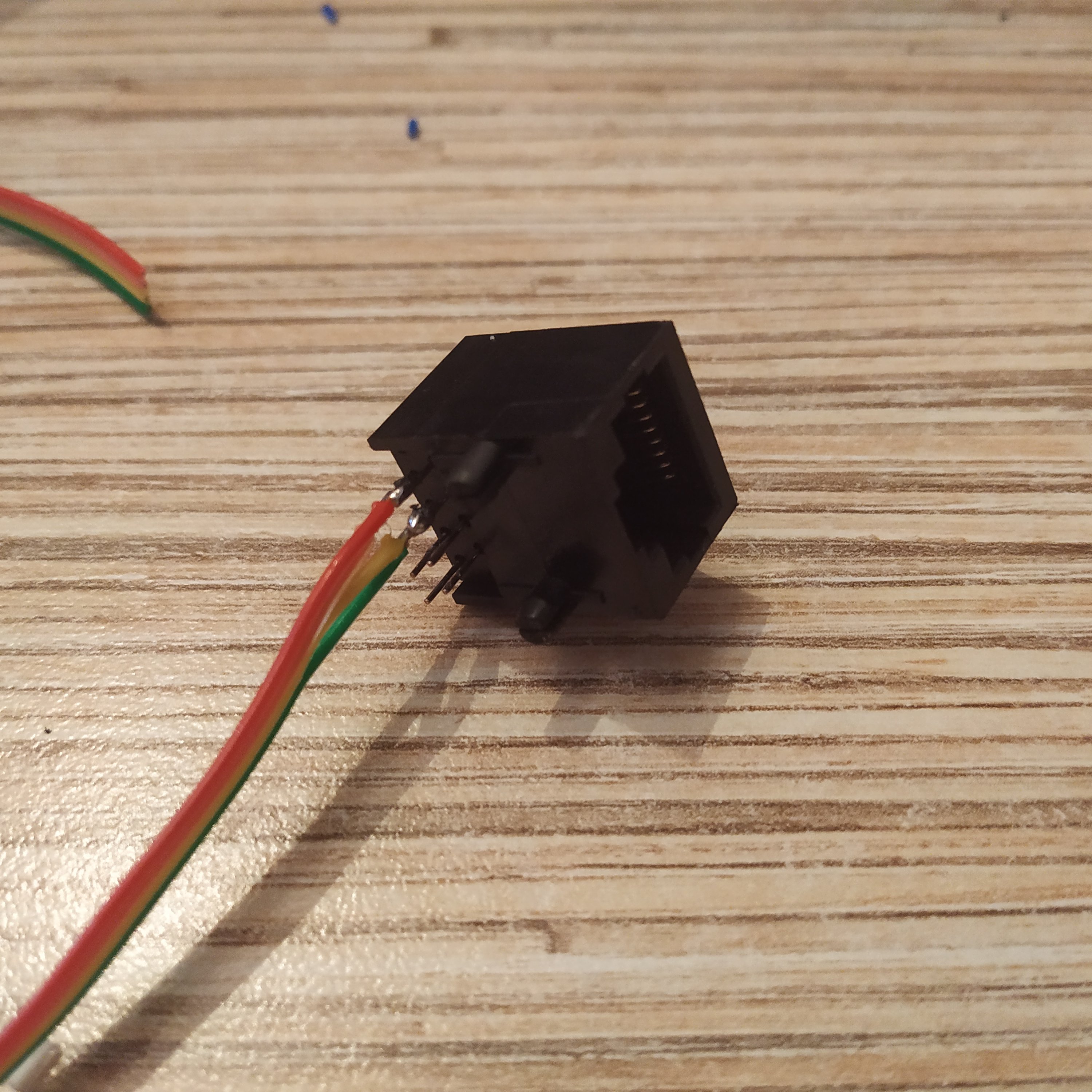
- 2x M6 regular washers
- 4x M6 reinforced washers (wide ones)
- 4x M6 nuts
- 24x M4x40mm screws
- 4x M4x50mm scews
- 4x M4x60mm screws
- 16x M4 regular washers
- 4x M4 nyloc nuts
- 32x M4 nuts
- 4x M3x50mm screws
- 8x M3 washers
- 4x M3 nuts
- 4x 18x6x8mm cylinders
- 8x 608zz bearings
- 3x TJ8P8C Ethernet sockets (12,5x15x17,6mm)
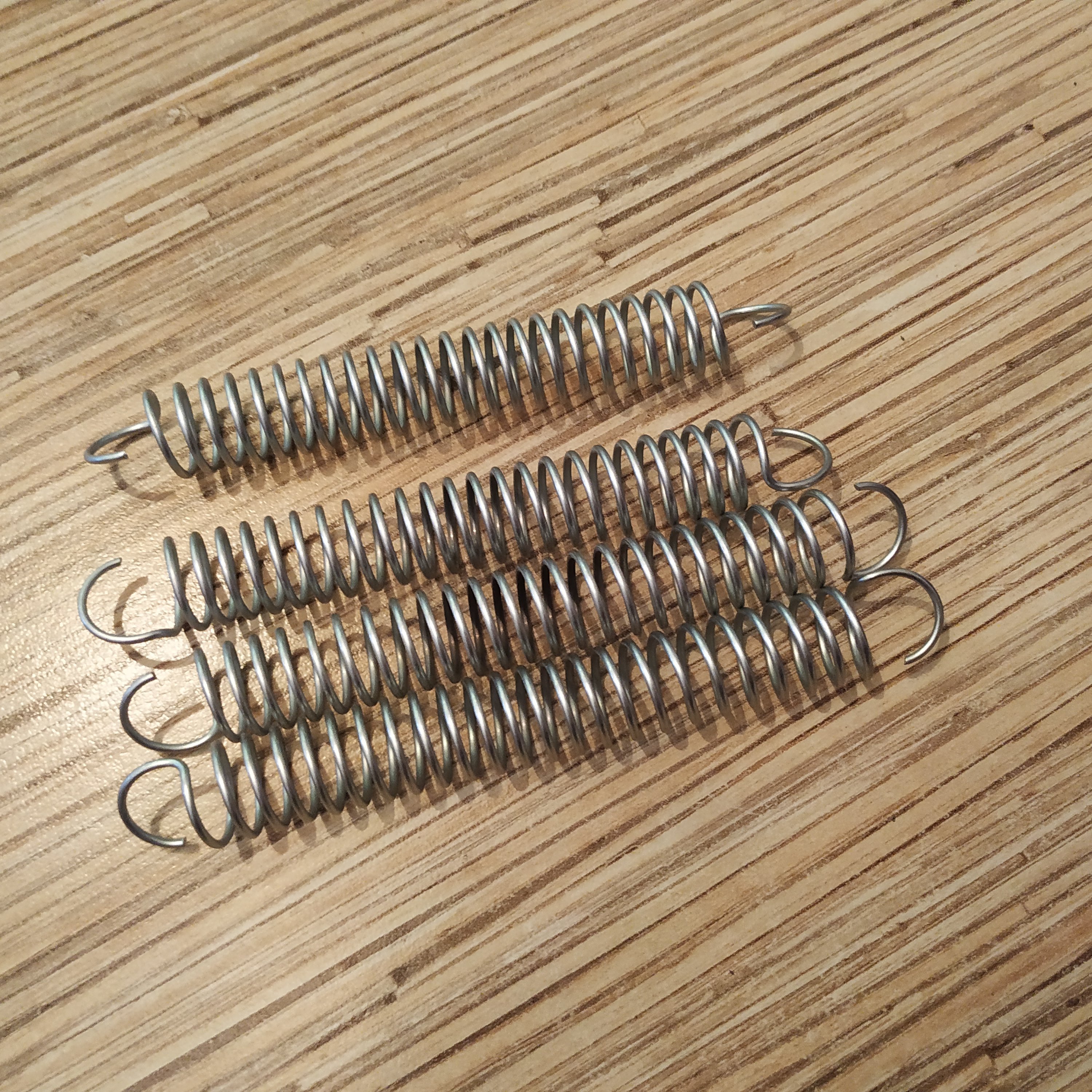
- 4x Sicmhair cyclic springs
Note: All bolts used are hex head bolts
Repository path
simchair4_models\printable components\peripherals\helicopter\collective lever\a_base - models
simchair4_software\peripherals - choose the preferred variant of the lever - software
Assembly Guide
We will start by putting the gimbal rings assembly together.
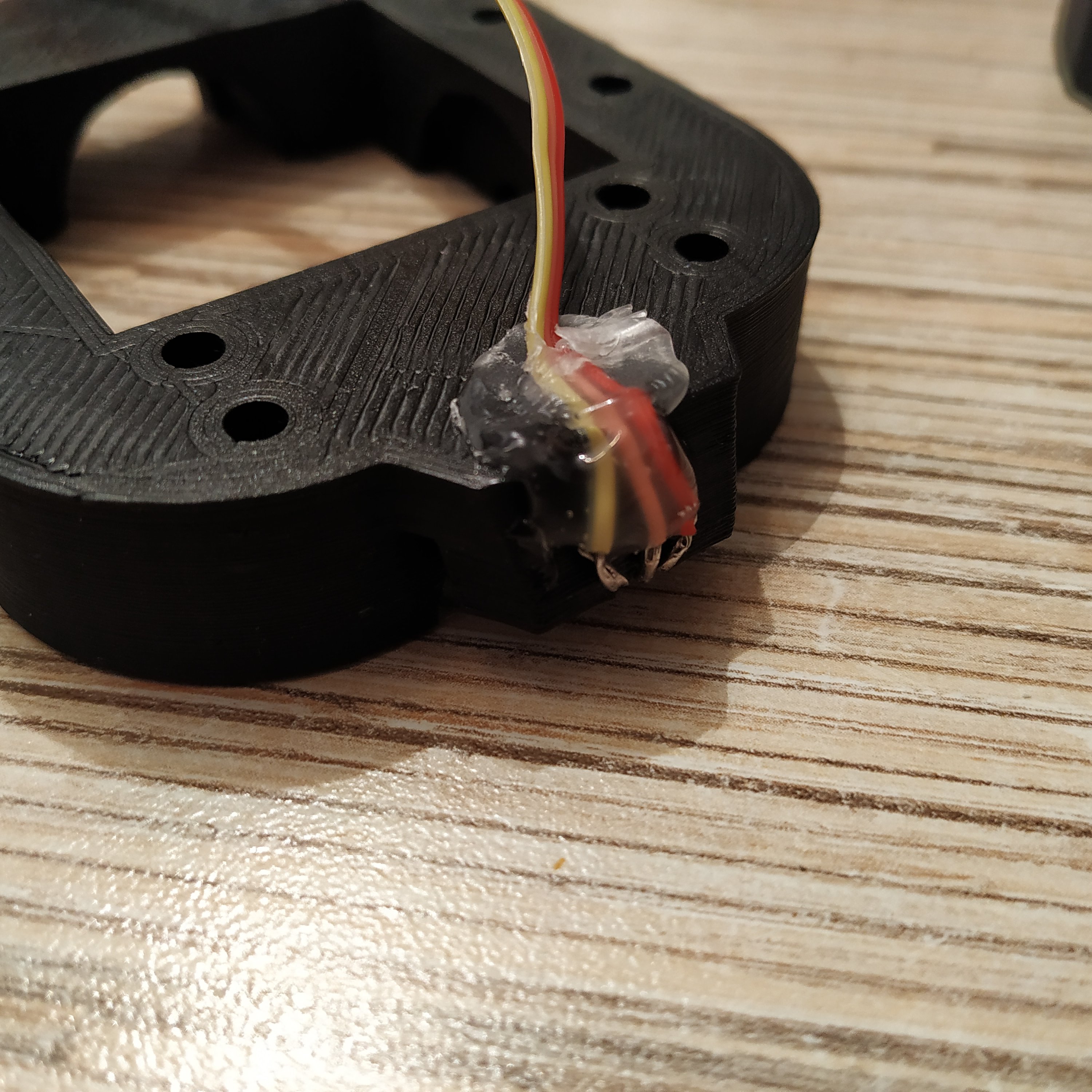
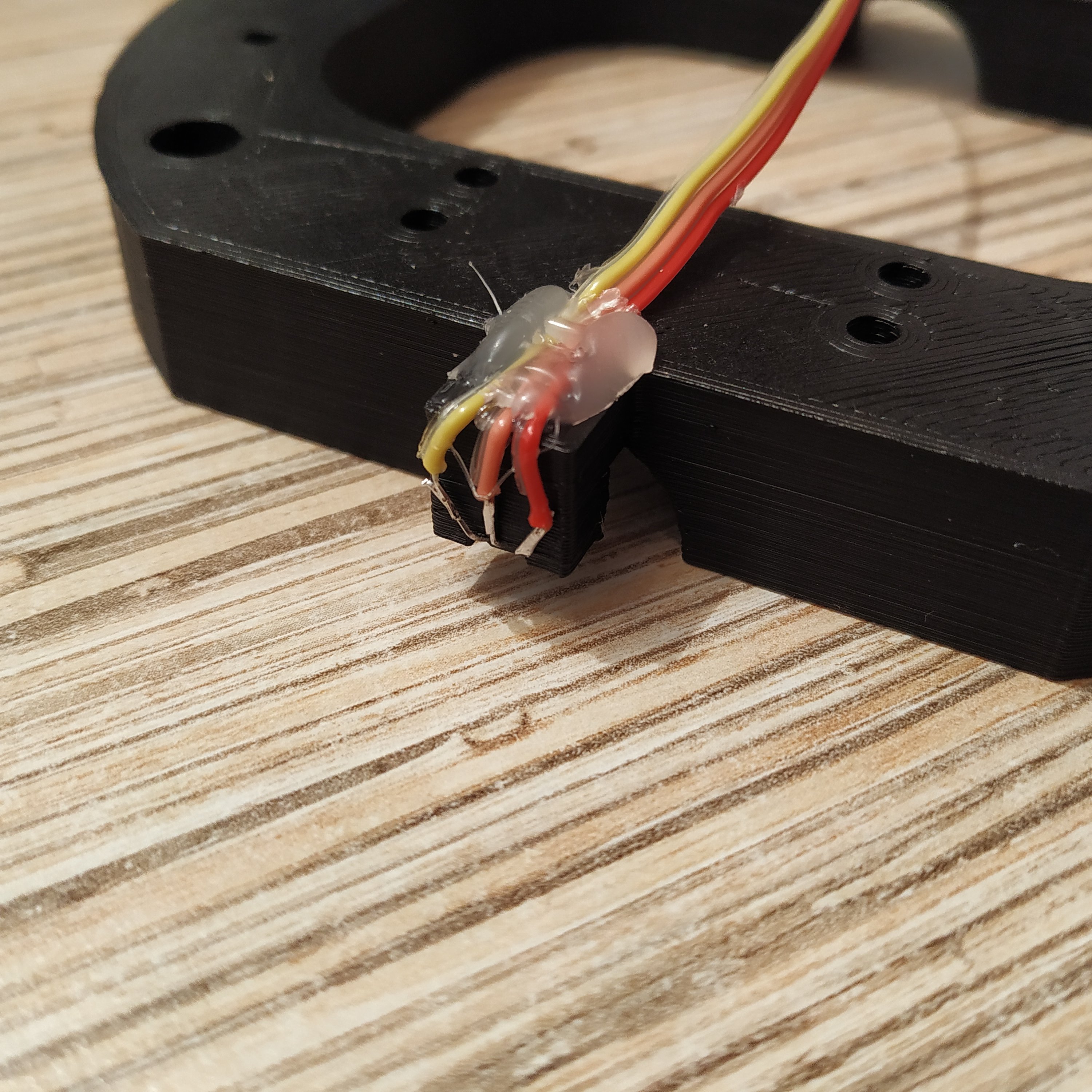
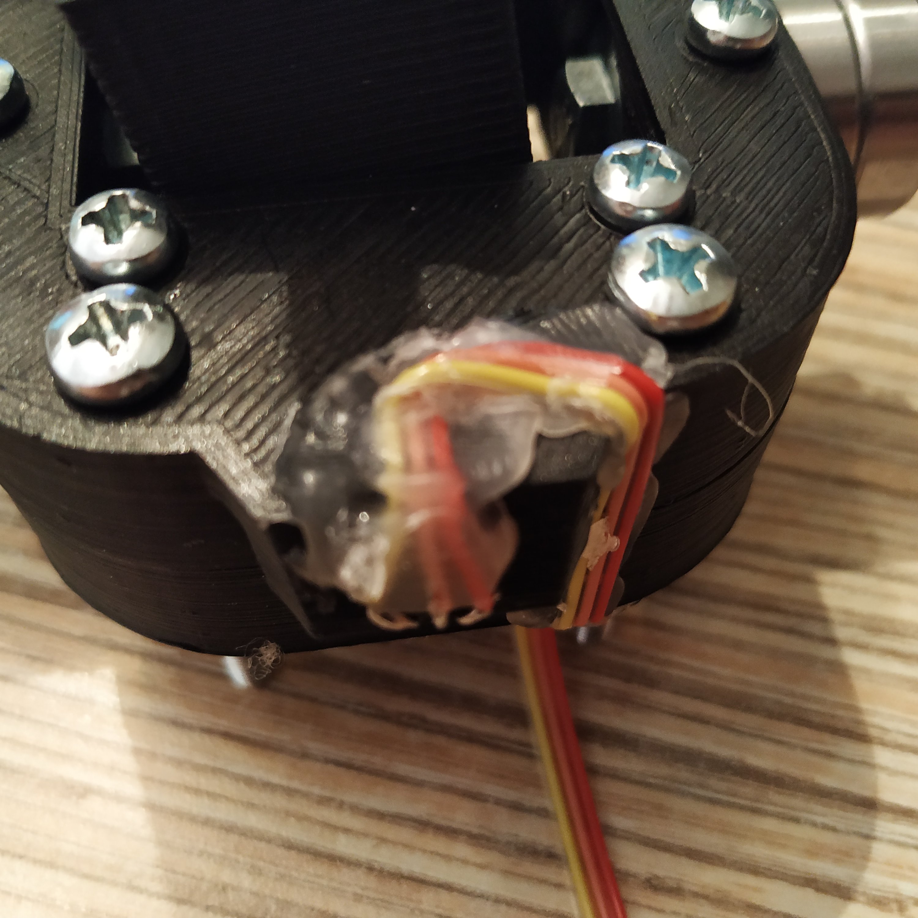
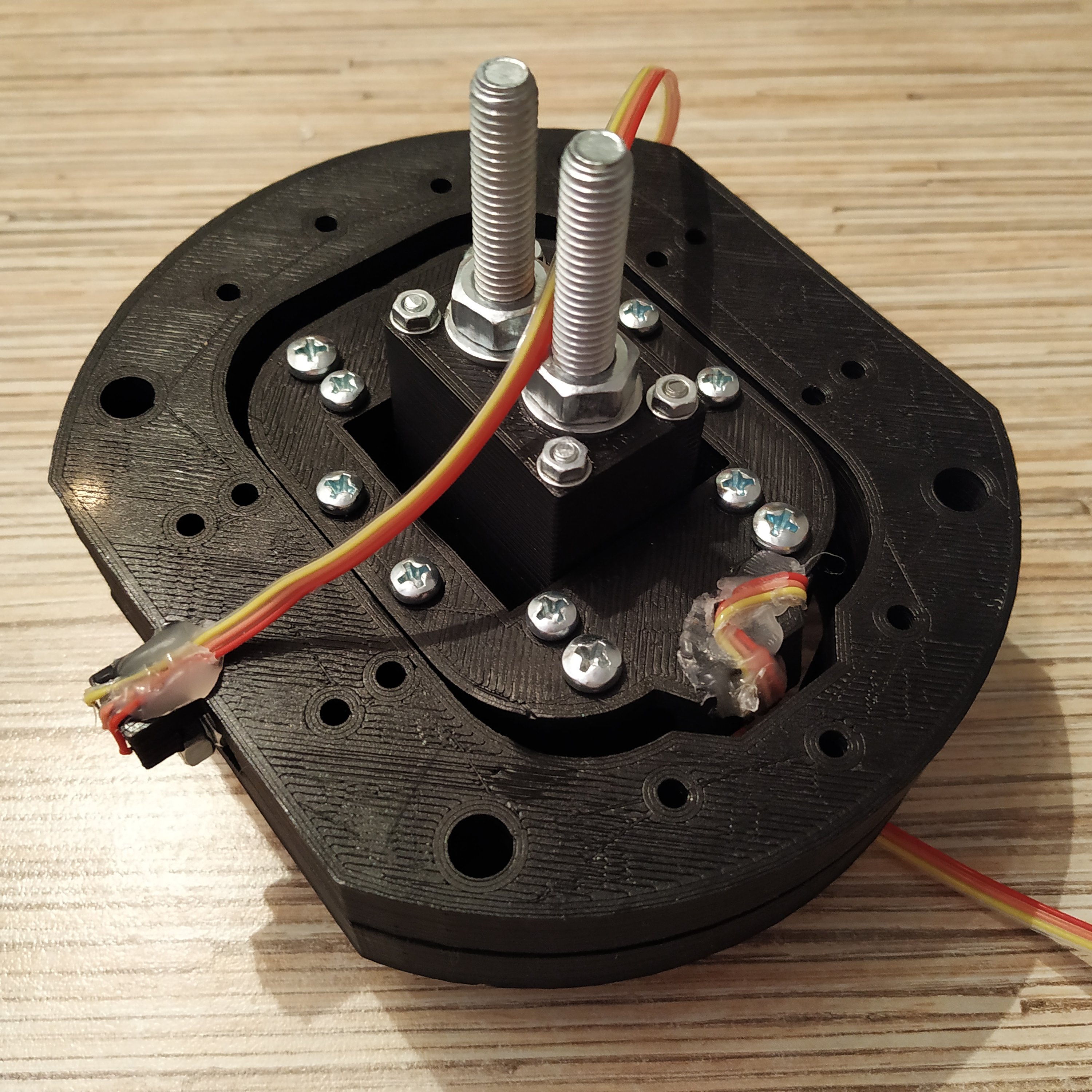
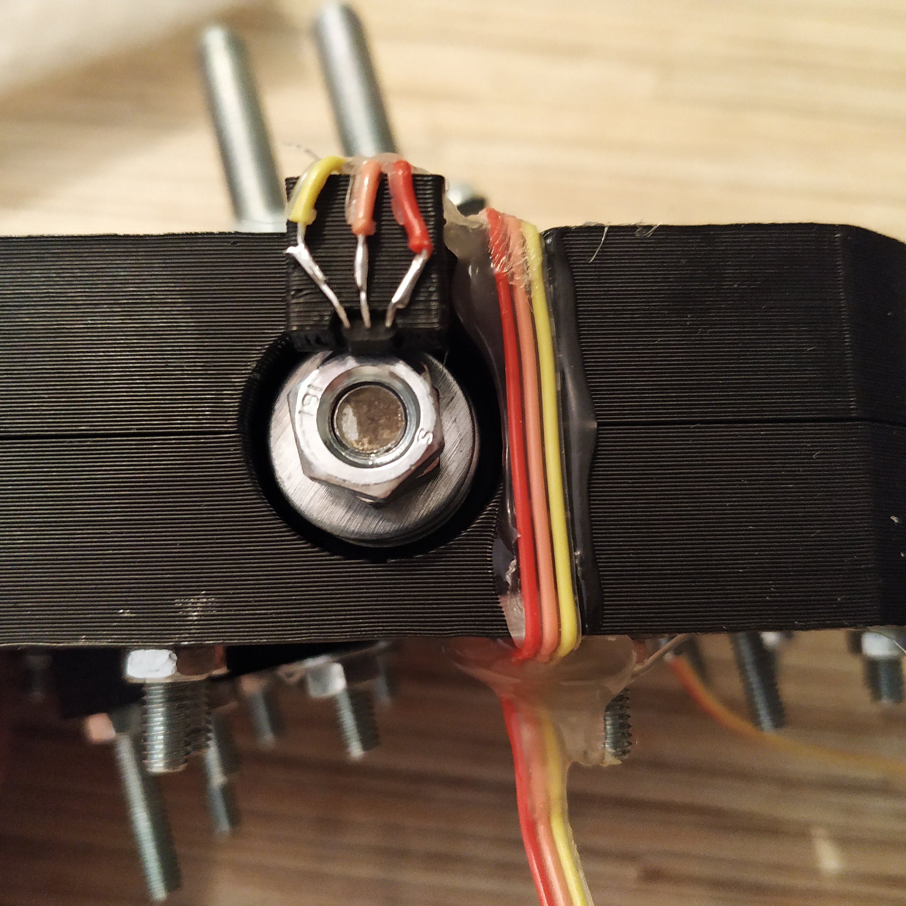
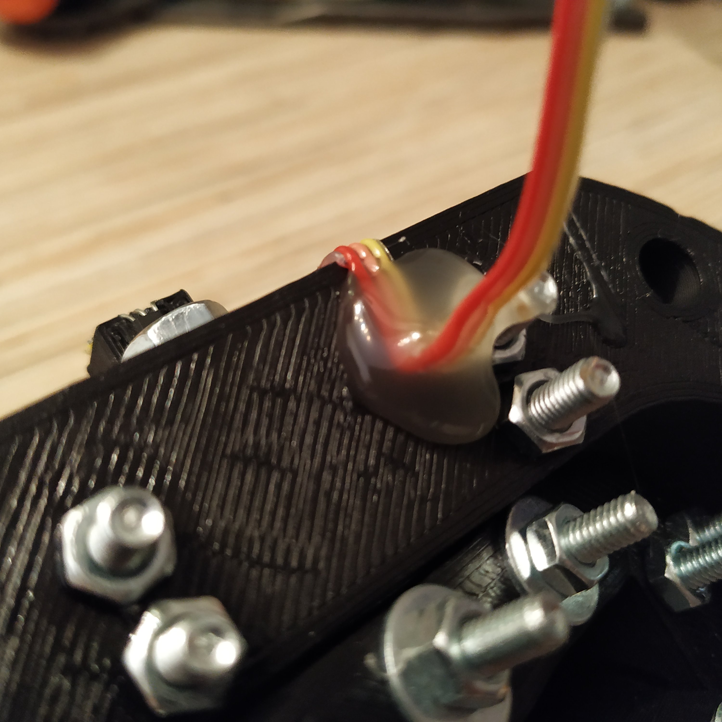
1. Put SS495A1 sensors into their sockets. Solder their wires and fix them in their sockets with a drop of cyanoacrylate glue. Cut off the excess length of sensor legs and fix wires with hot glue.

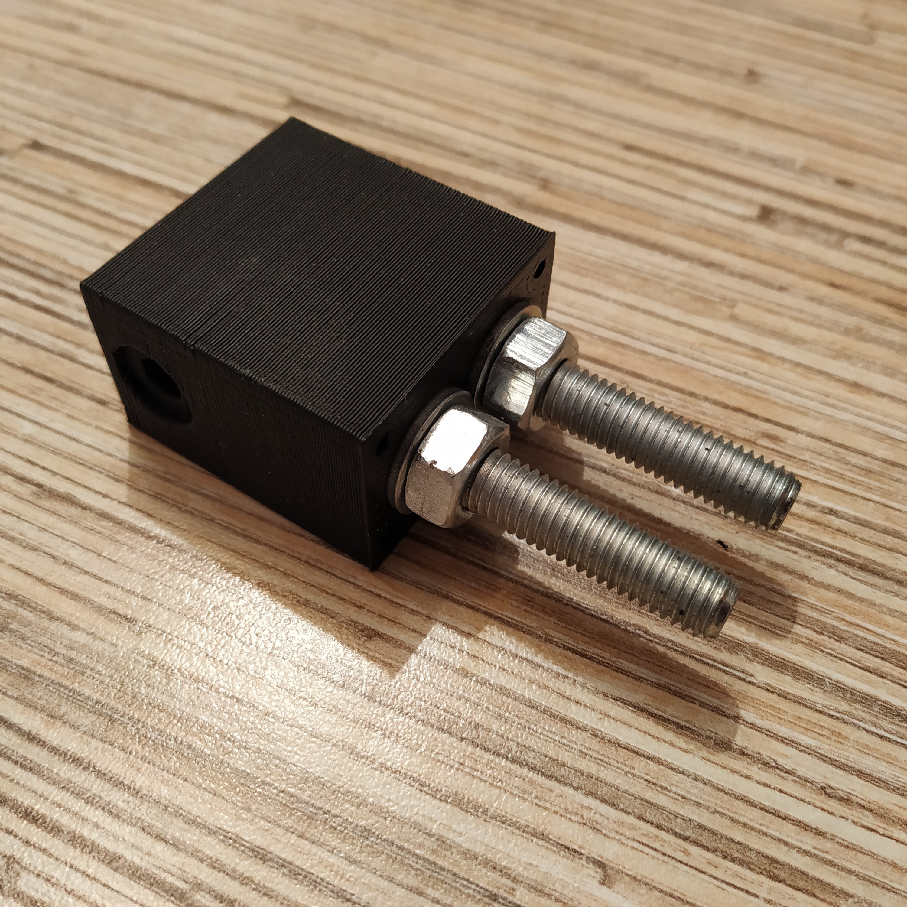
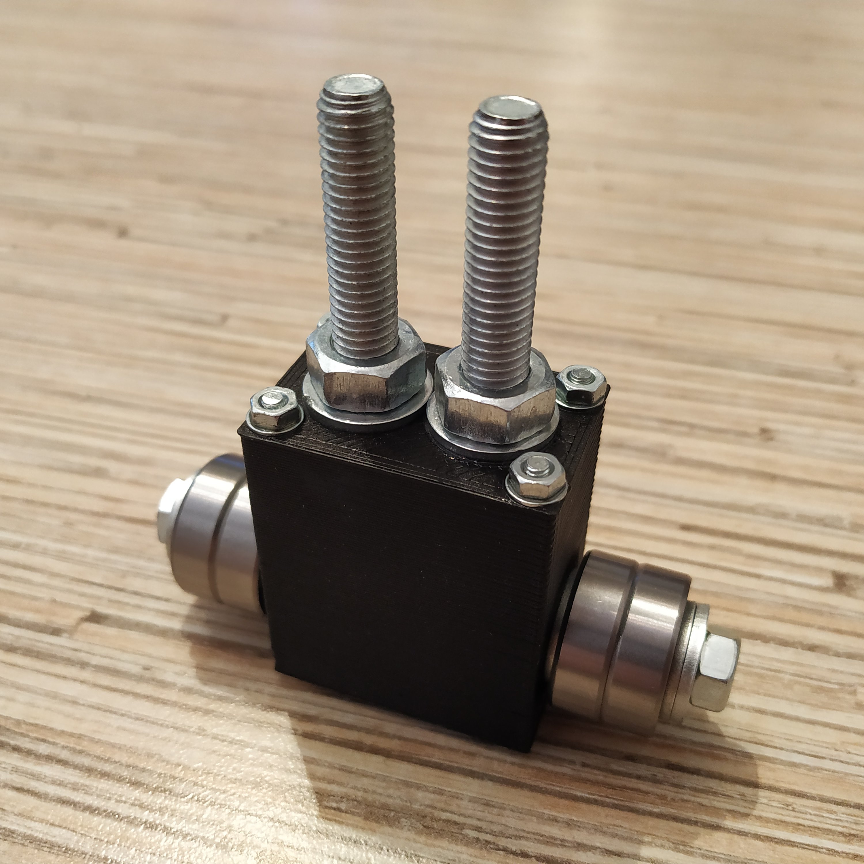
2. Insert 2x M8x60mm bolts into the lever connector part, put 2 M8 washers and nuts on the other side. Those bolts should be a very tight fit so tighten nuts to press-fit them. Put the lid onto the lever connector part. Fix it with 4 M3x50MM screws, use washers on both sides. Use thread locker to fix nuts.

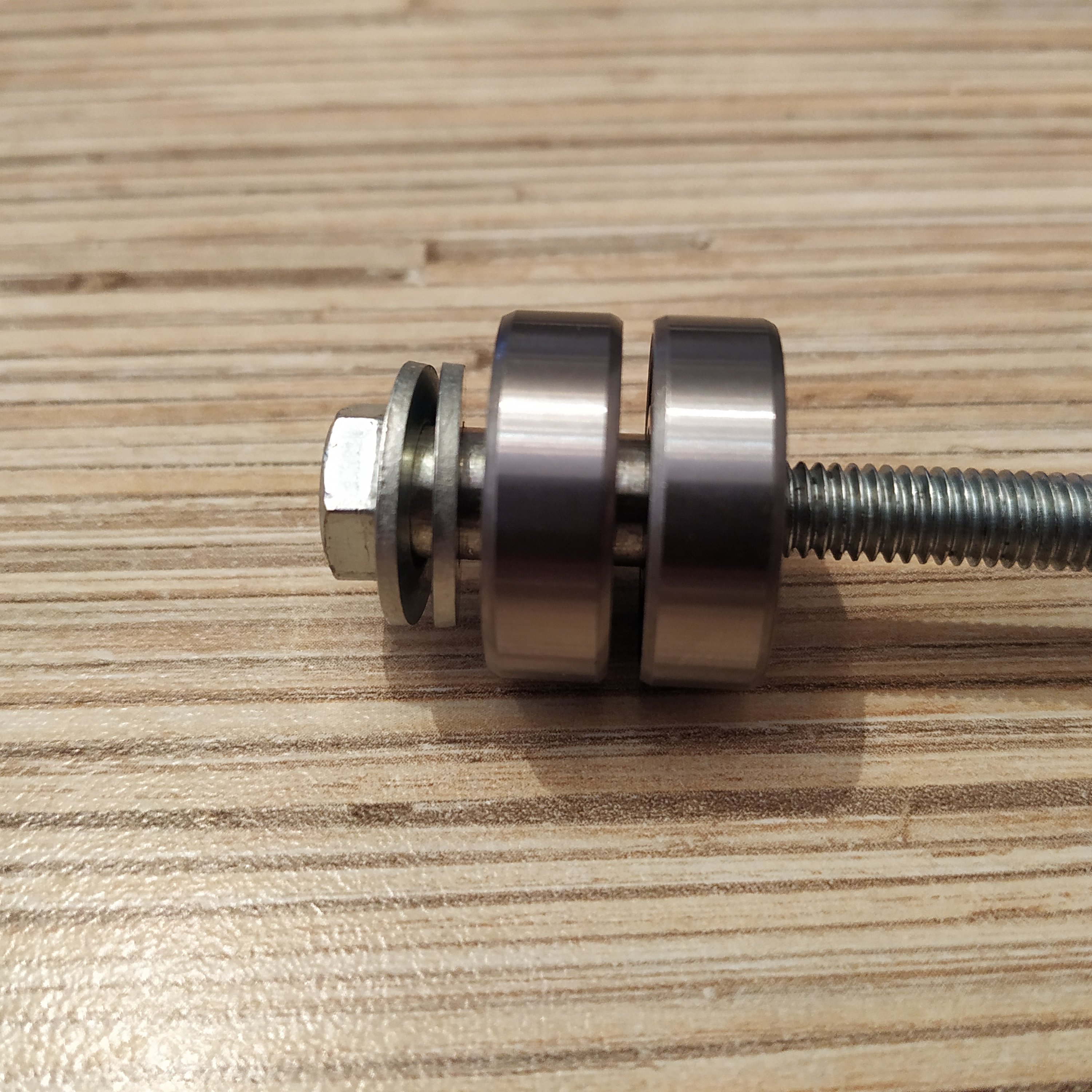
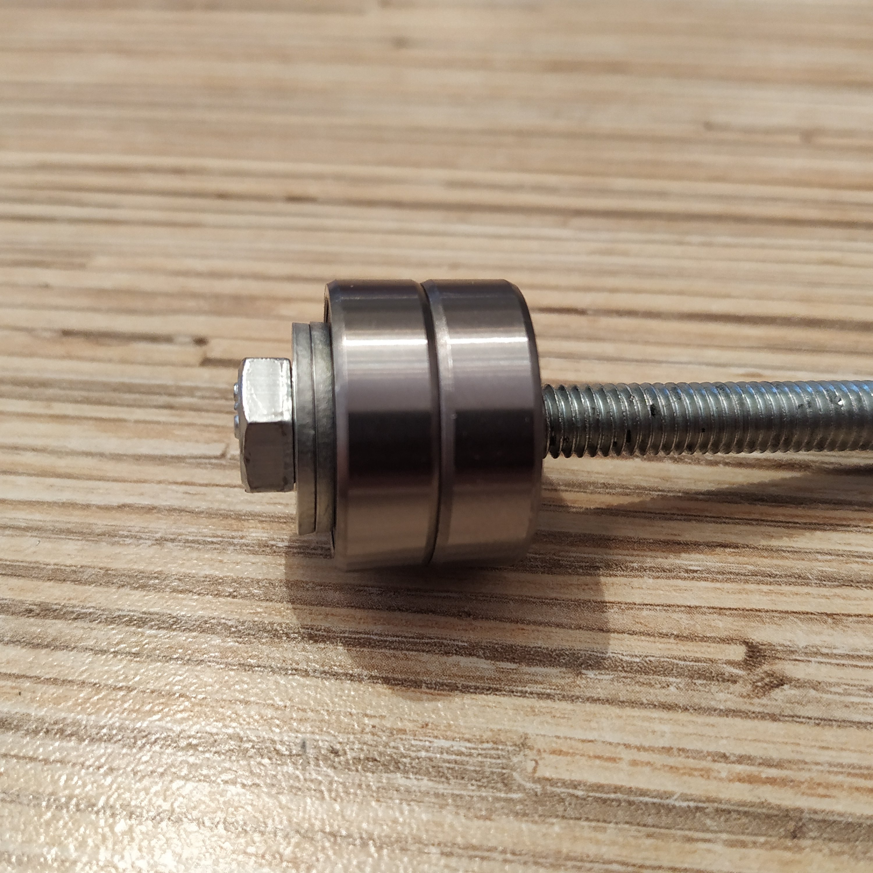
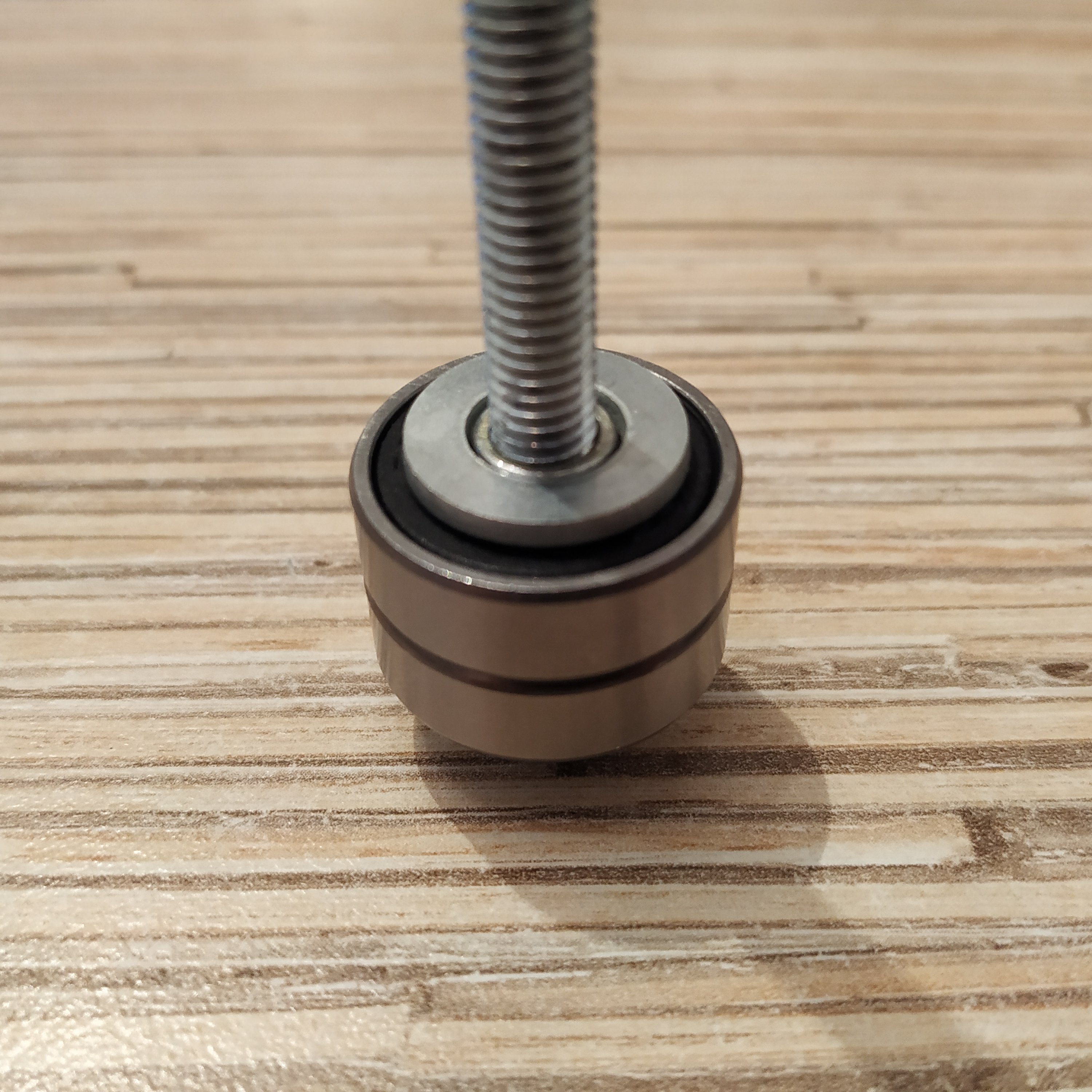
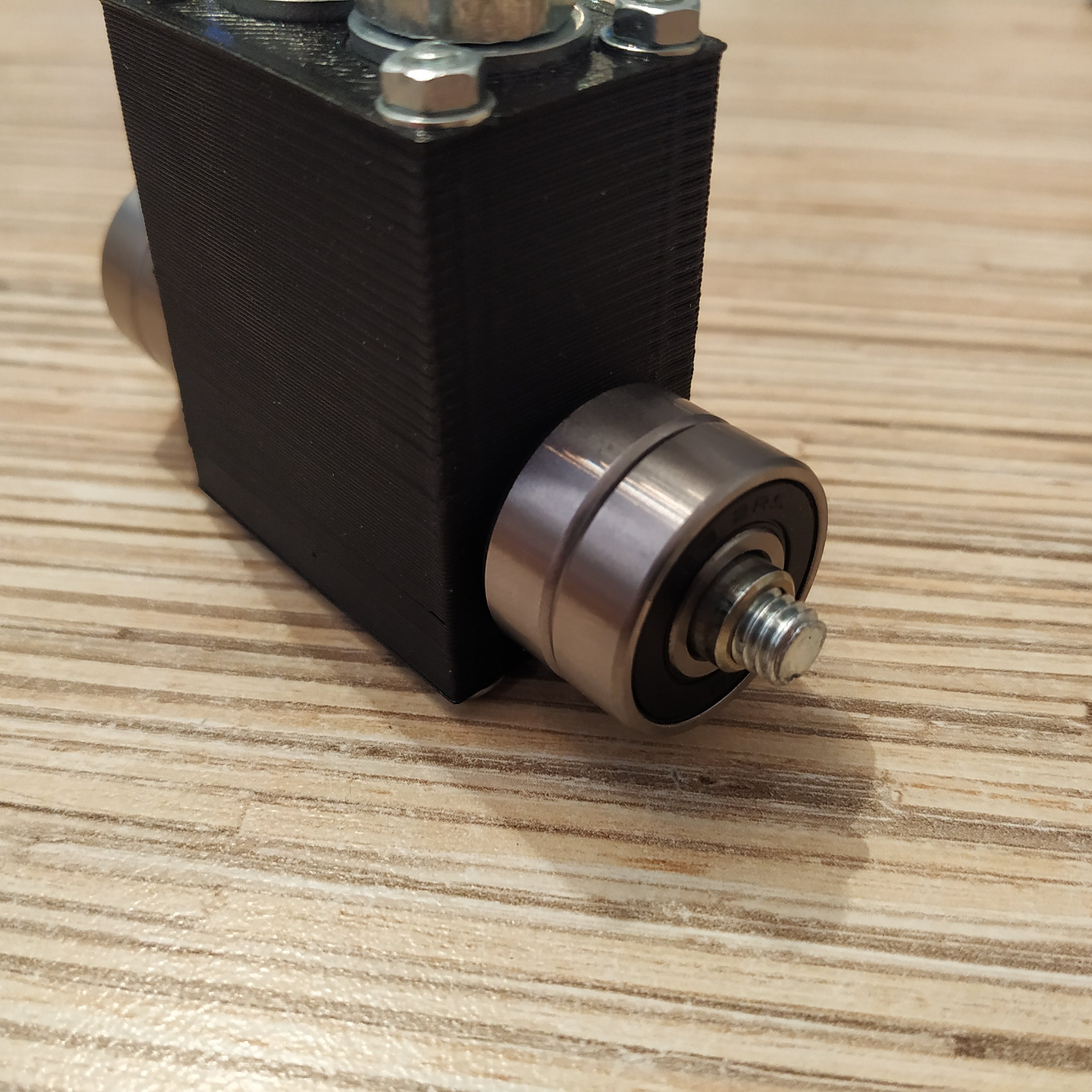
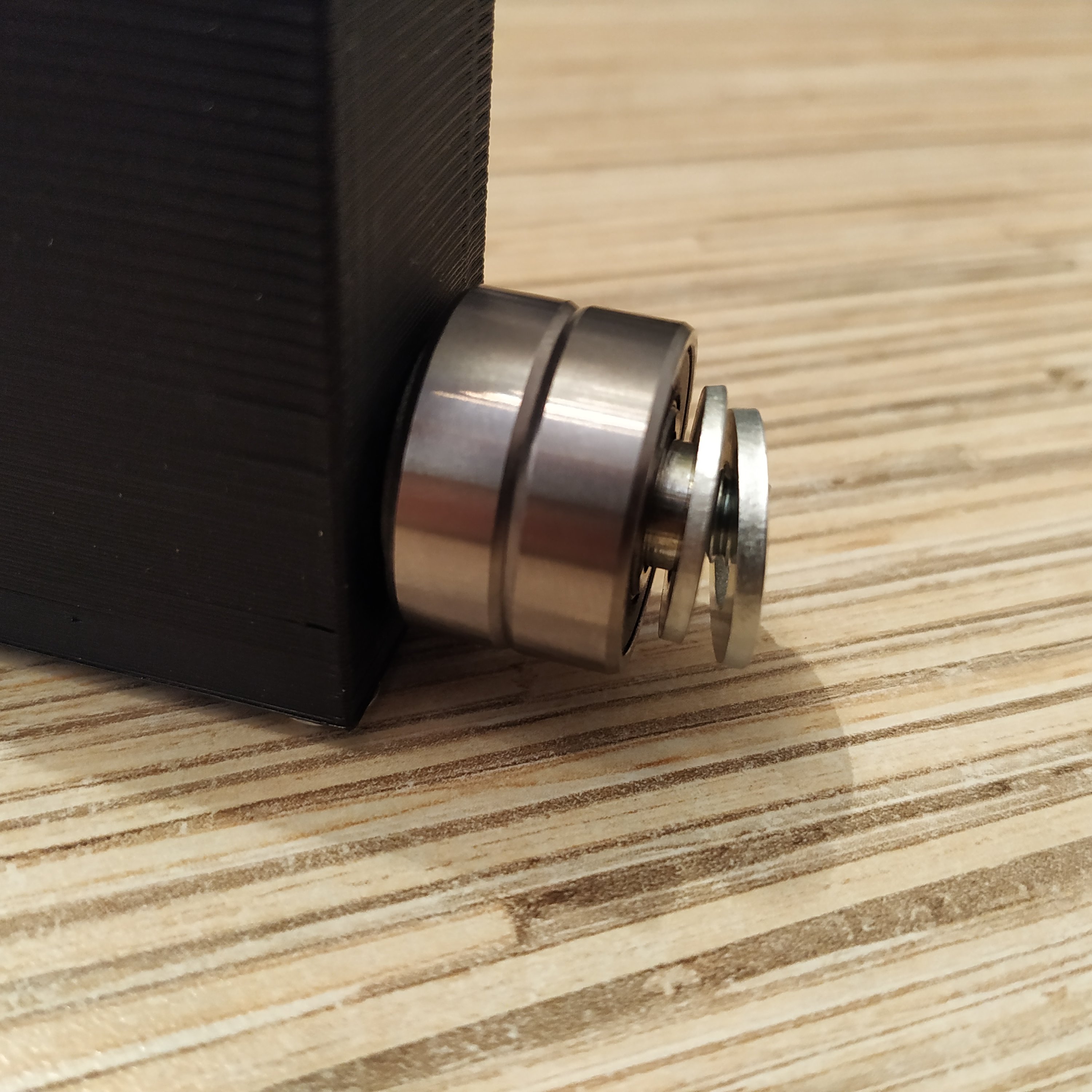
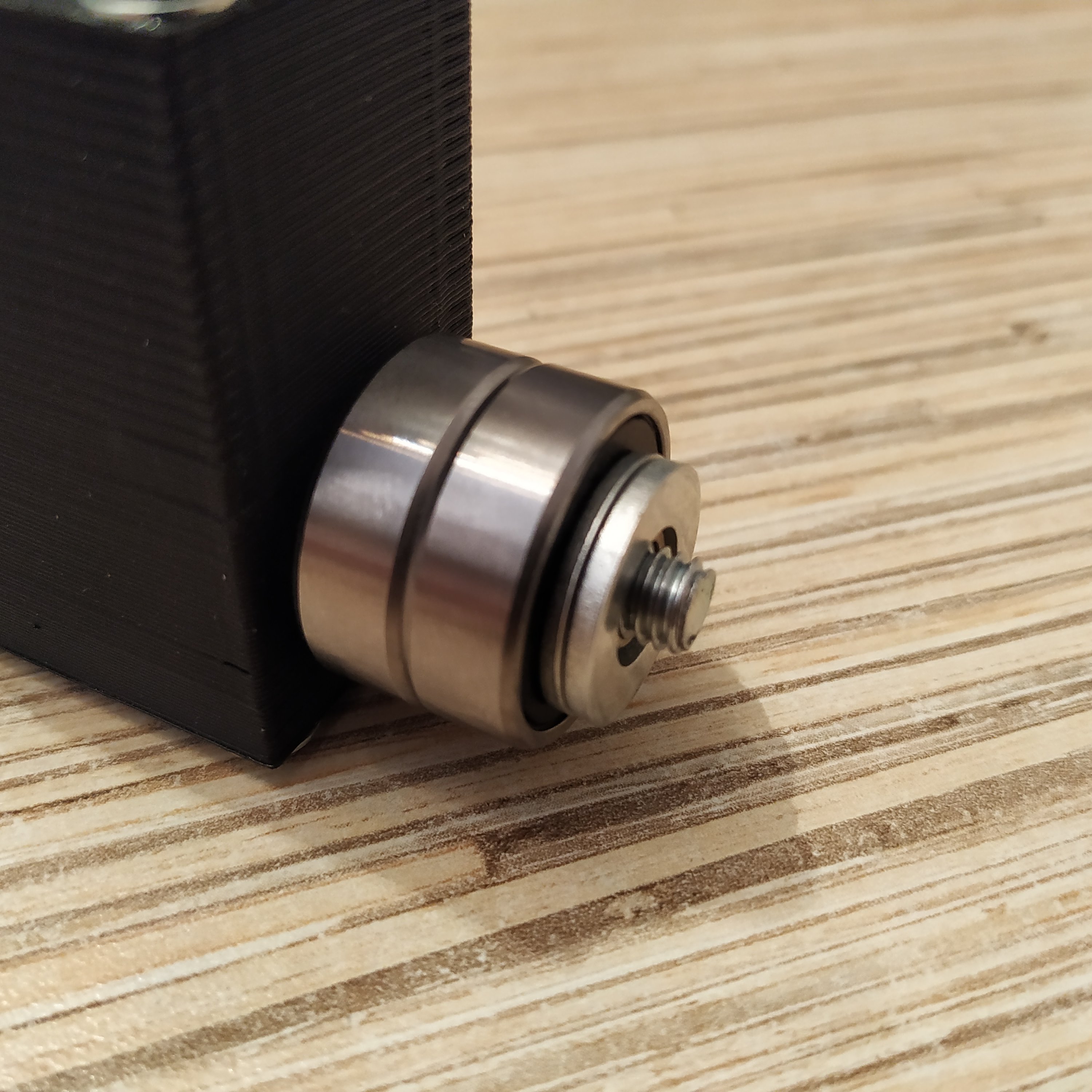
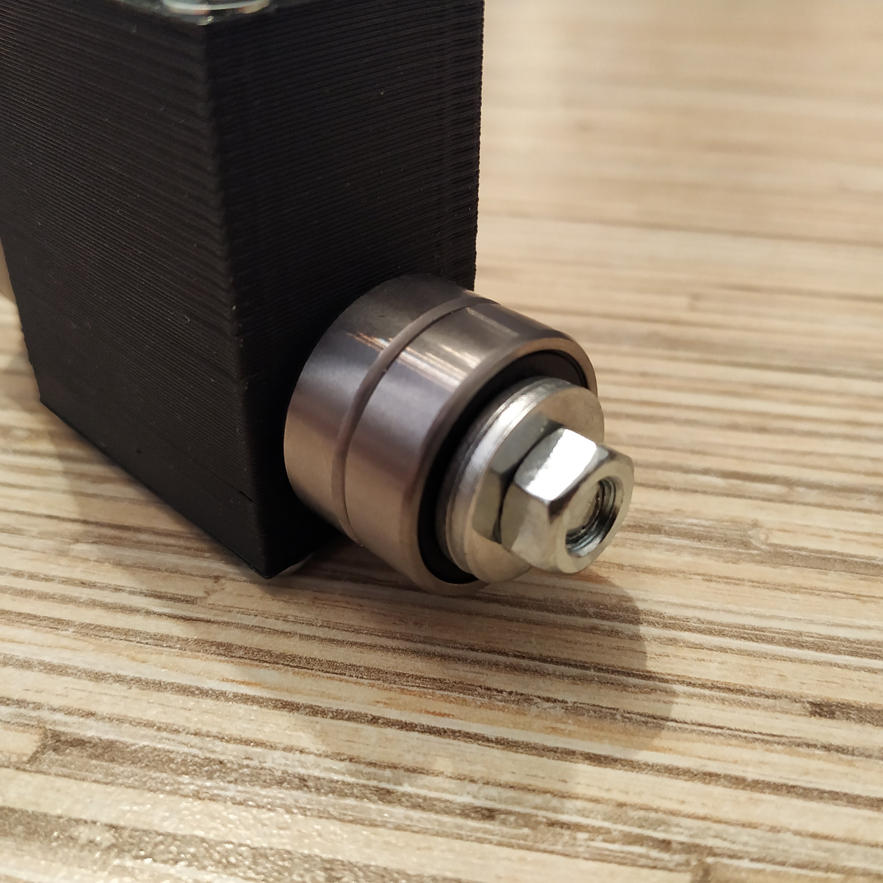
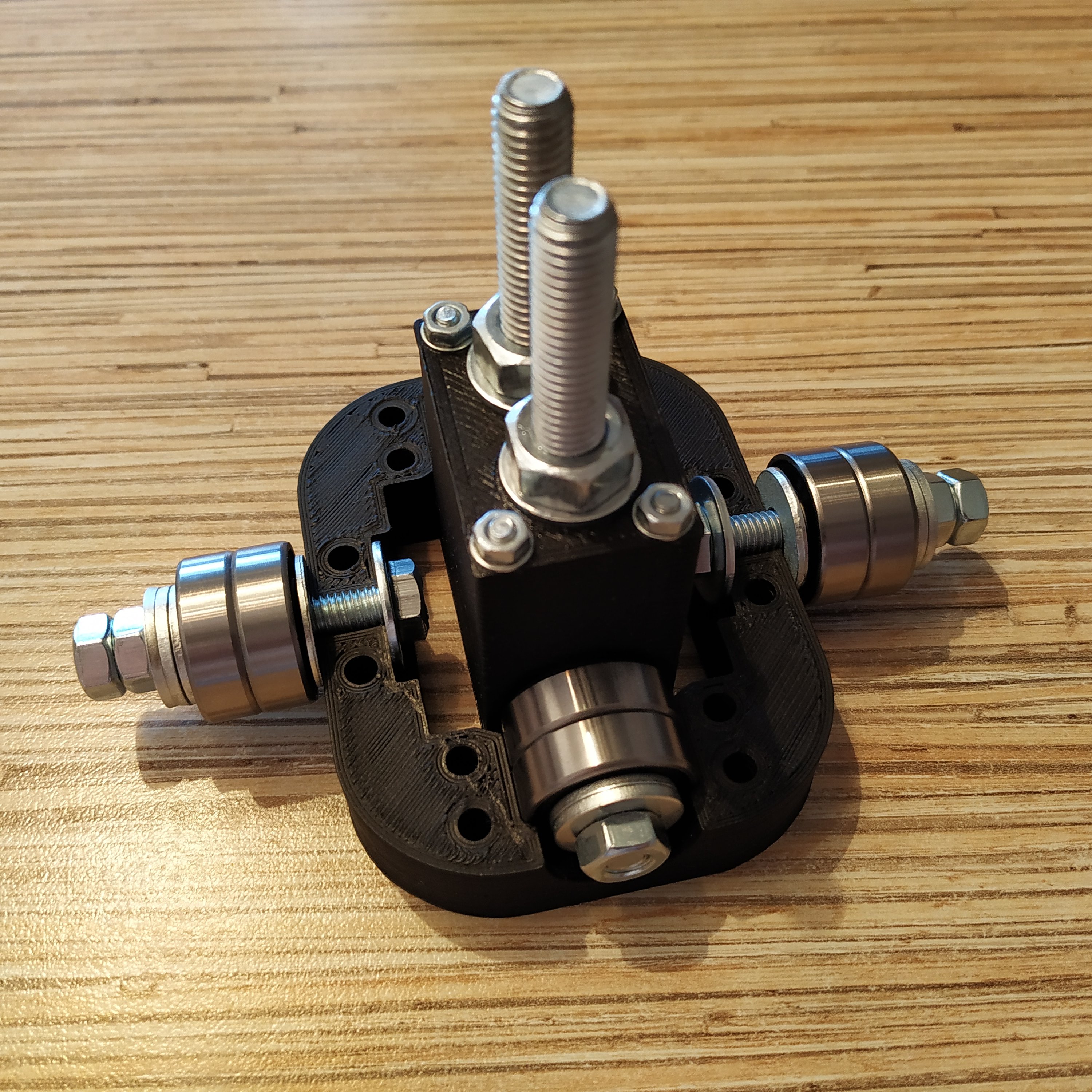
3. Take an M6x80mm bolt and put a 18x6x8mm cylinder onto it. Add 2 washers and 2 608ZZ bearings. Add a washer after bearings. Add another M8 nut after you'll put bearings on.
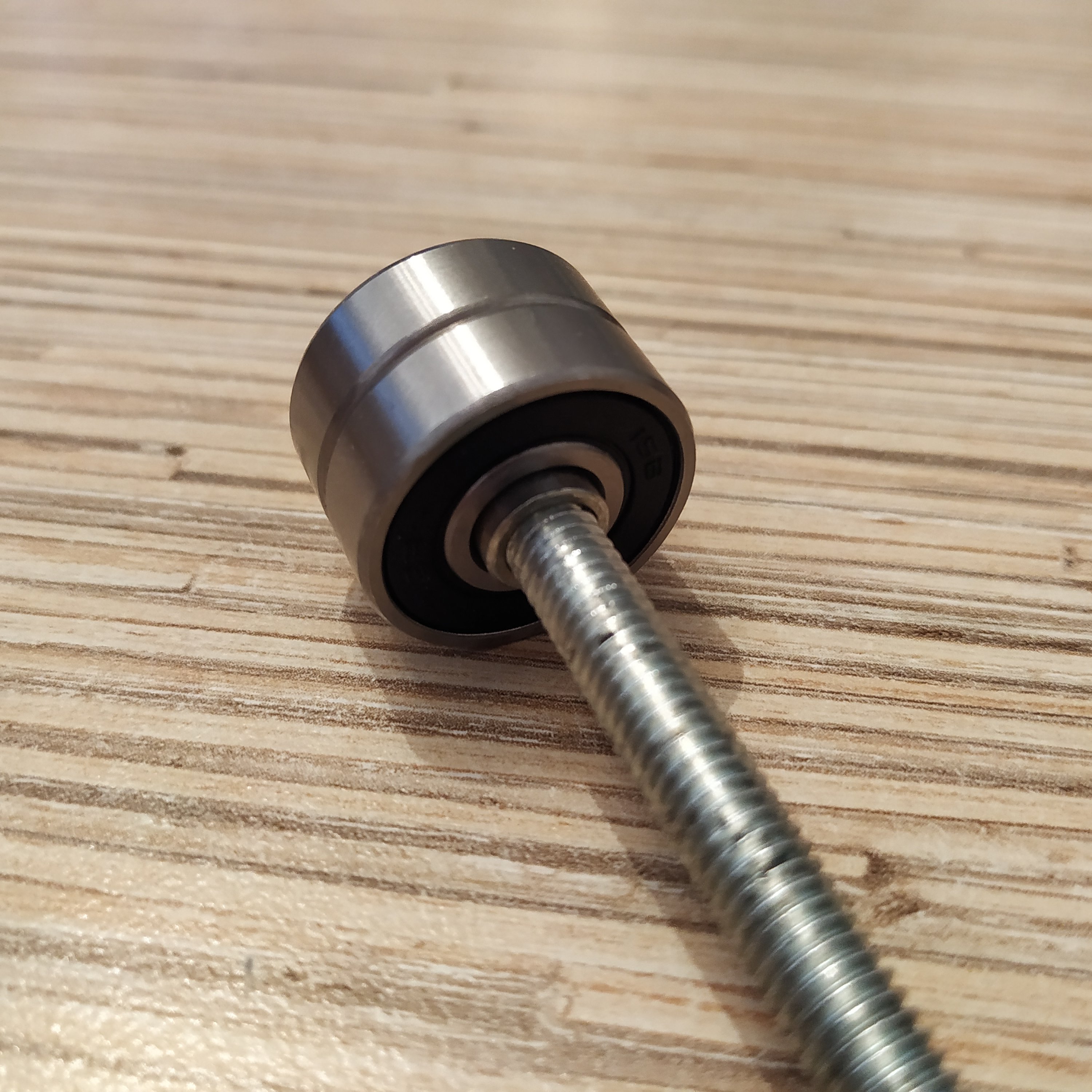
4. Press-fit 2x M6 washers into lever connector part
5. Insert the bolt with axis assembly into the lever connector part. Put another cylinder on, add an M8 washer, 2 bearings, 2 more M8 washers and a nut (use thread locker on the nut):


6. Press-fit the lever connector part with fitted X-axis into X-axis hinge
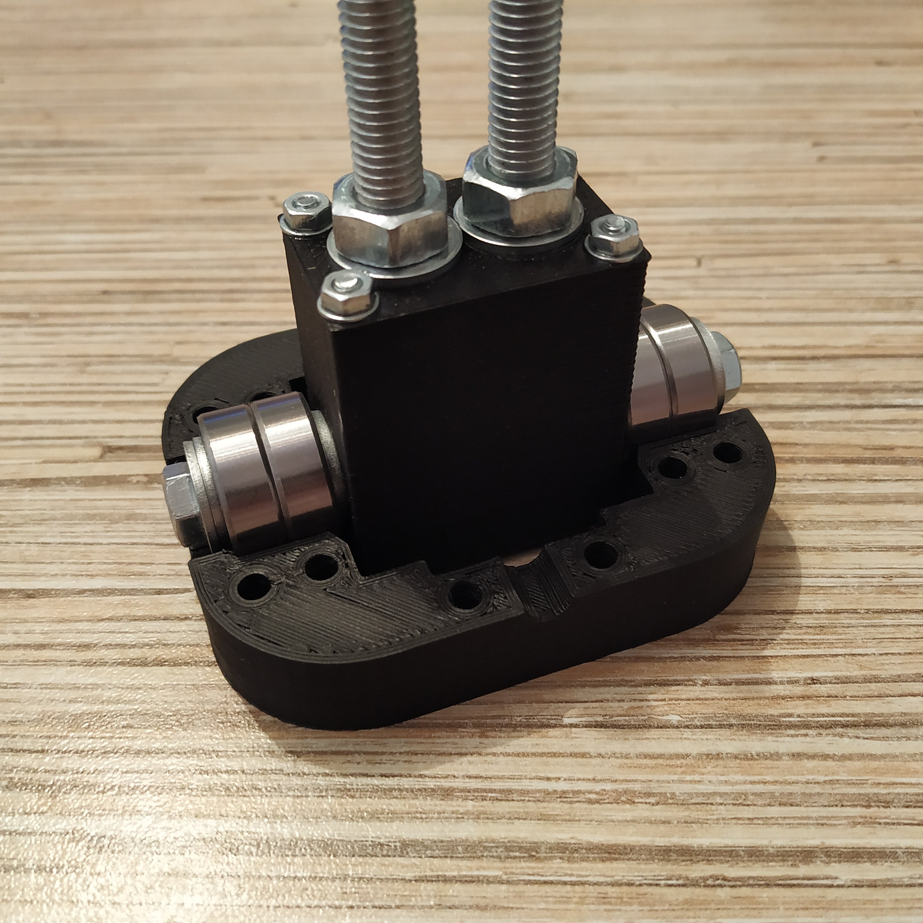
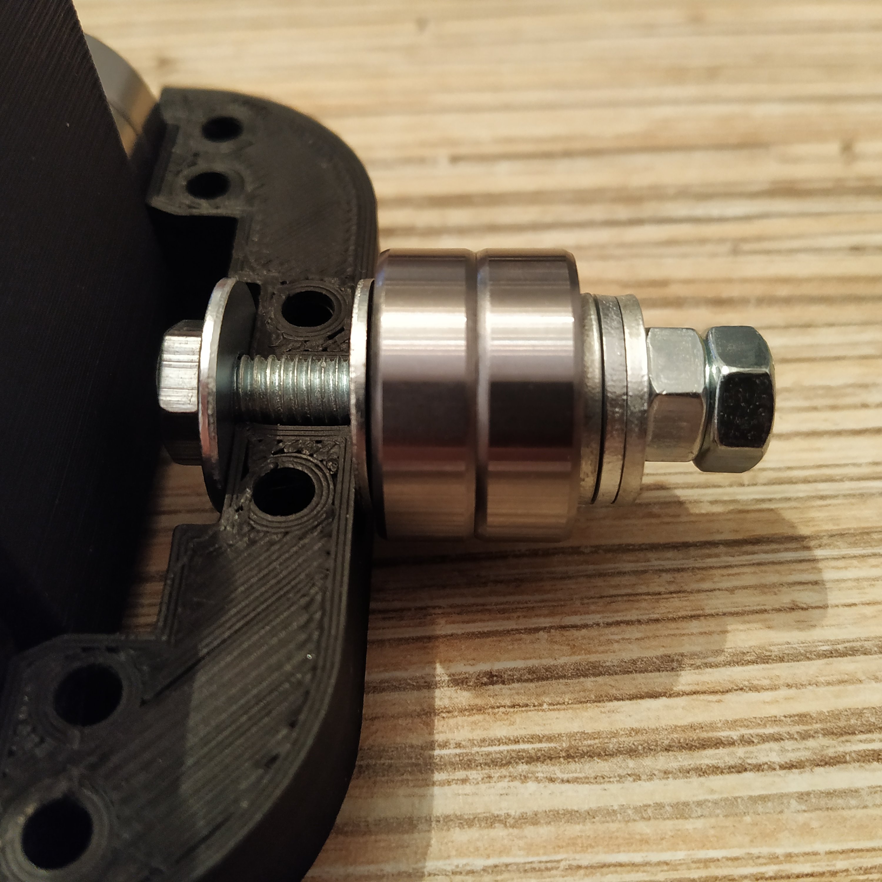
7. Take an M6x40mm bolt, fit a reinforced M6 washer onto it, then another one, the cylinder, 2 bearings,3 (4 on the magnet side) M8 washers, 2 M6 nuts and fit this axis assembly into the inner ring of the gimbal. Repeat the process for the second one. Do not tighten axes yet.
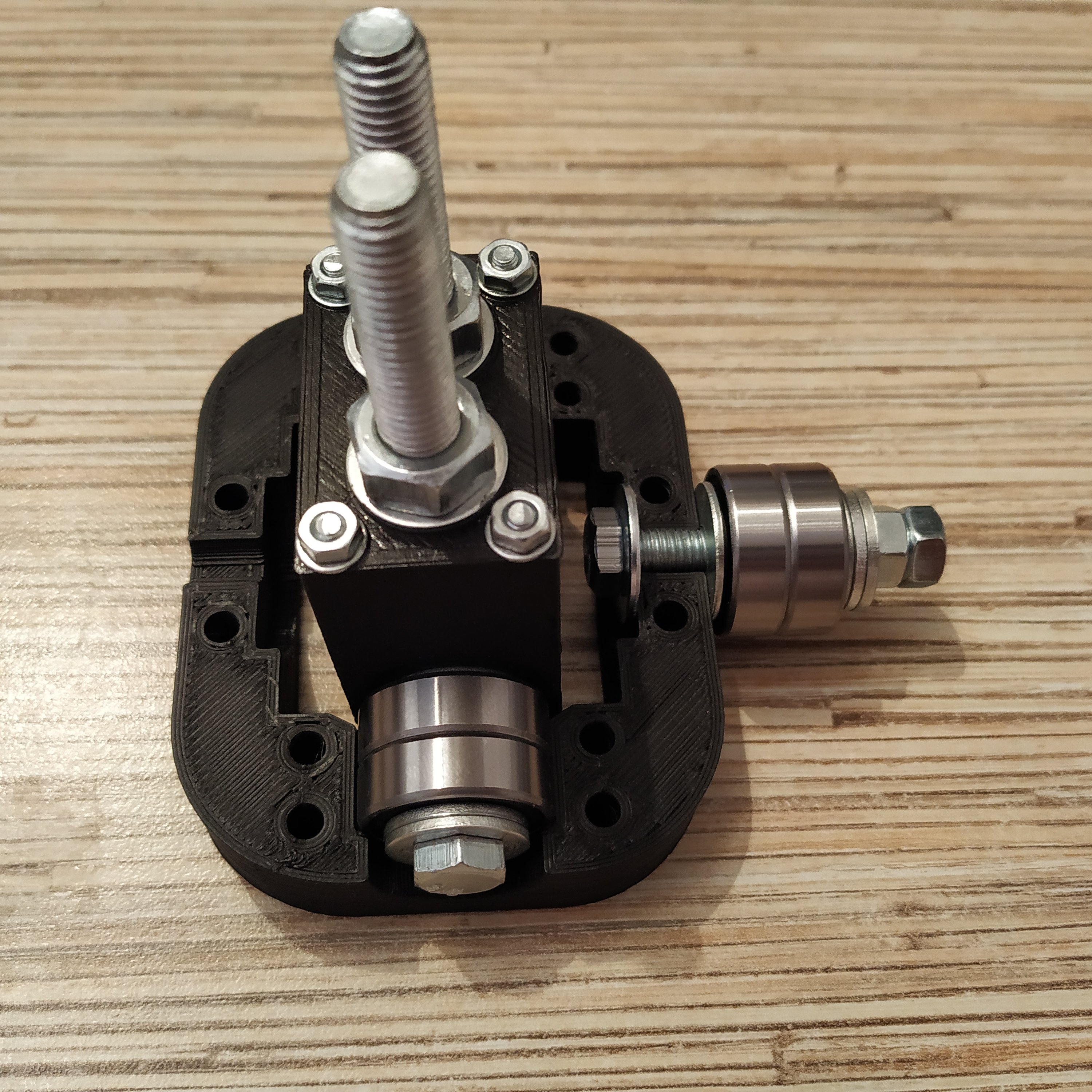
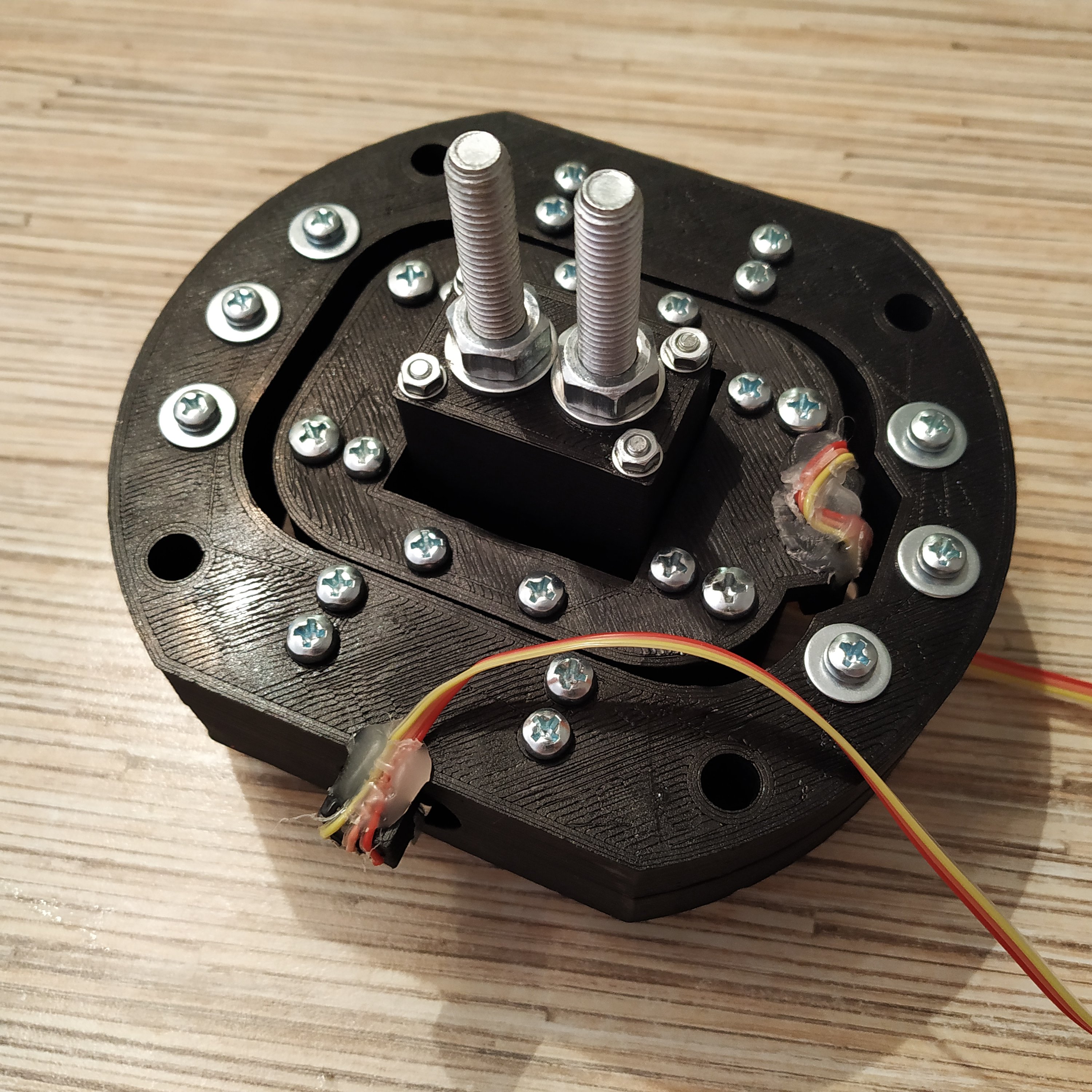
8. Attach the upper part of the inner ring. Fix it with 10 M4x40mm screws and 4 M4x50mm screws (use them at angles). Tighten axis bolts, use thread locker on M6 nuts (not on the cylinder!) and M4 ones. Use washers as shown in pictures below.
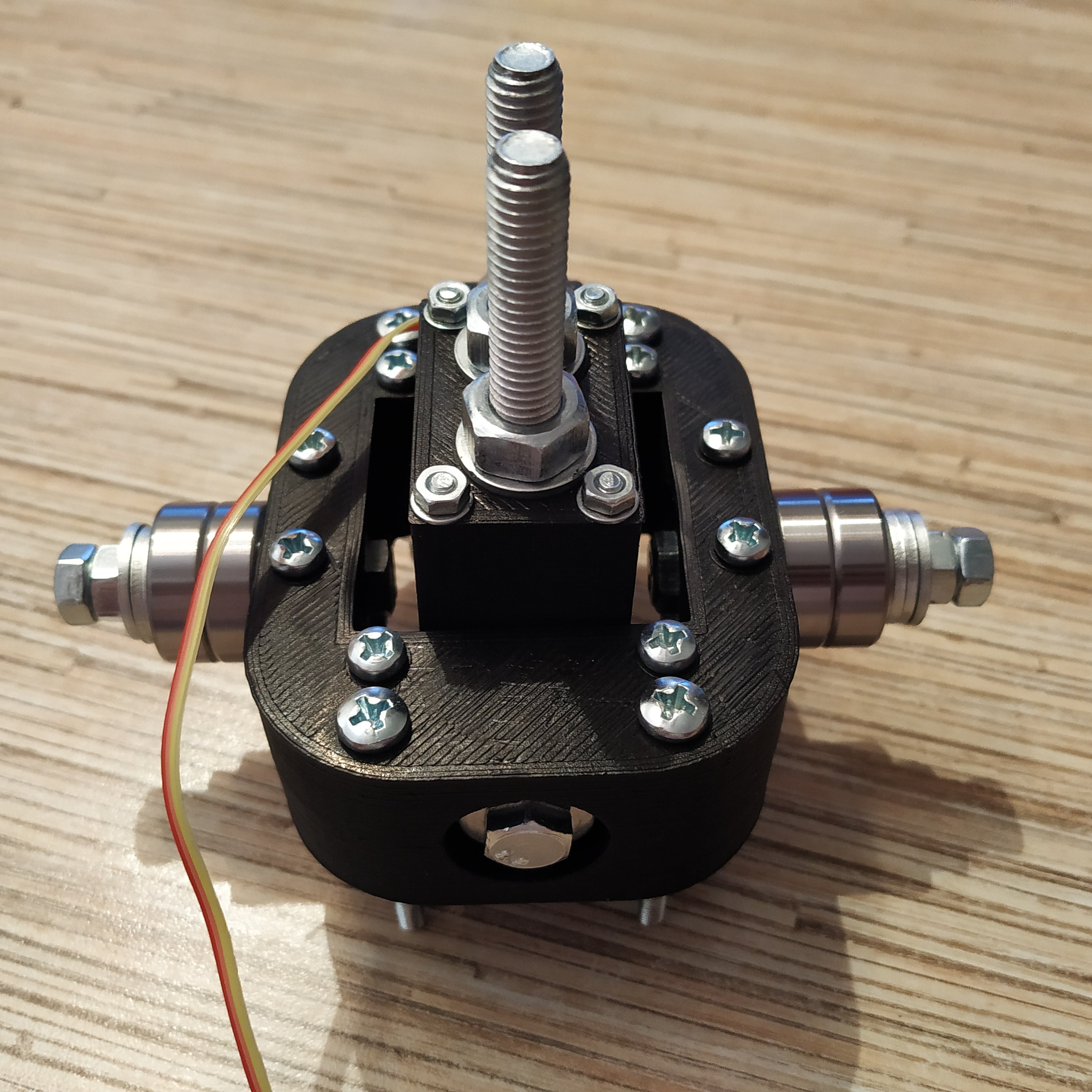
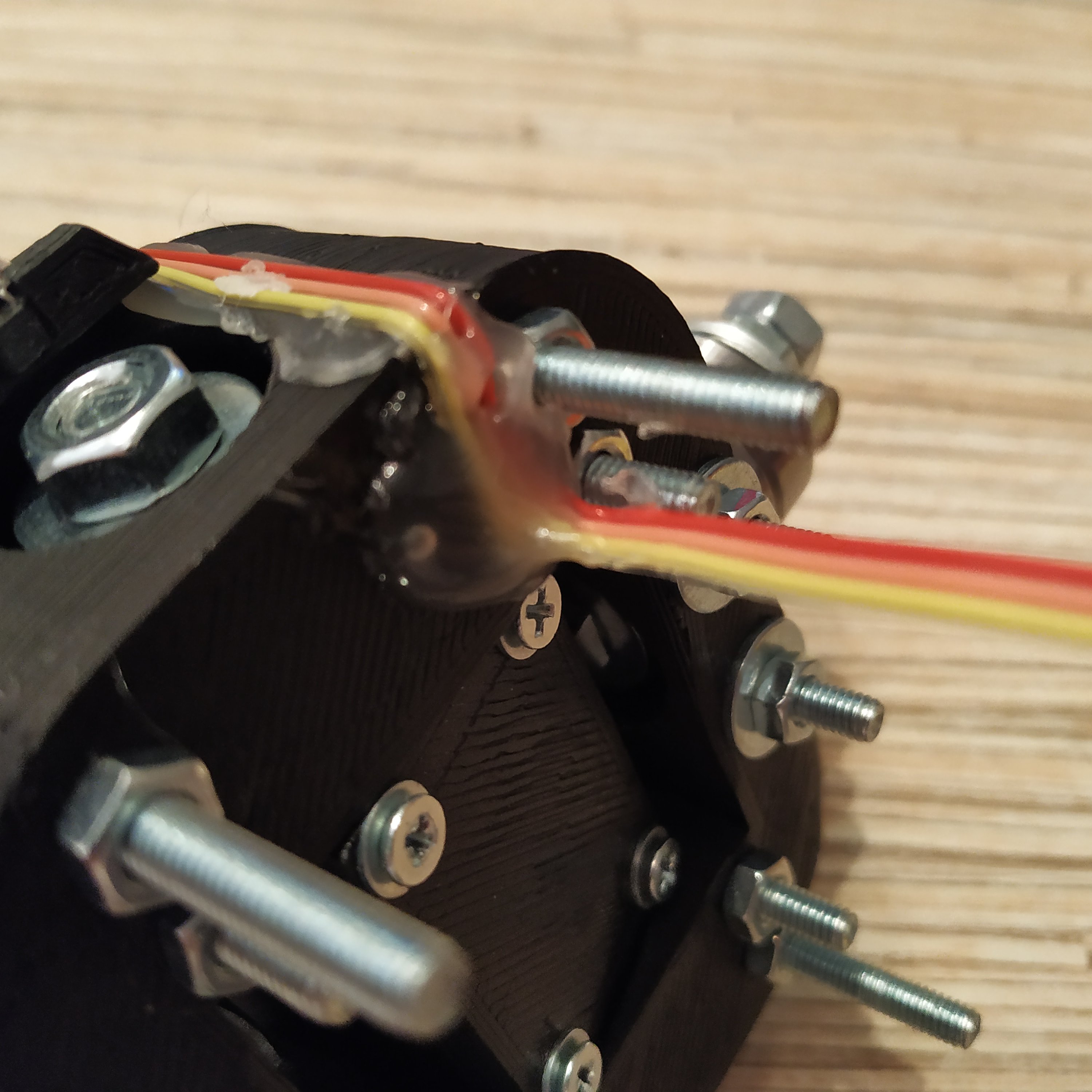
9. Time for some cable management! Glue the 3-wire sensor cable onto the side of the assembly with some hot glue.
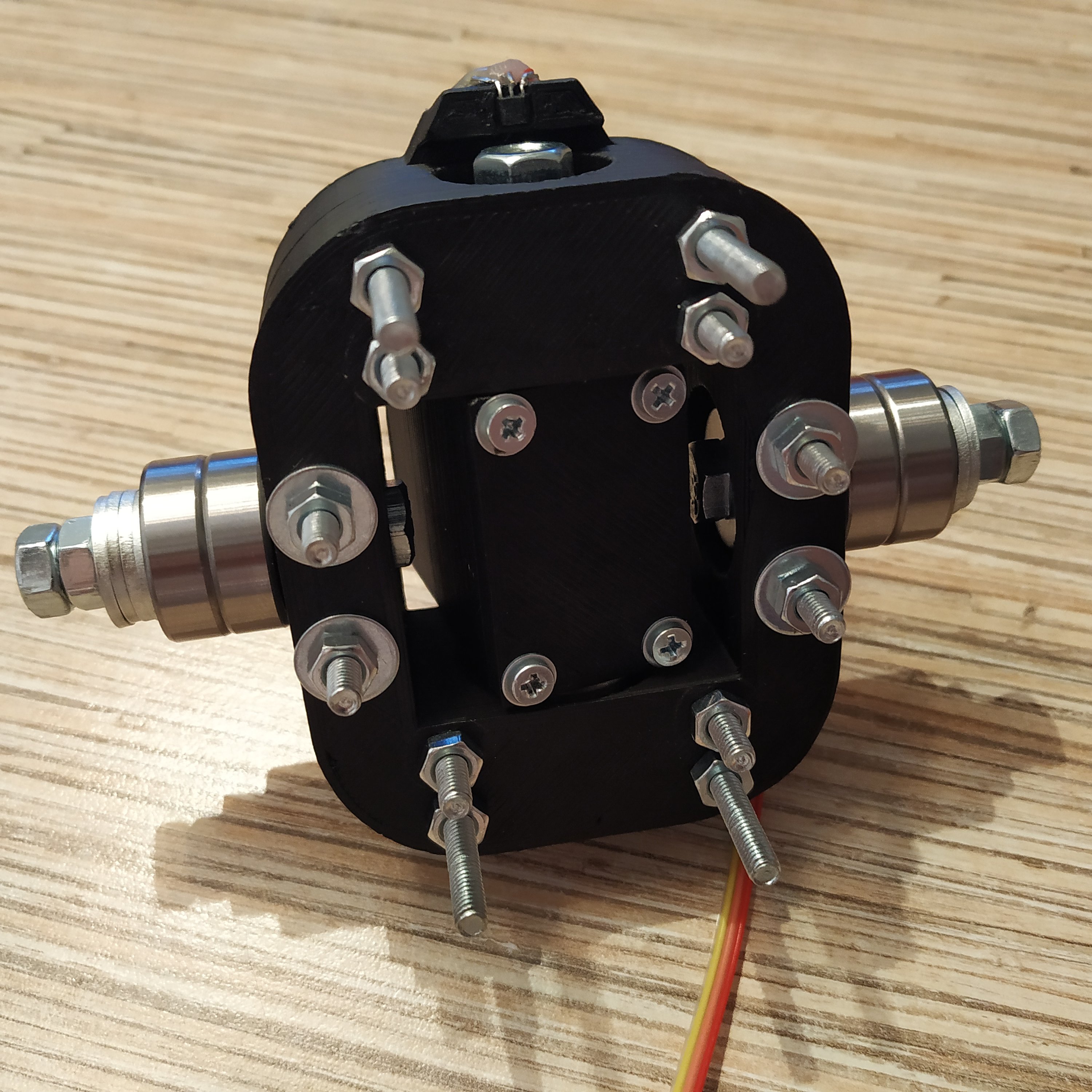
10. Put the assembly into the lower part of the outer ring. Put the upper part of the outer ring onto the assembly and fix it with 14 M4x40mm screws. Use washers on both sides of some bolts as shown in pictures below.
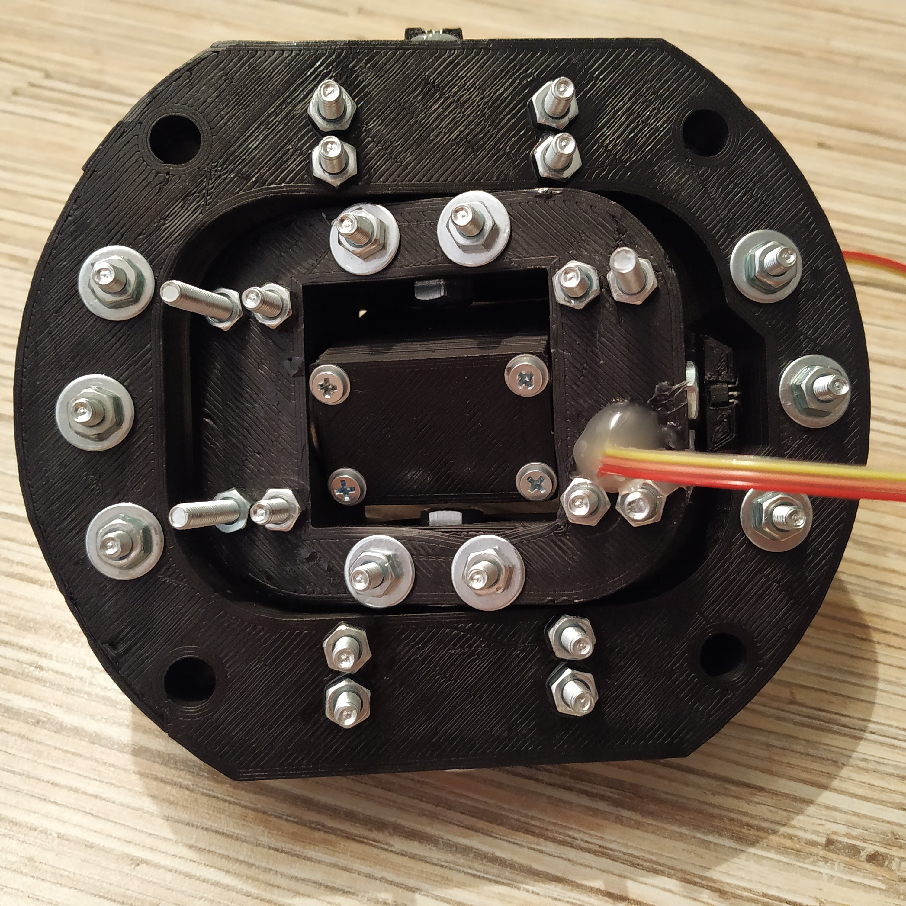
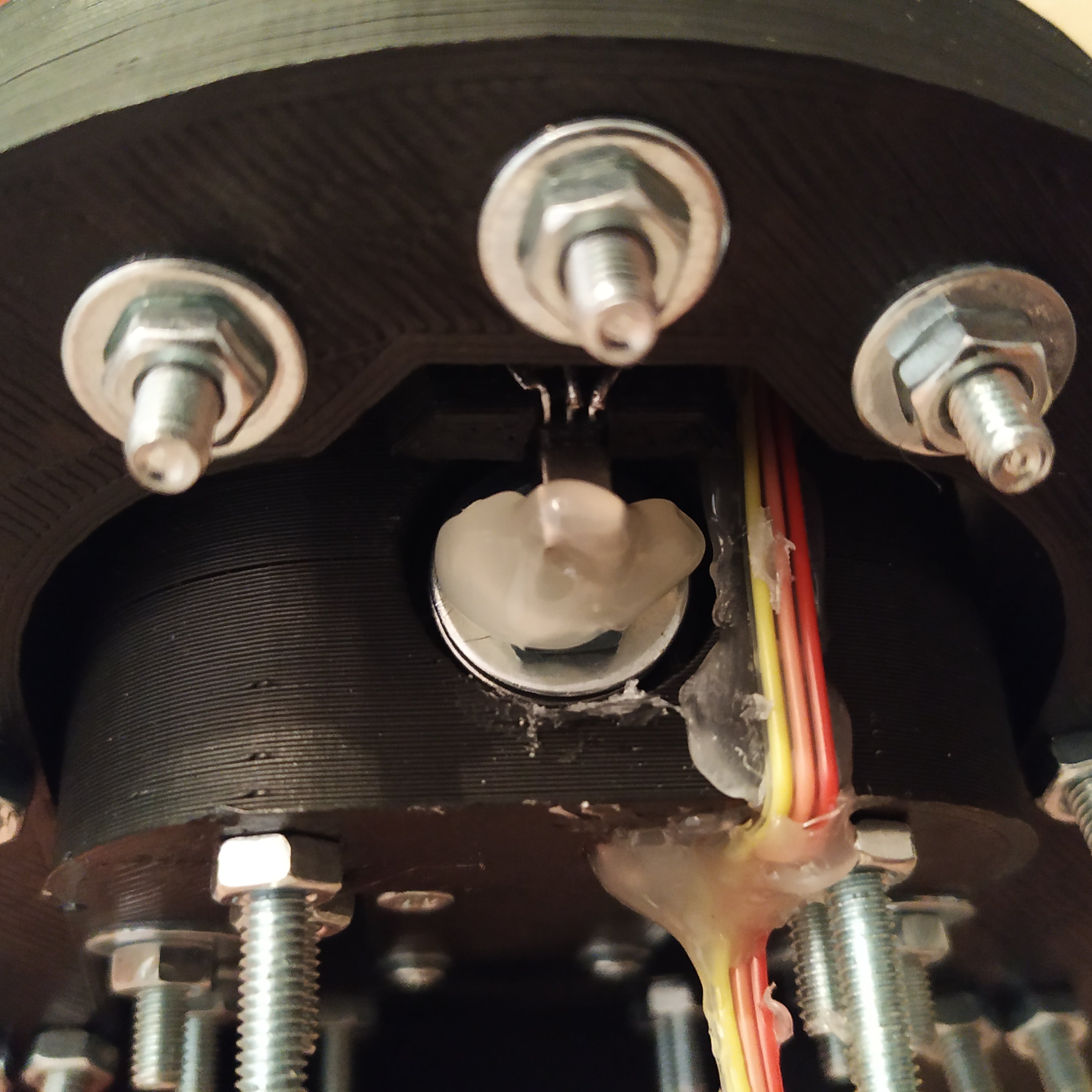
11. Do some cable management and glue the Y-axis sensor cable to the side of the outer ring.

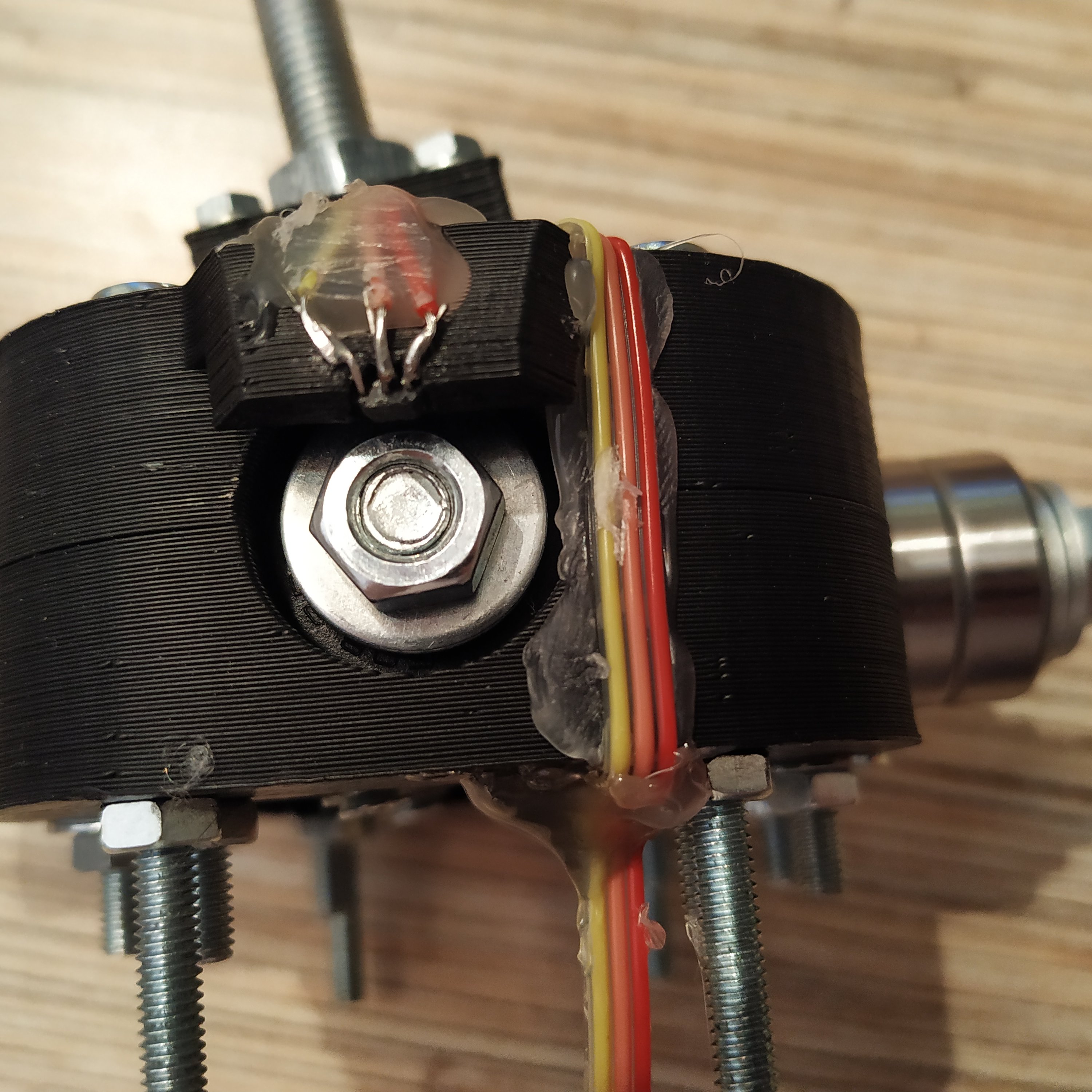
12. Put axis magnets onto nuts, make sure they are centered, use hot glue to fix them in place.Don't worry about centering axes too much, we'll do it later during the calibration process.

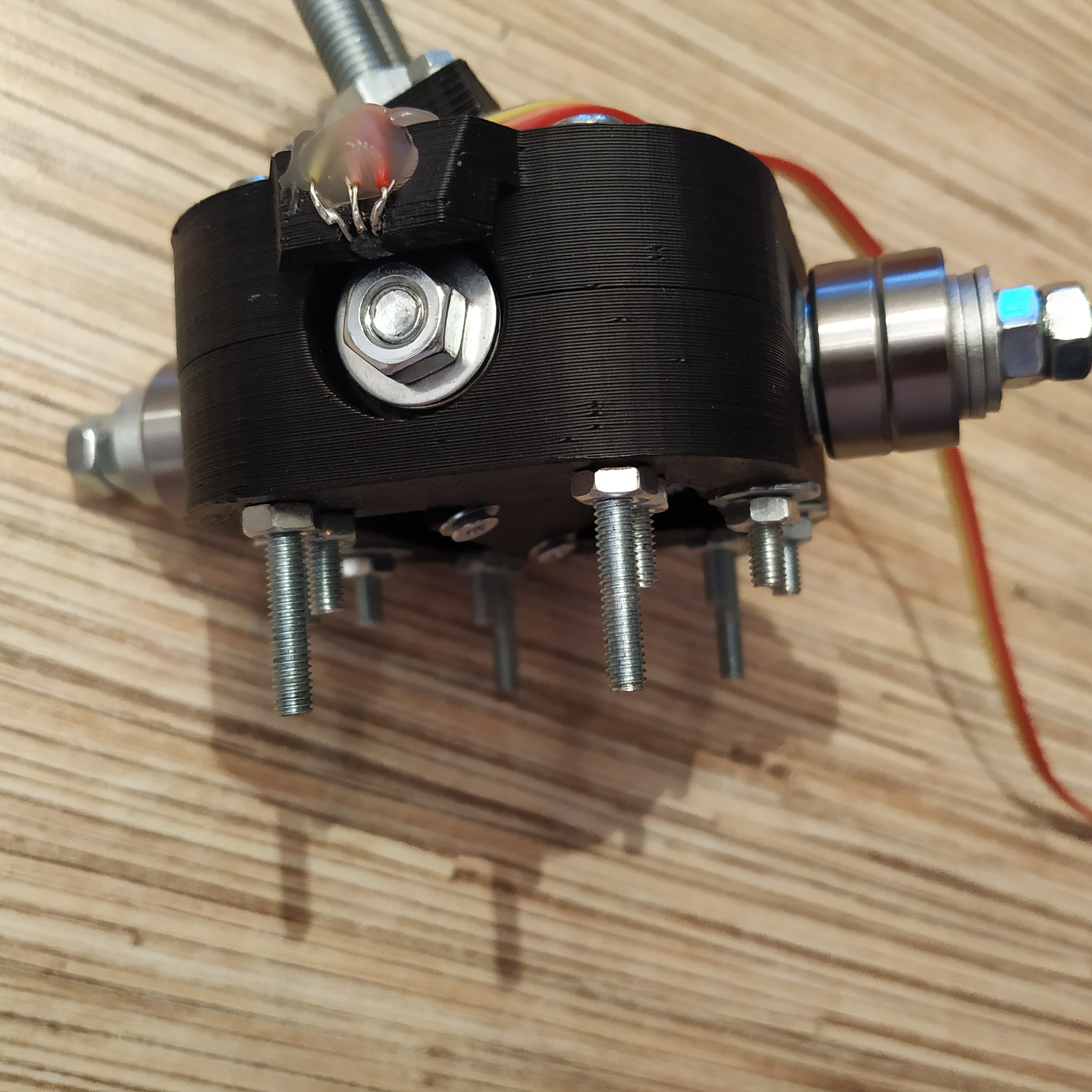
We are almost there. The gimbal rings assembly is finished:
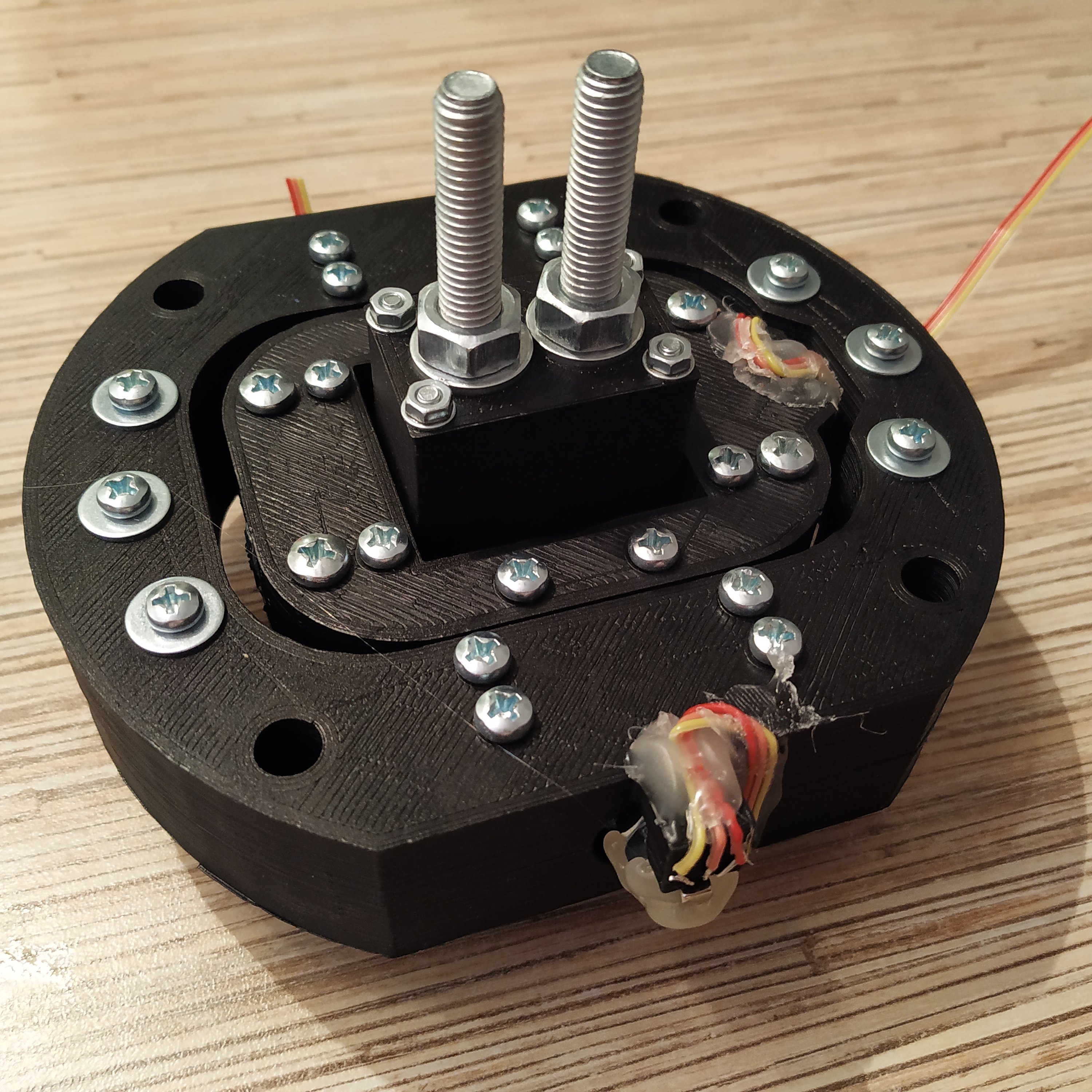
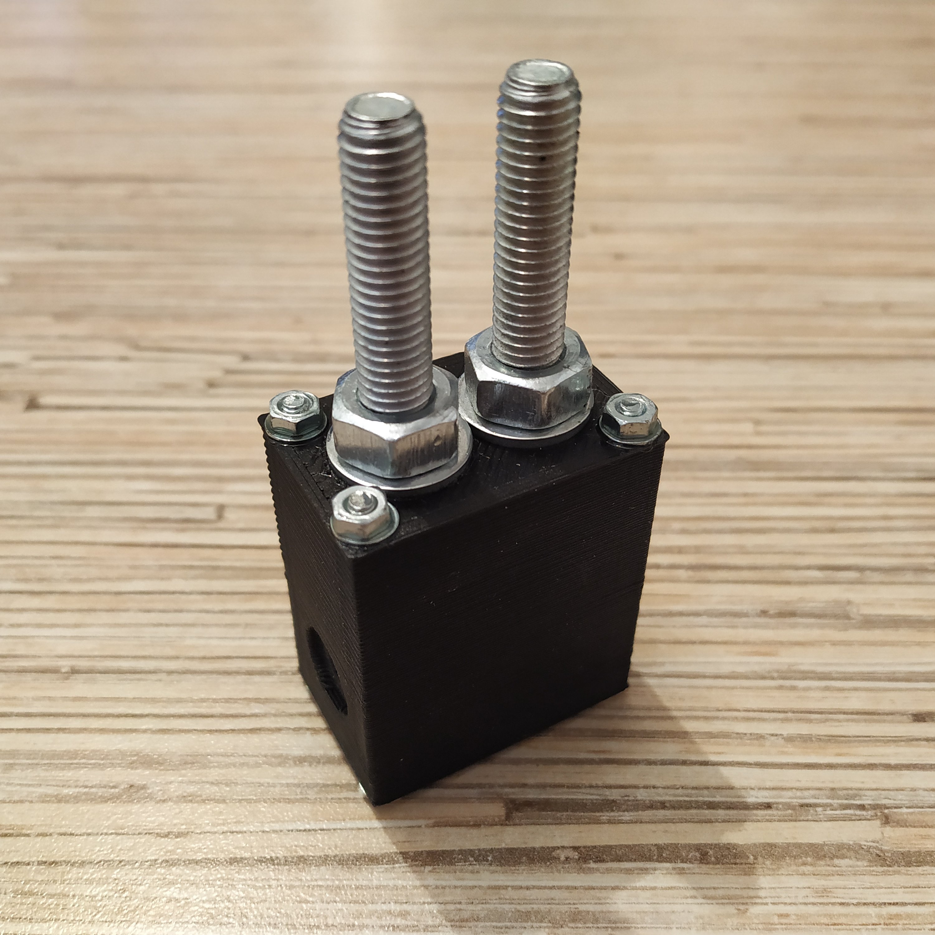
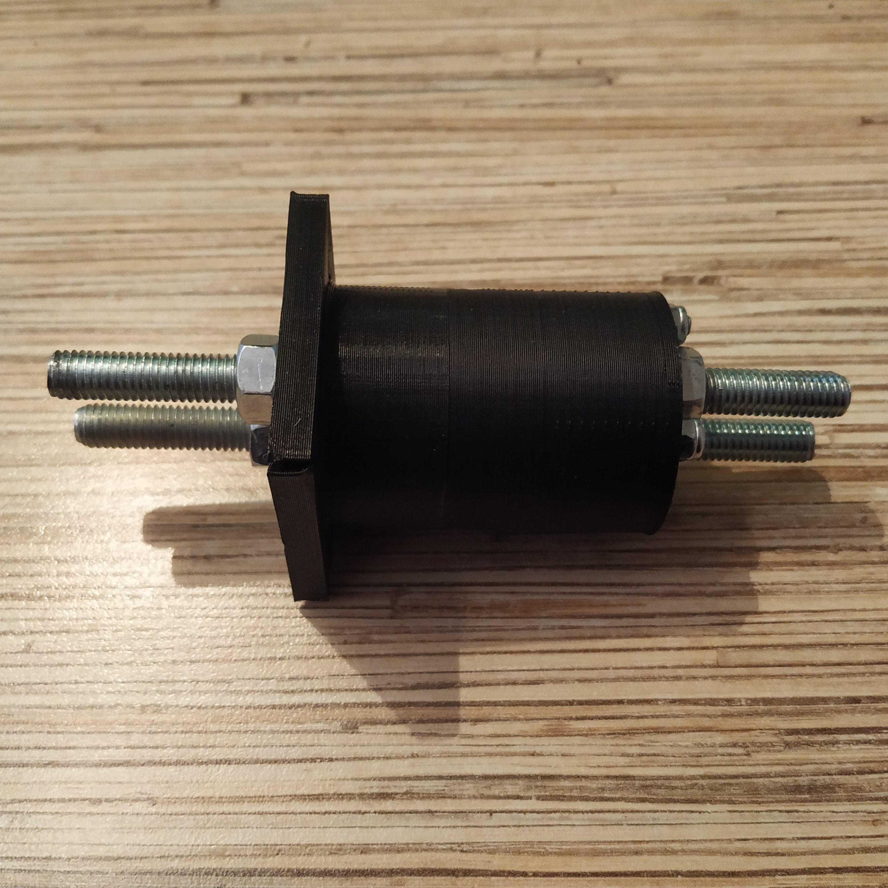
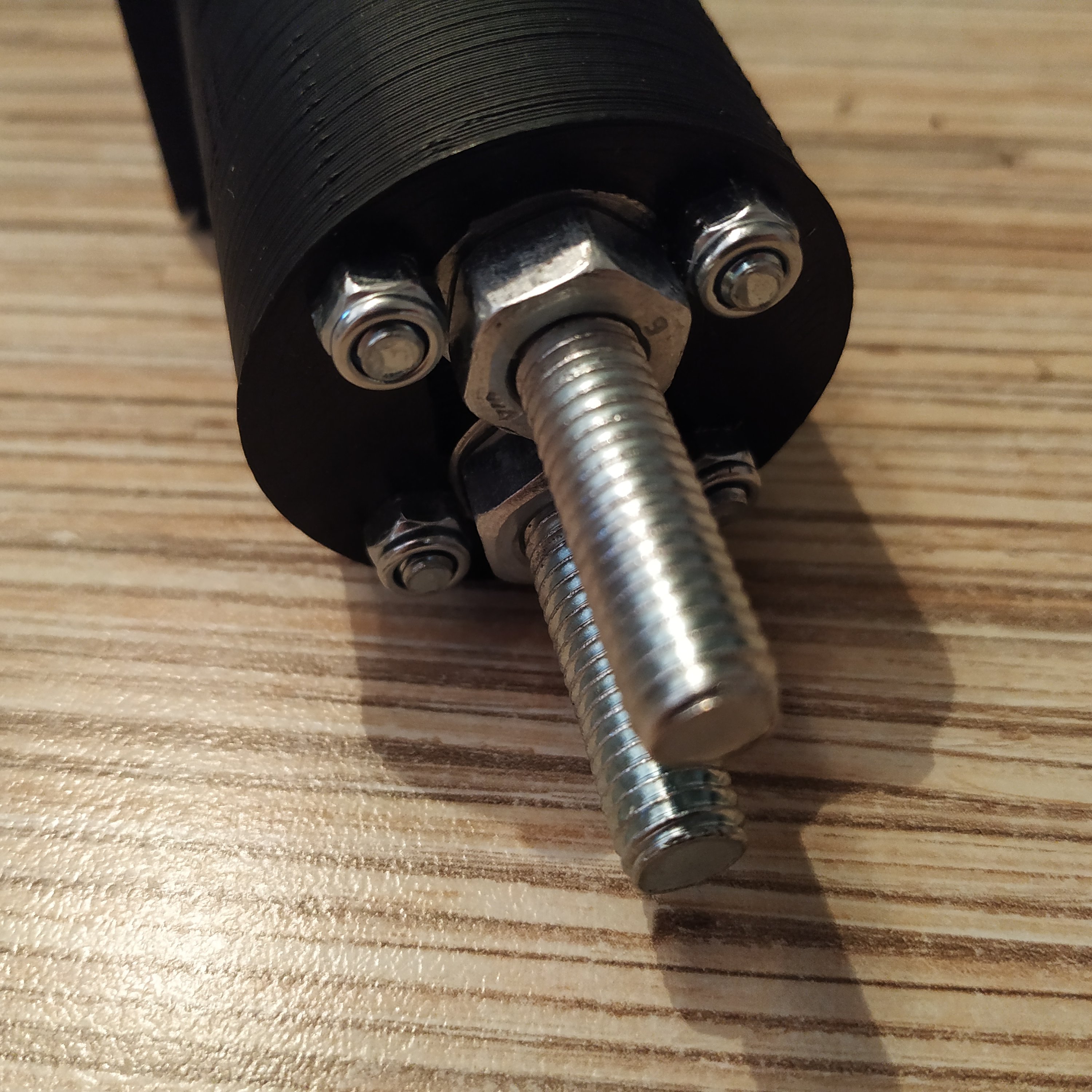
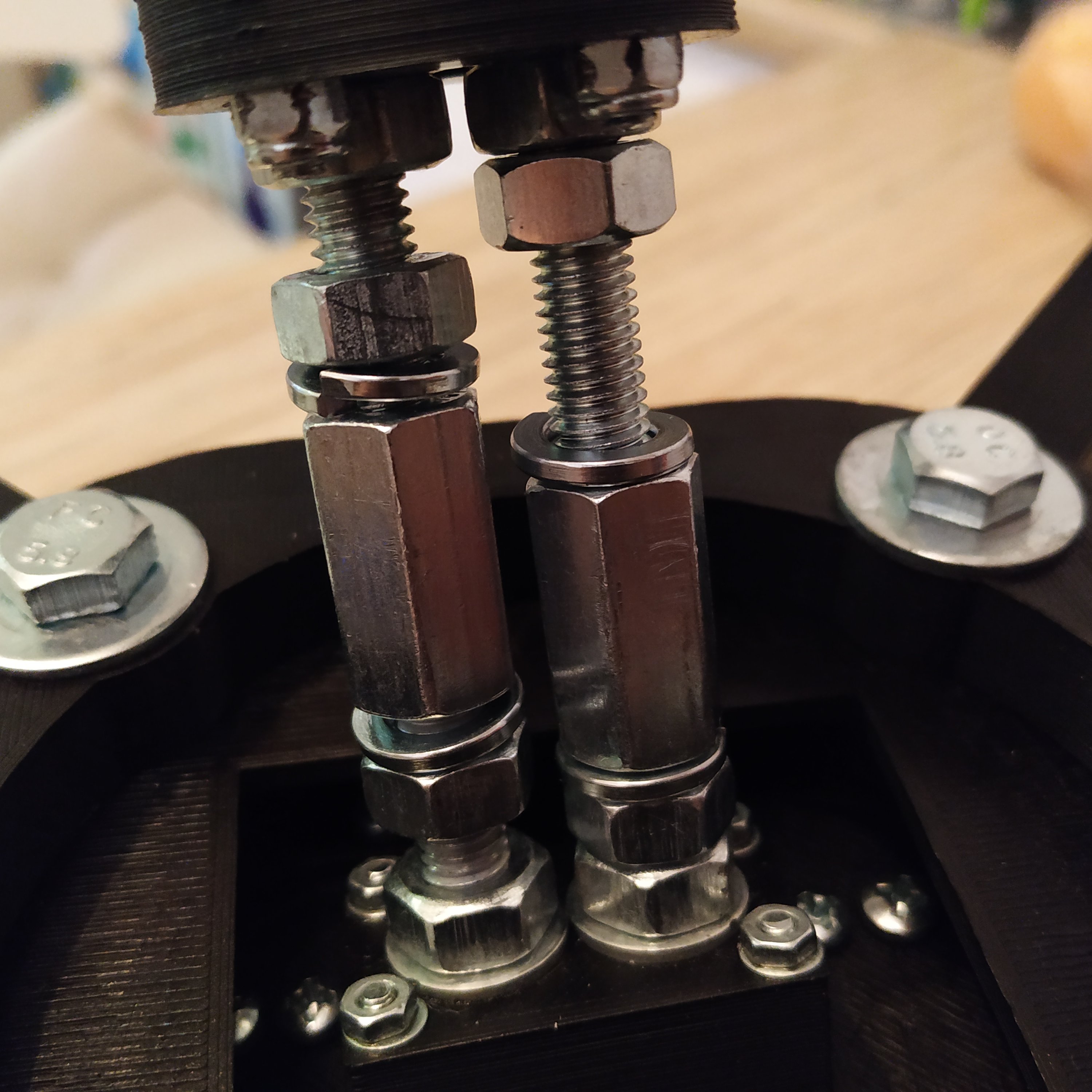
13. Press-fit 2 M8x50mm hex bolts into lever connector part 3. Put 2 washers and nuts on. Use thread locker.
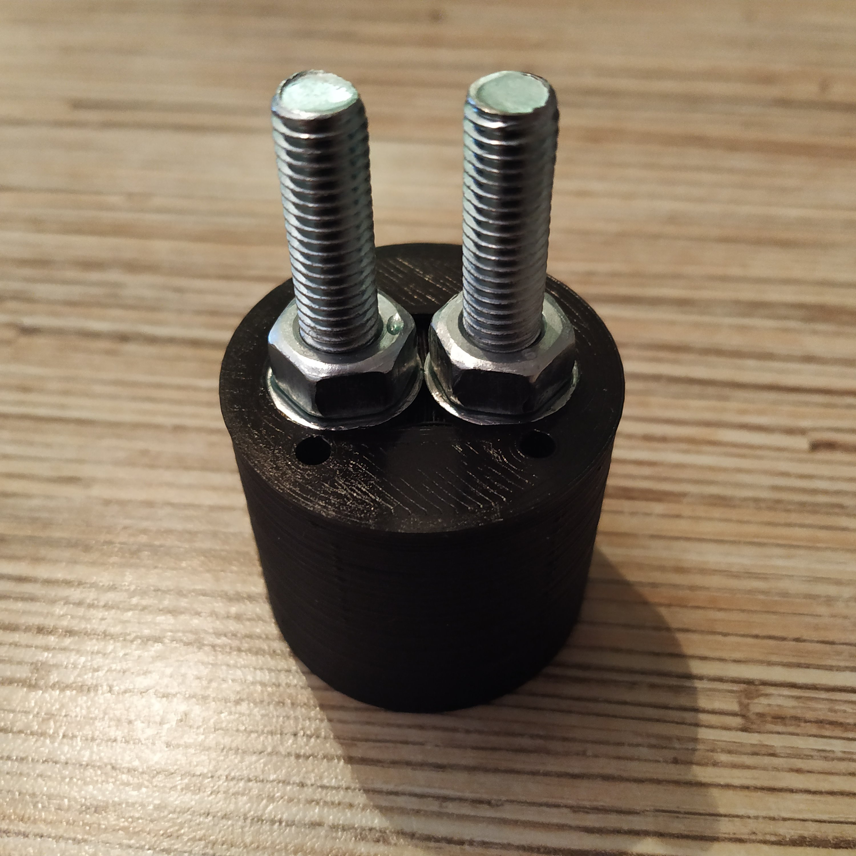
14.Press fit 2 M8x60mm hex bolts into lever connector part 4. Remove nuts from the part, connect parts 3 and 4, fix with M4x60mm screws and nuts. Put nuts back to lever connector part 4 bolts, use thread locker and tighten them firmly.

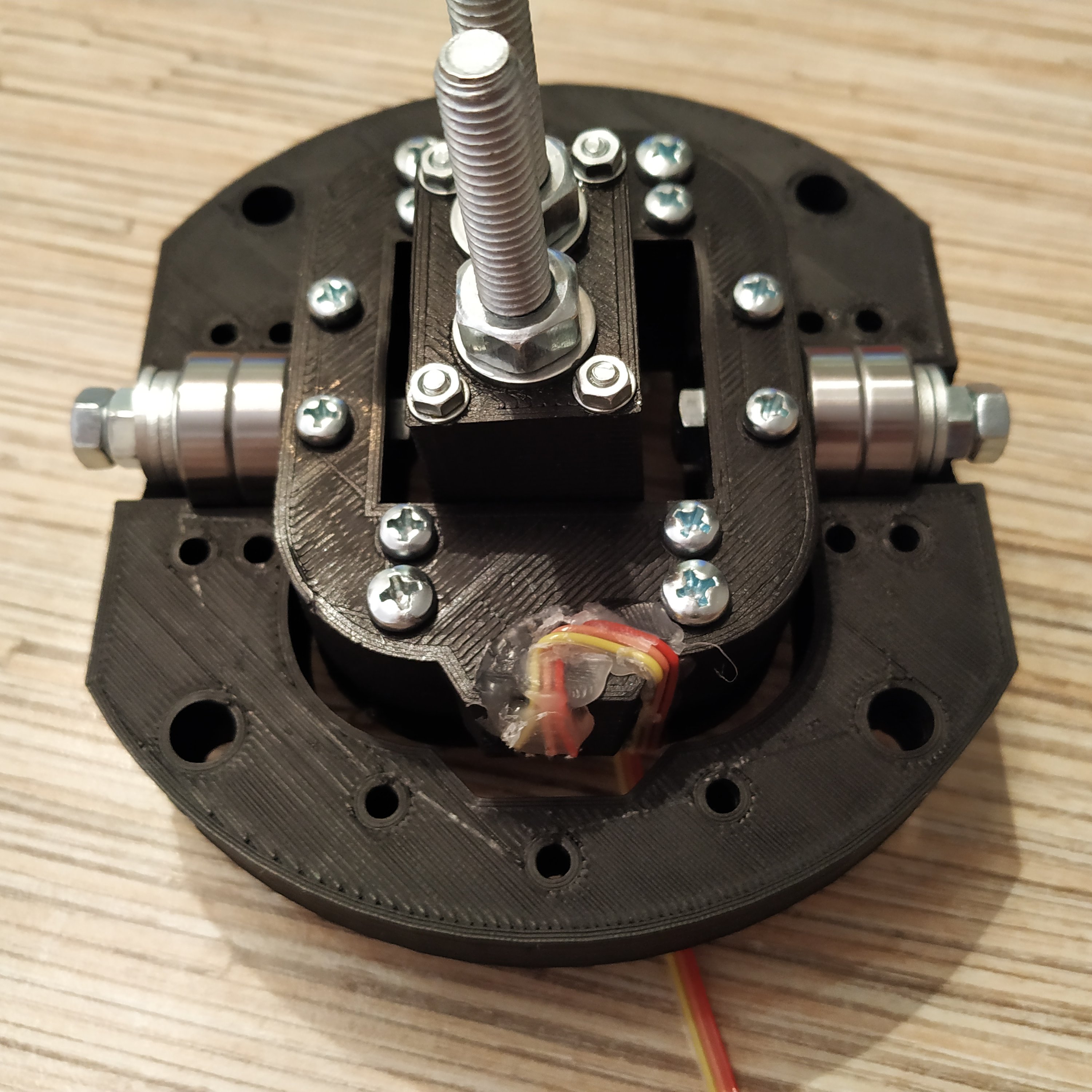
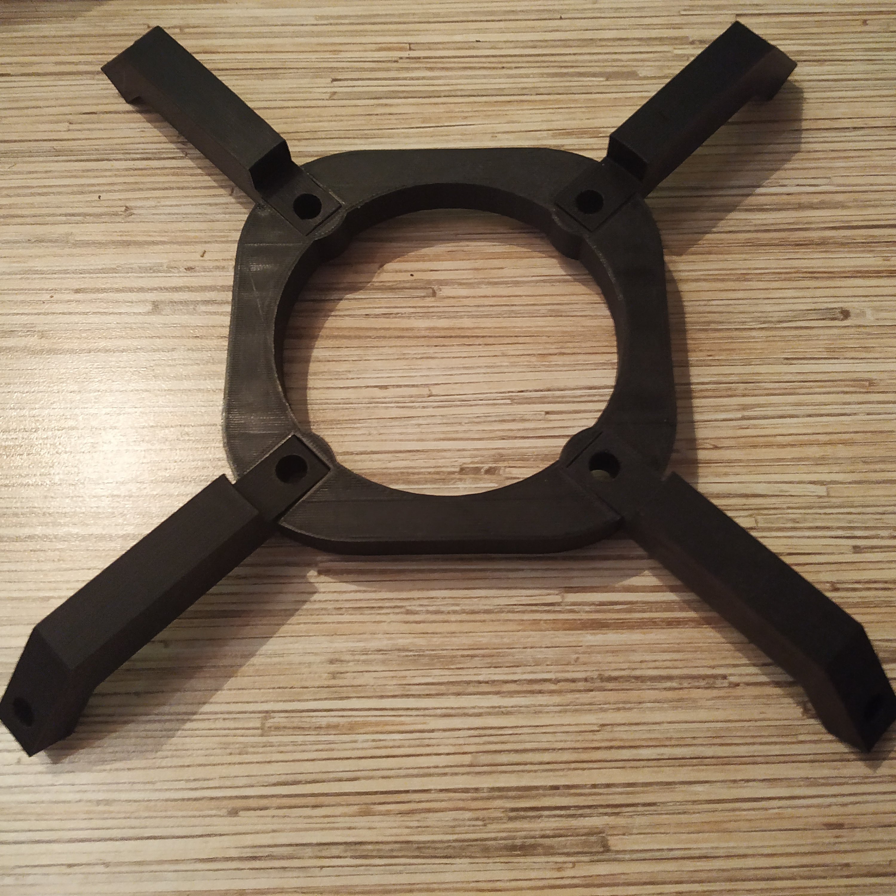
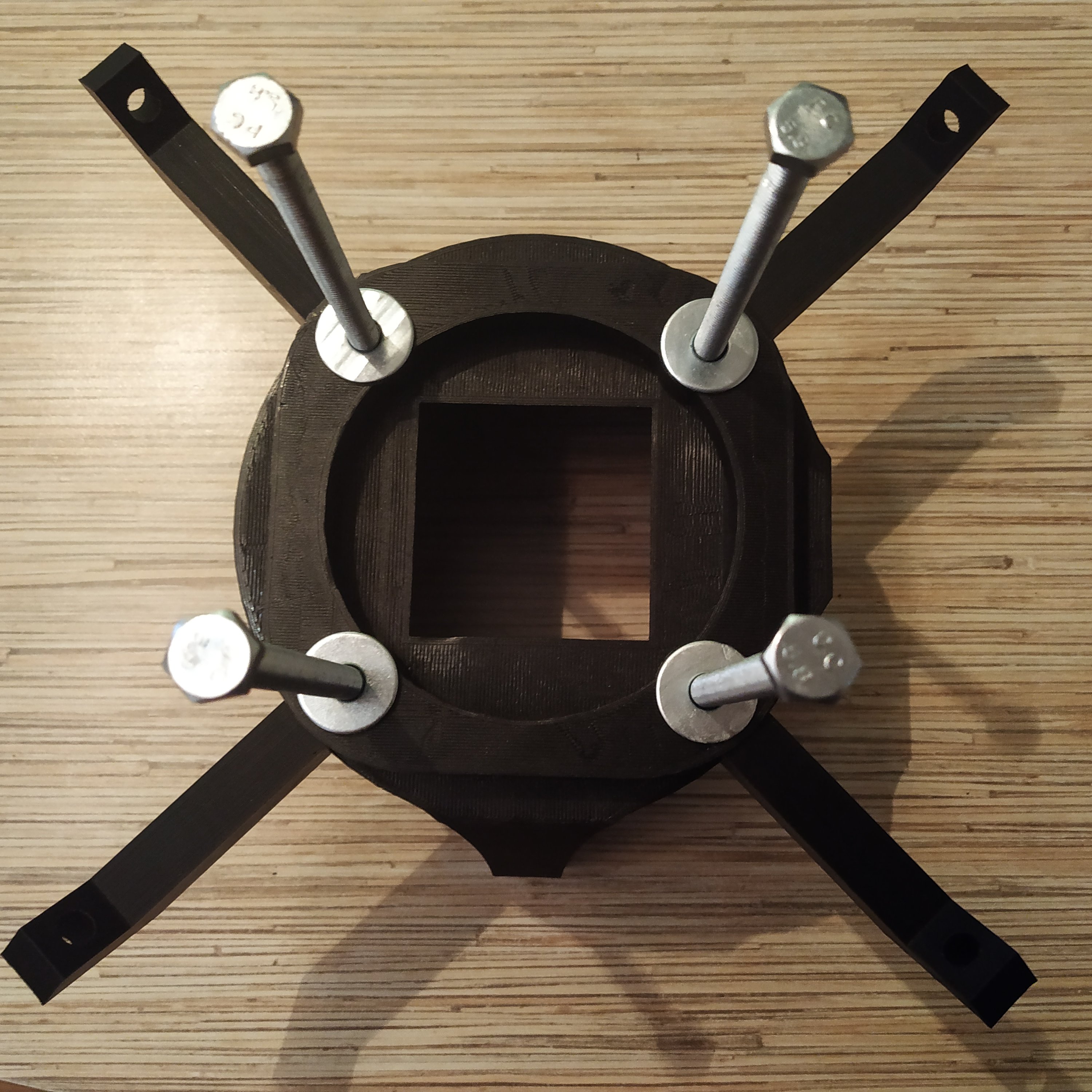
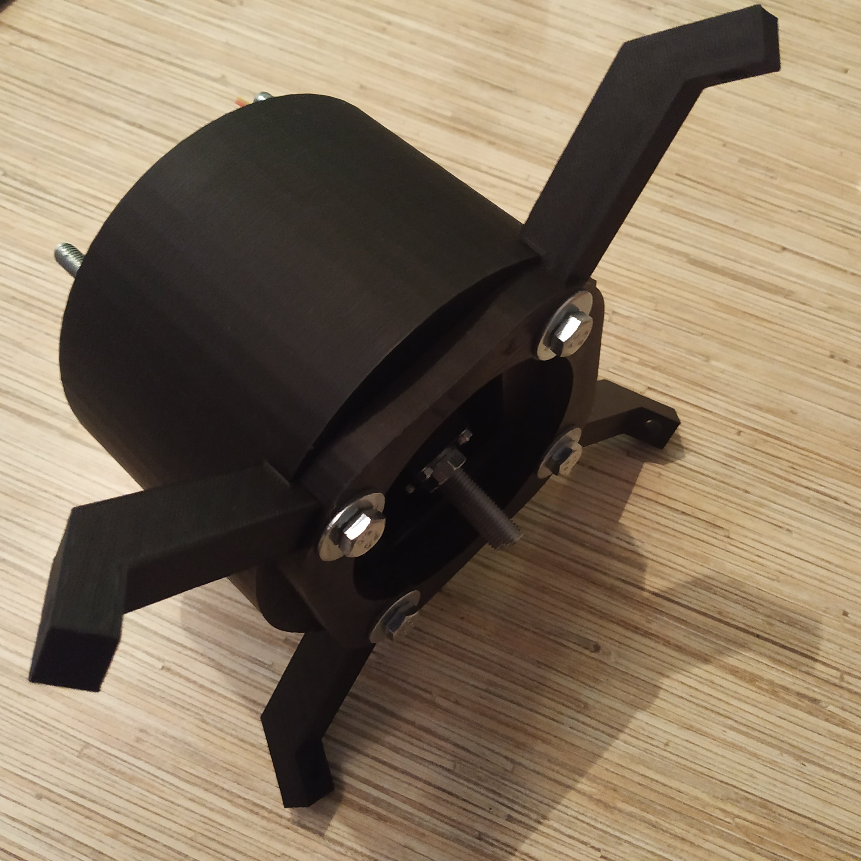
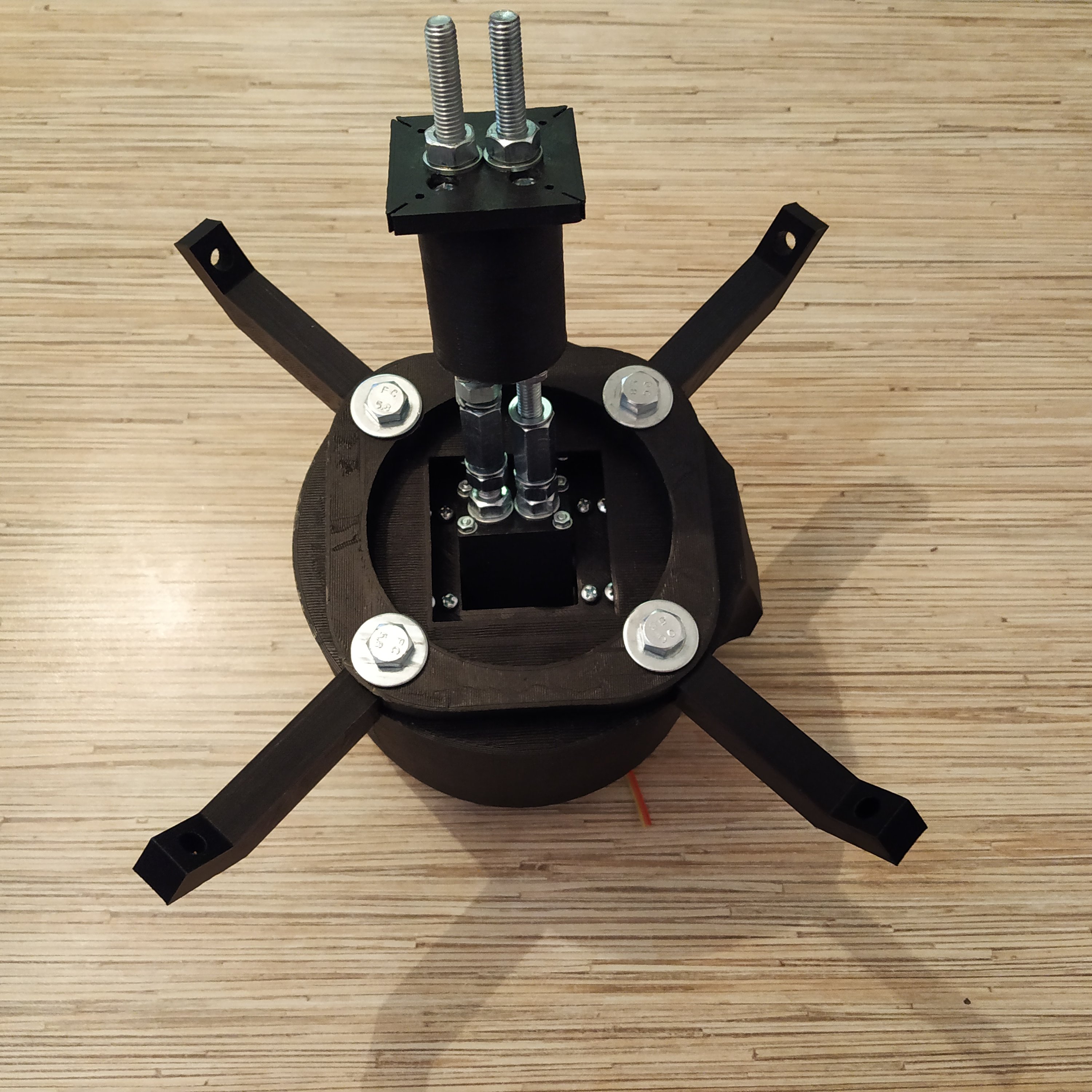
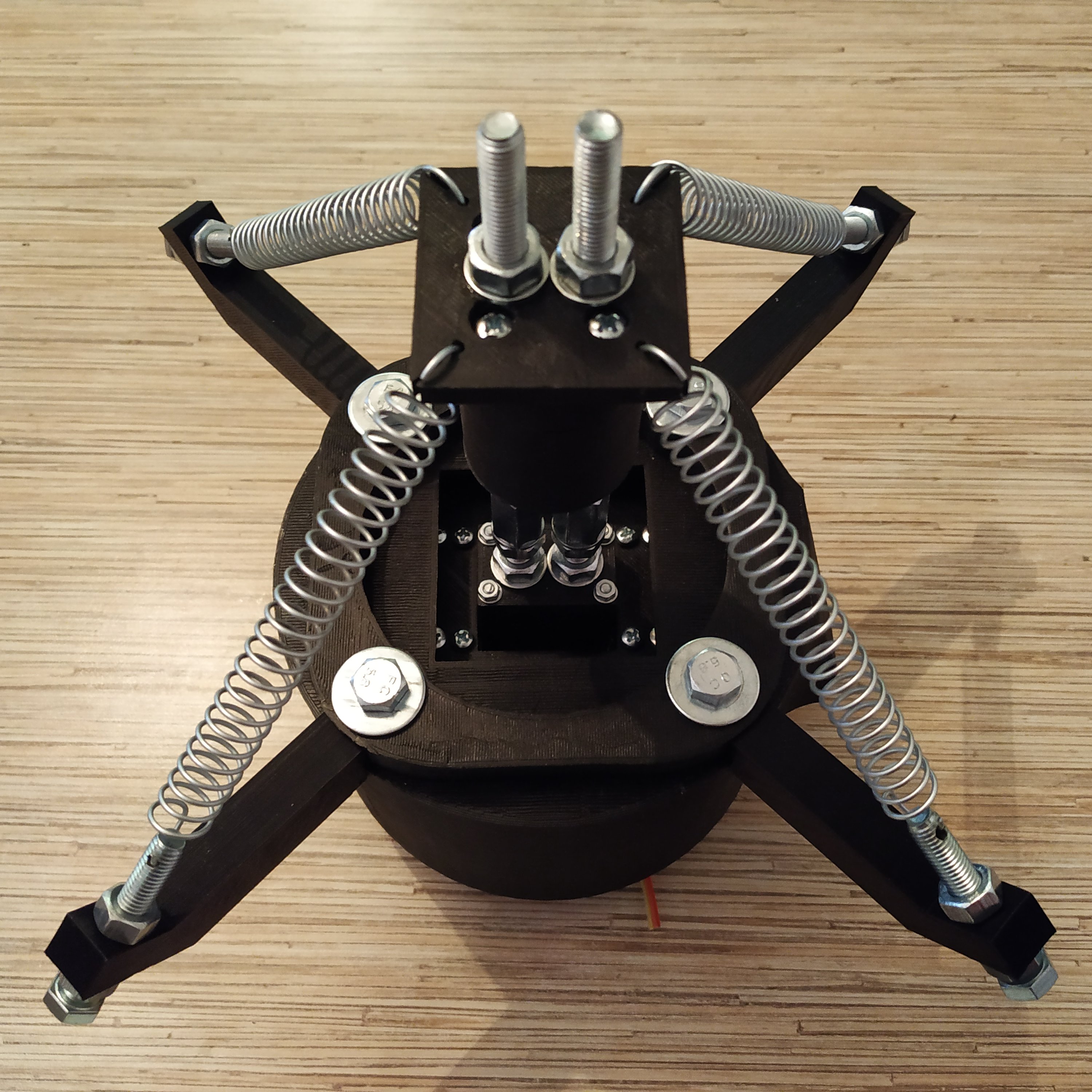
15. Put the spring holder assembly together, put it onto the box. Put gimbal rings assembly into the box and fix everything together with M8x140mm bolts. Put a washer, a spring washer and a nut on each bolt.

16. Attach the lever connector p3 and 4 assembly to the base. To do it, screw a nut, a spring washer, and a connector nut onto a bolt of the base, then put a nut and a washer onto 2 bottom bolts of the lever connector assembly. Connect them together as shown on the picture below, center the connector nut and fix it with nuts from both sides.

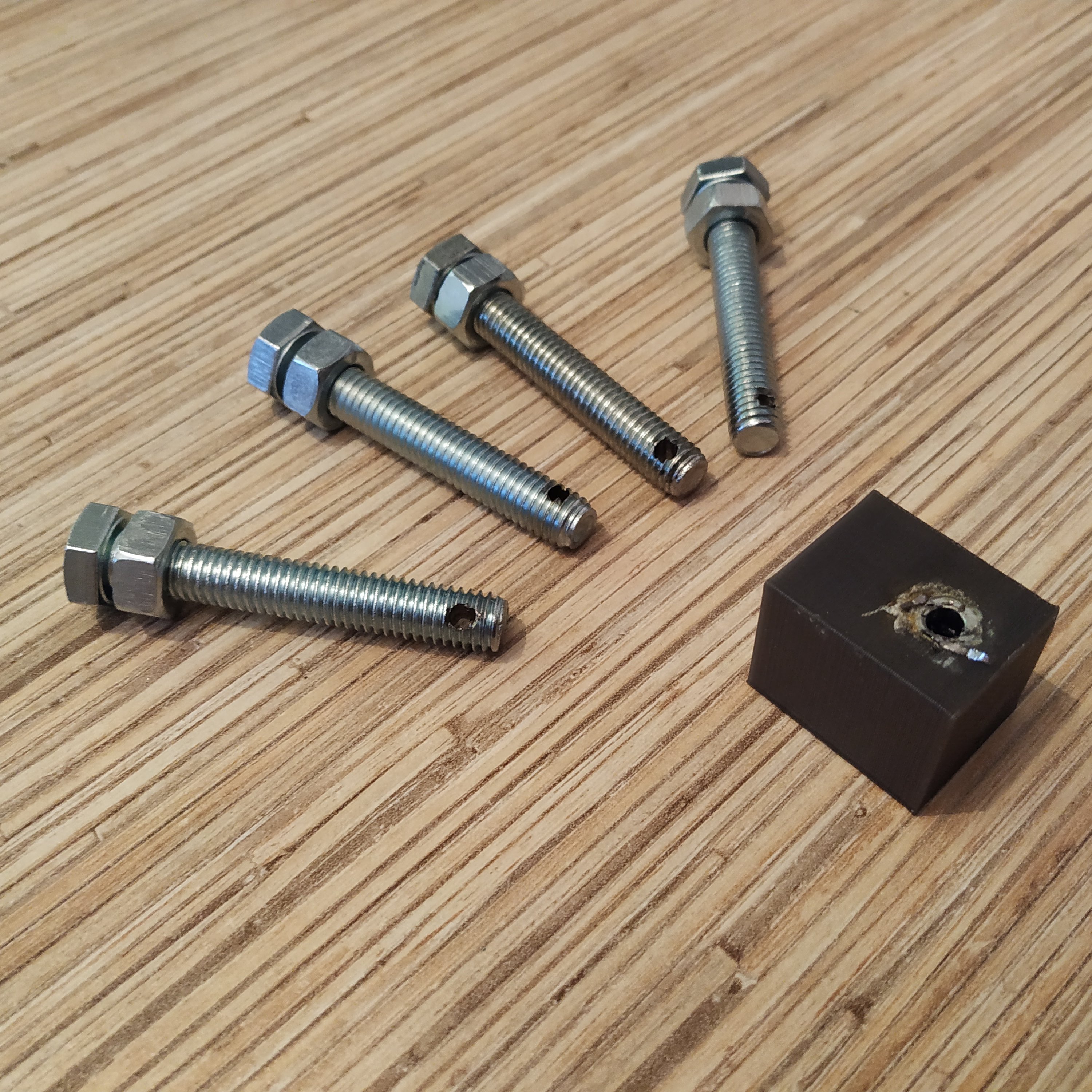
17. Using the provided printable drilling guide and an M4 nut press-fitted into it, drill holes in 4 M8x50mm bolts as shown in the picture below, and put nuts onto those bolts. While drilling, rinse the drilling guide with a bolt inserted in it with cold water often - the process will be much easier. Use moderate RPM of the drill to not let the drill guide to overheat.
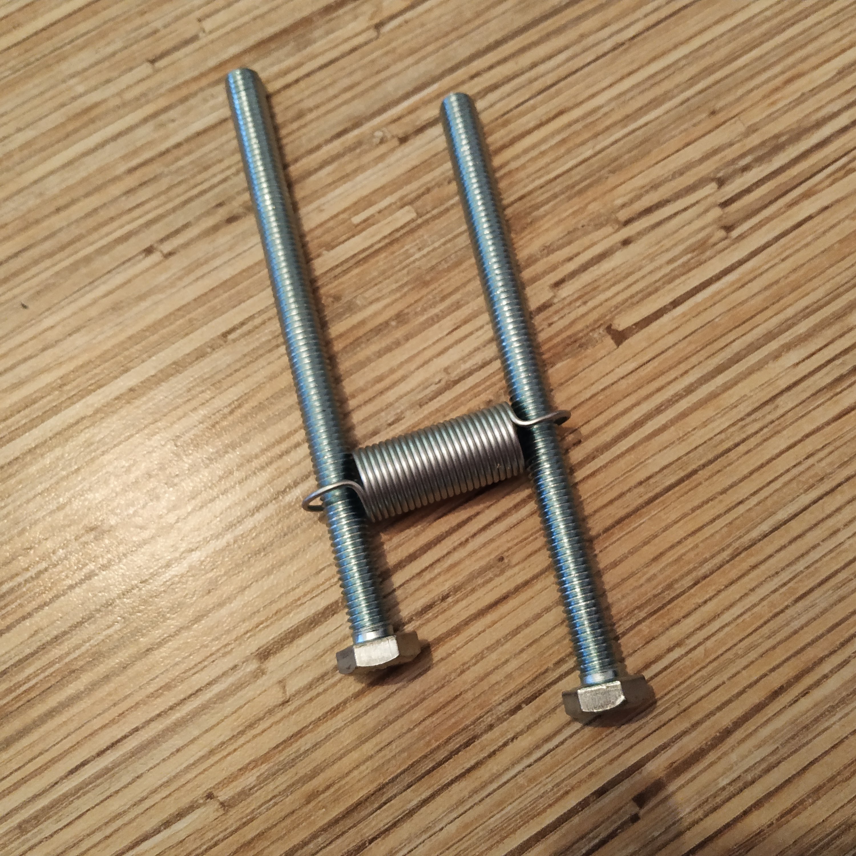
18. Install the bolts into spring holder arms. Put another nut onto each bolt.
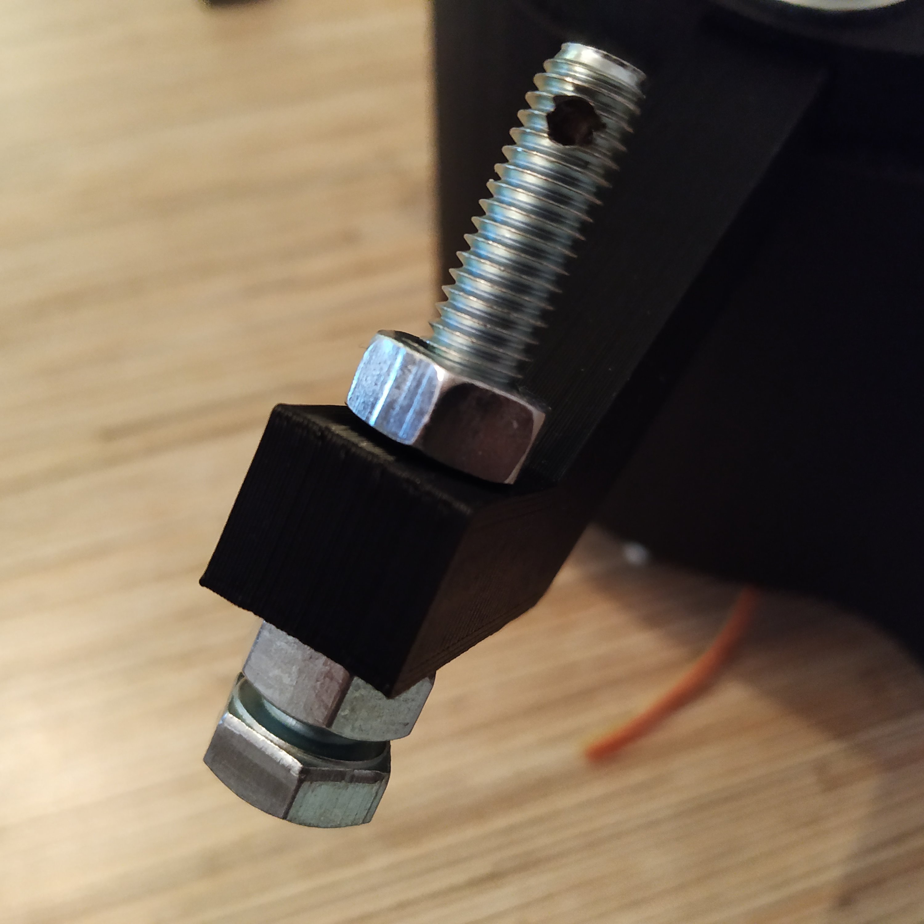
19. Take 4 springs and stretch each of them to smth close to 90mm. Install the springs.

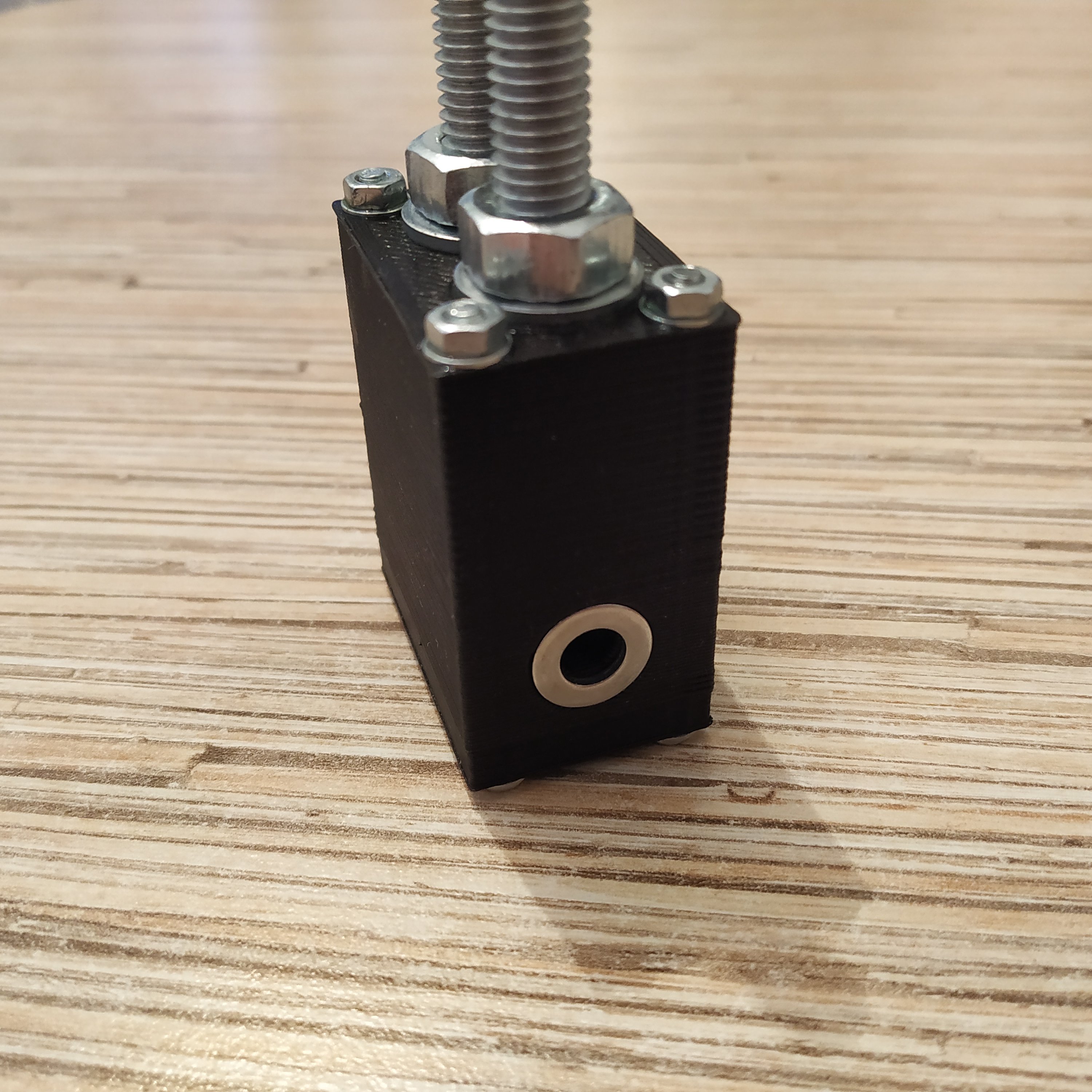
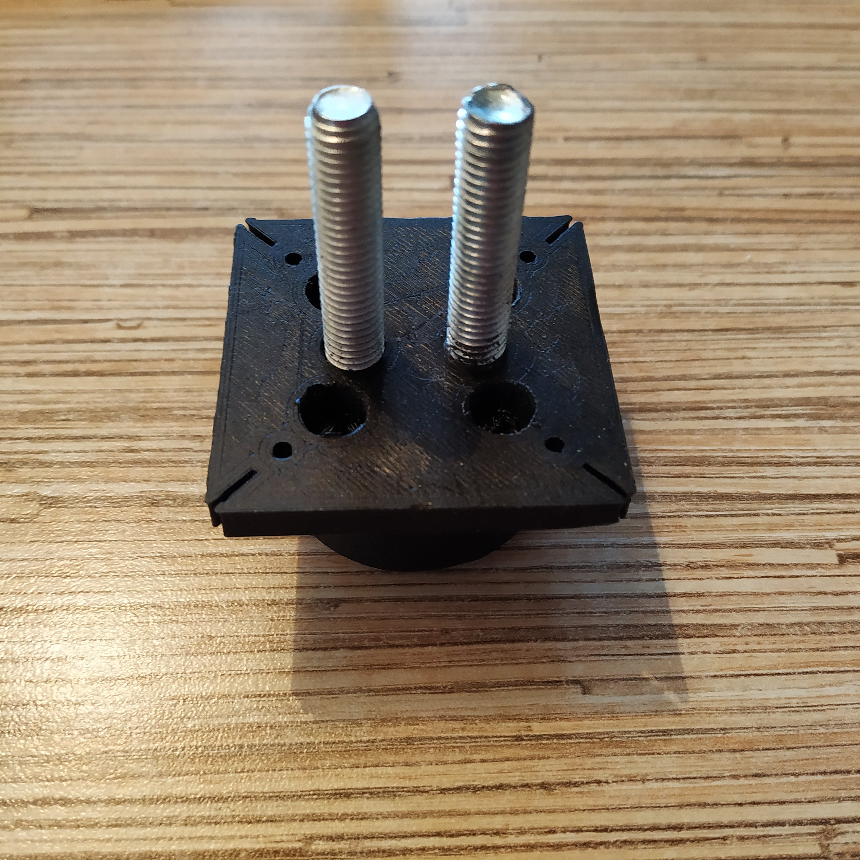
20. Insert 4 M8x75mm or M8x90mm bolts into the base lid depending on the version of the mounting bracket you choose (this manual will be based on the base with interchangeable mounting brackets). Put a washer and a nut onto each bolt.

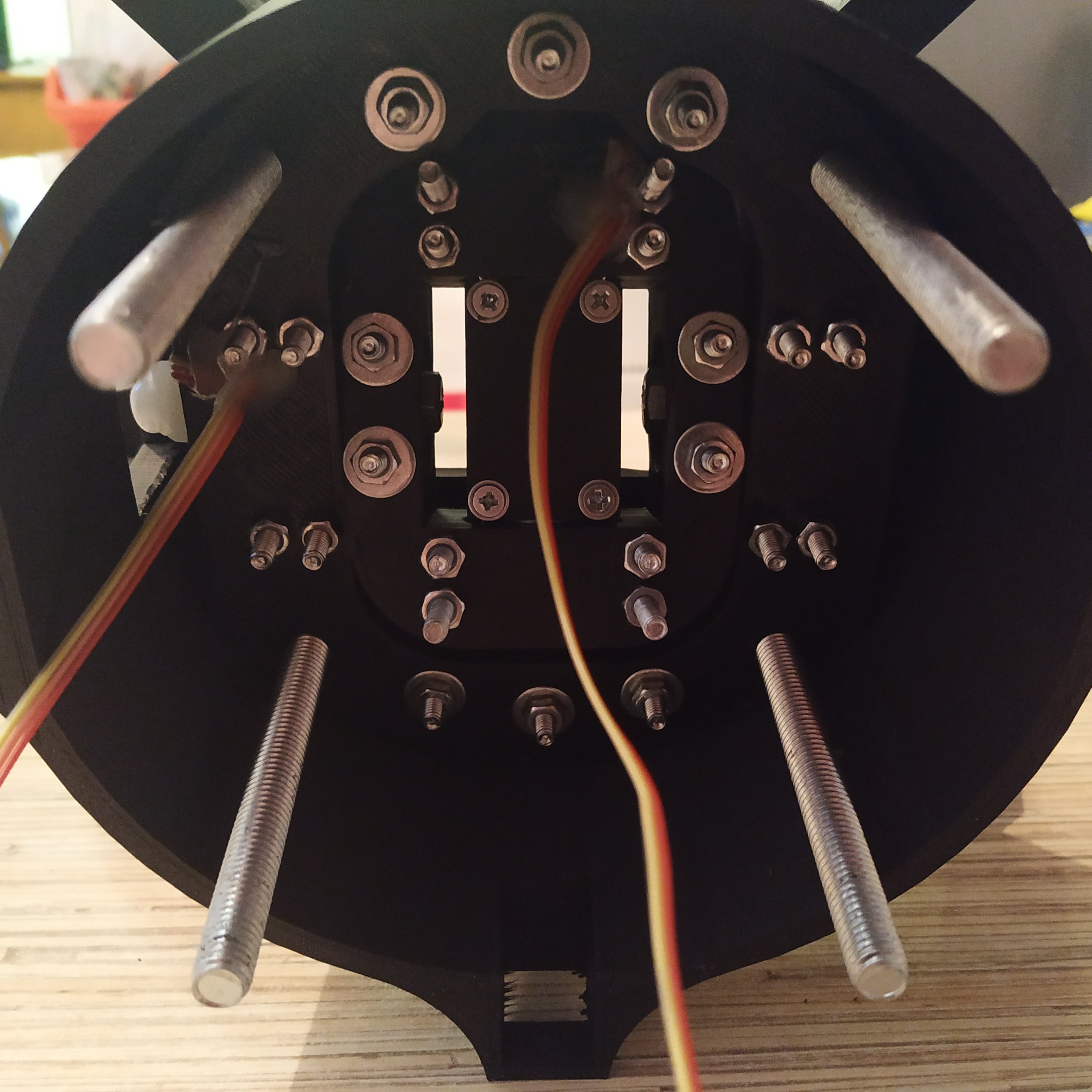
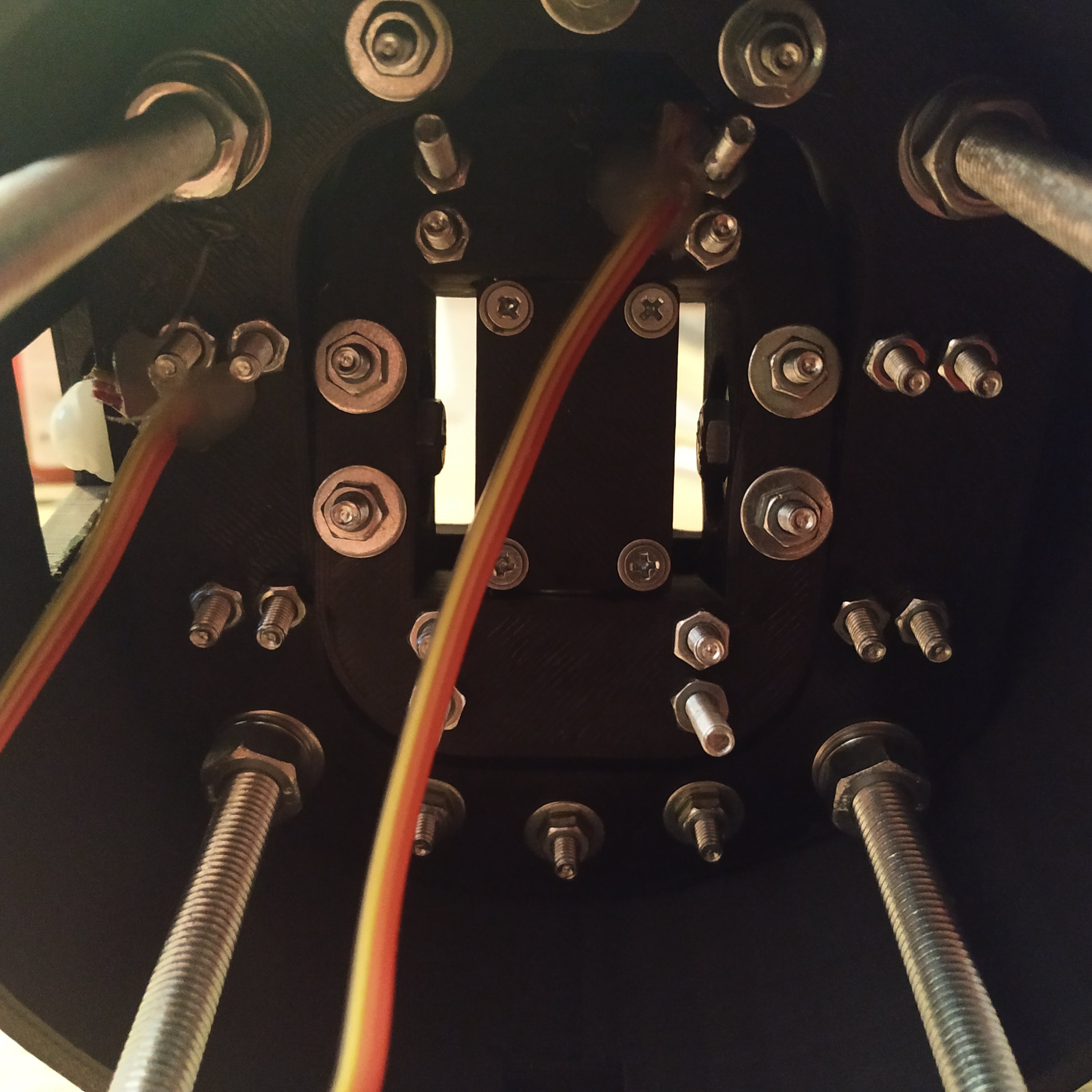
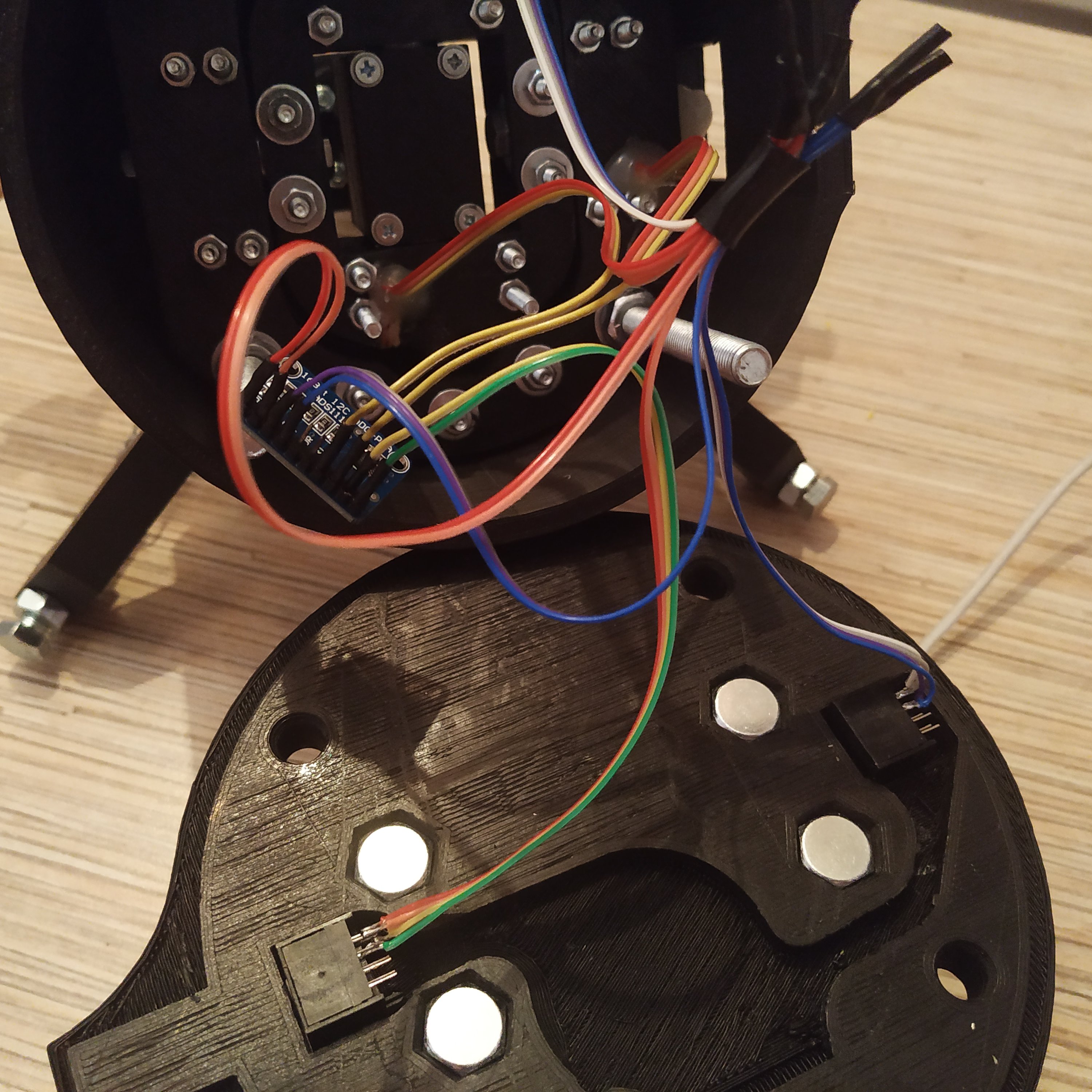
21. Solder 4 wires of the same color to 2 I2C Ethernet sockets and a header to the ADS1115 board. Solder 4 wires of a different color to ADC AUX socket.
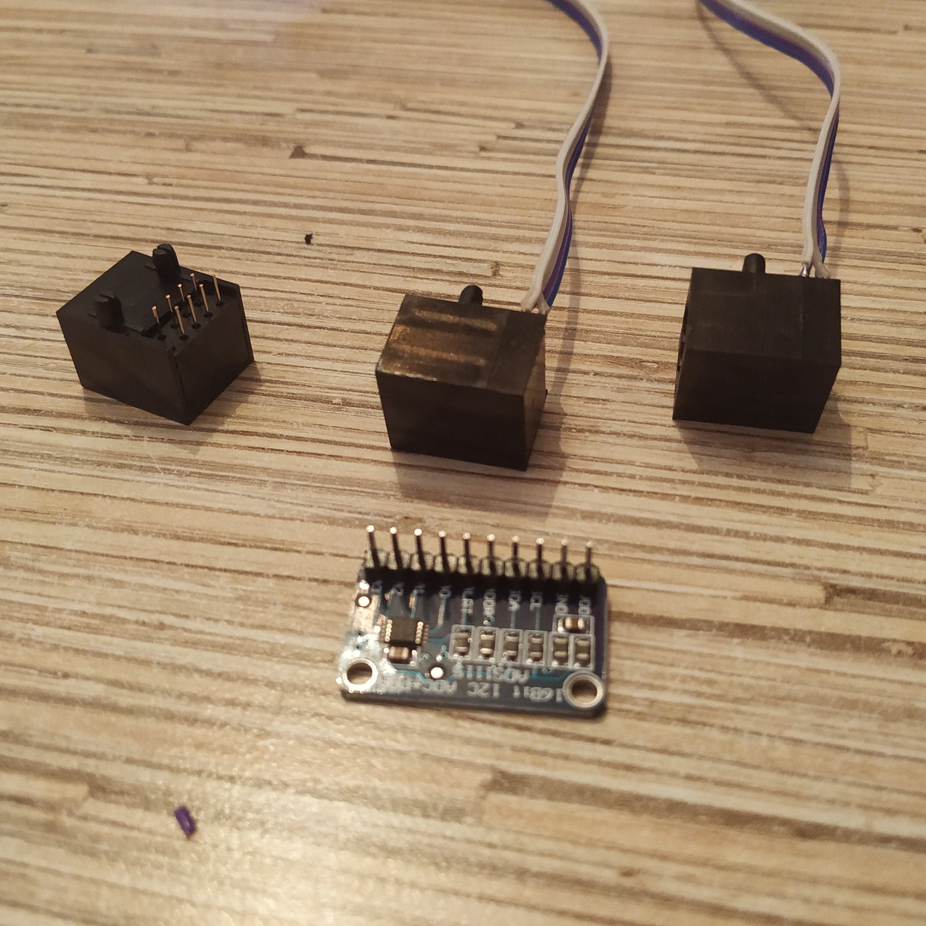
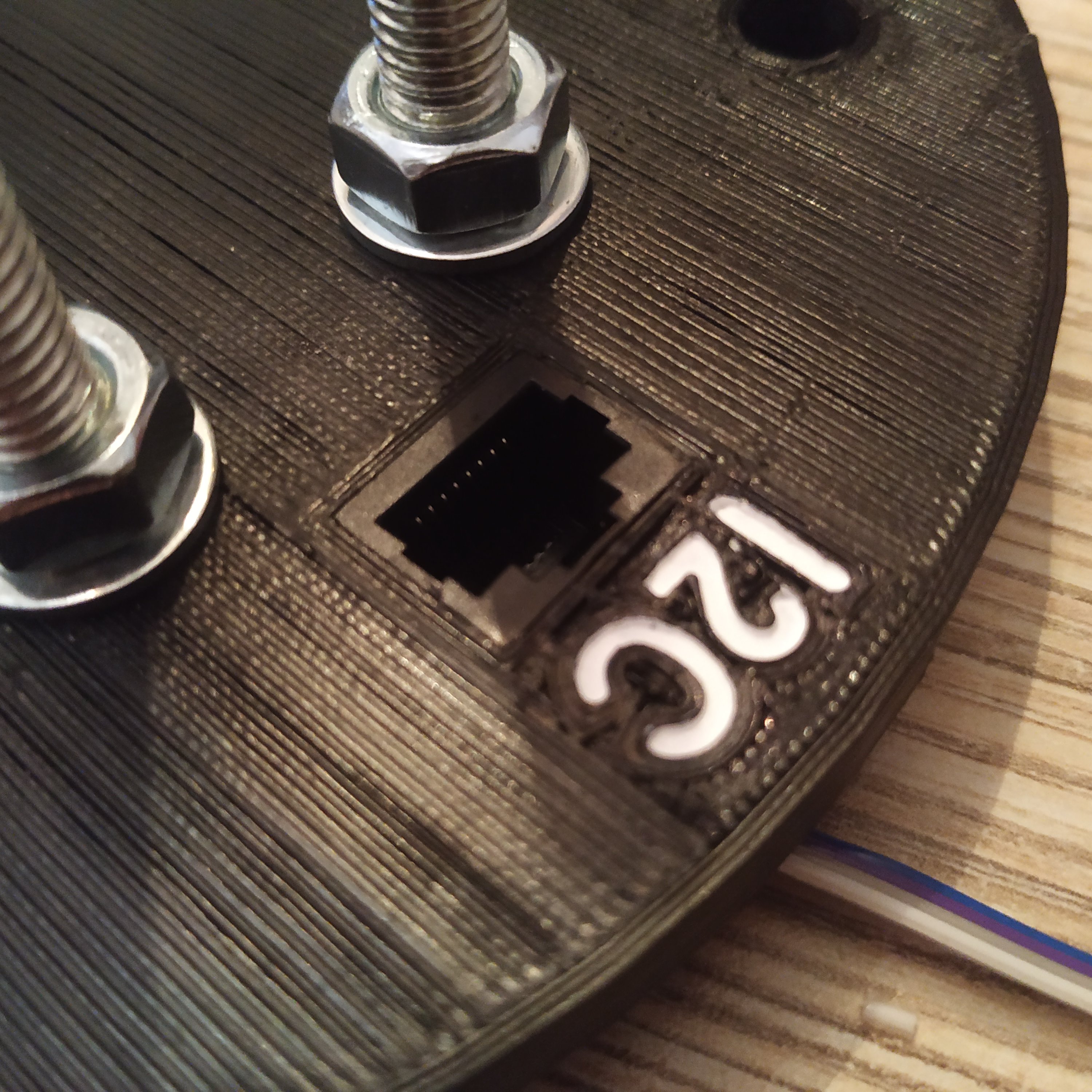
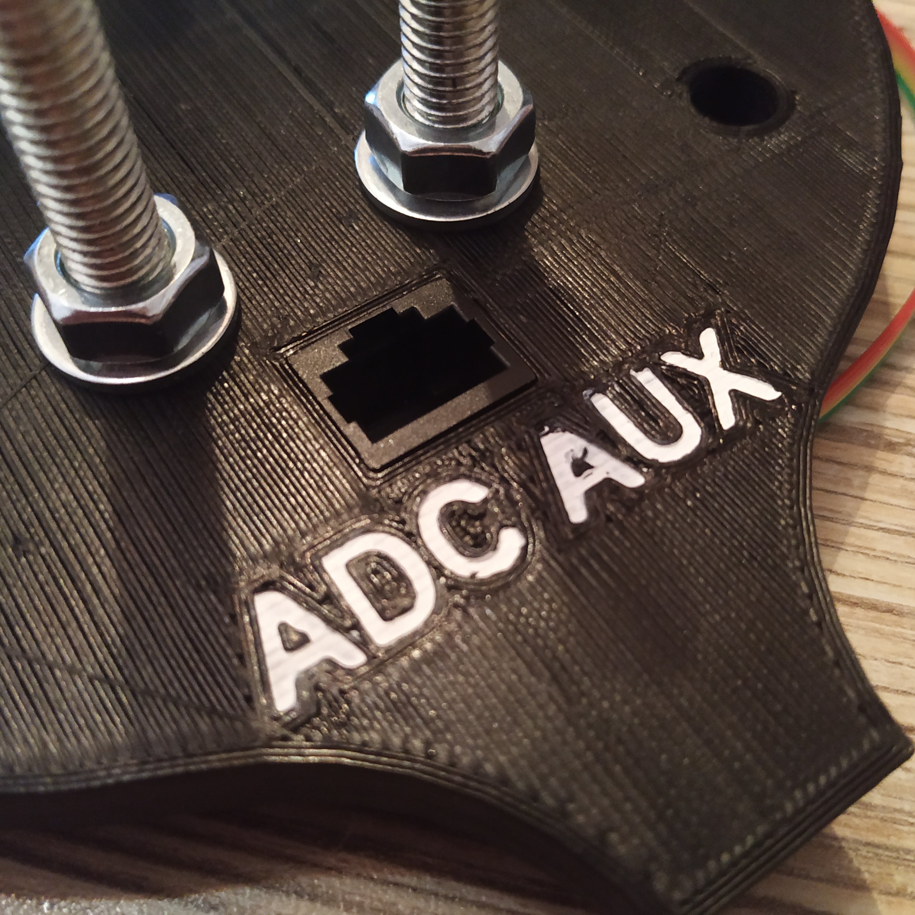
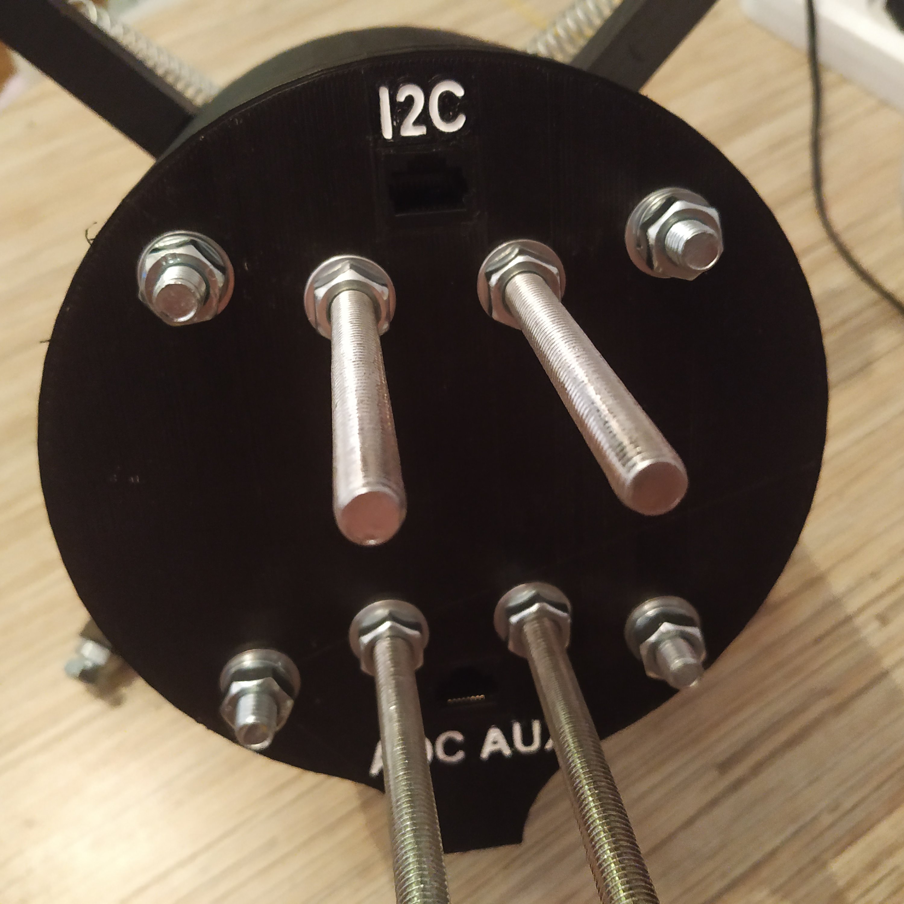
22. Insert one of the sockets into its slot in the base. Insert the other one to the I2C slot in the lid and the 3rd one into the ADC AUX slot.
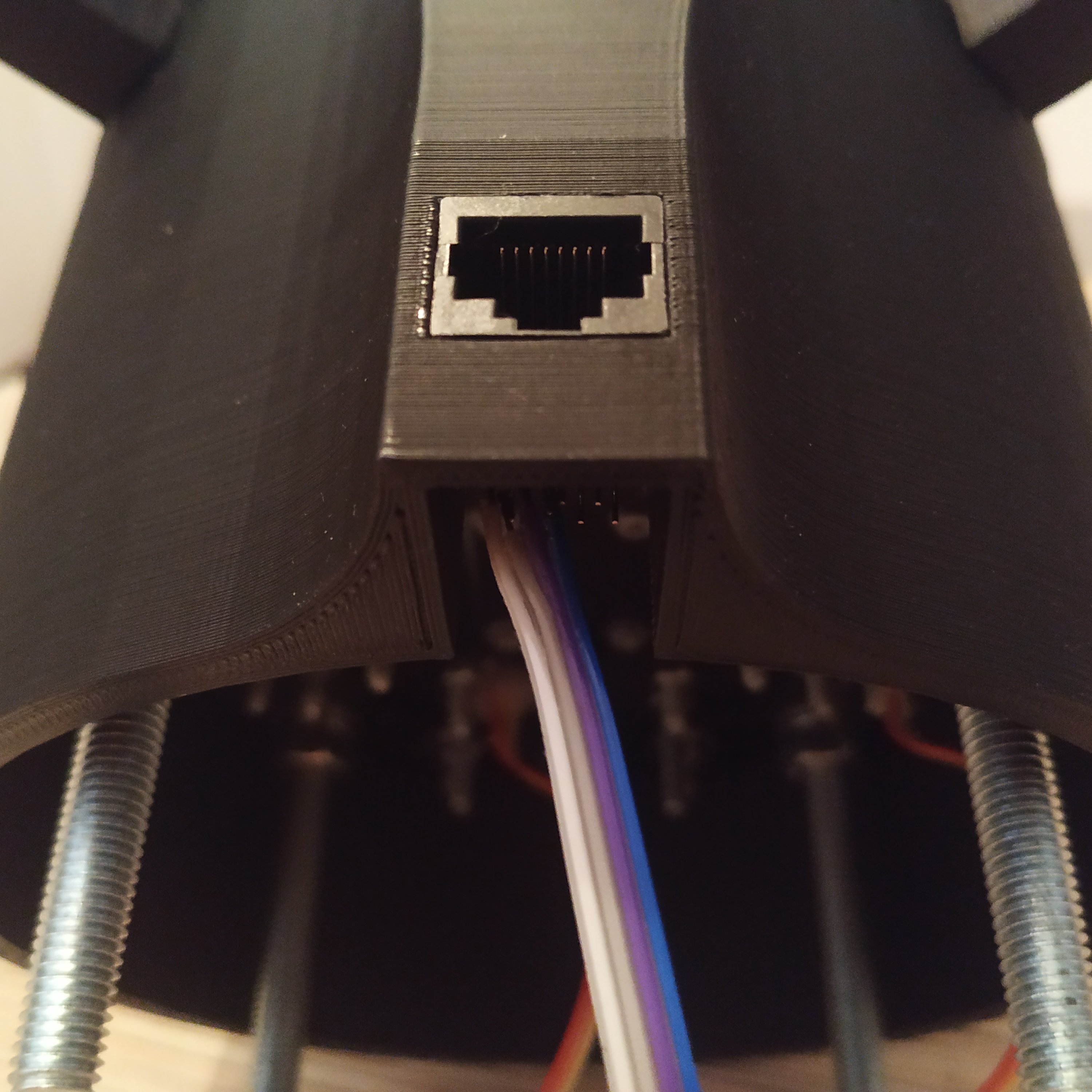

23. Assemble all VCC wires to a cable tie. Repeat with SCL and SDA wires. Route a 4-wire cable from the tie to ADS1115 board and solder all wires as follows:
VCC TIE                 -> ADS1115 VCC
GND TIE                 -> ADS1115 GND
SCL (SOCKETS PIN 3) TIE -> ADS1115 SCL
SDA (SOCKETS PIN 4) TIE -> ADS1115 SDA
SS495A1 X SGNL          -> ADS1115 A0
SS495A1 Y SGNL          -> ADS1115 A1
ADC AUX SOCKET PIN 3    -> ADS1115 A3
ADC AUX SOCKET PIN 4    -> ADS1115 A4

24. Assemble the RATES panel using its manual.
25. Time to check everything! Hook the base to the master controller, uncomment
#define CYCLIC_BASE in its firmware and check joy.cpl.
BE CAREFUL, REVERSING POLARITY ON SS495A SENSORS WILL FRY THEM IN SECONDS!
MAKE SURE YOUR POLARITY IS CORRECT BEFORE CONNECTING THE BASE TO THE MASTER!
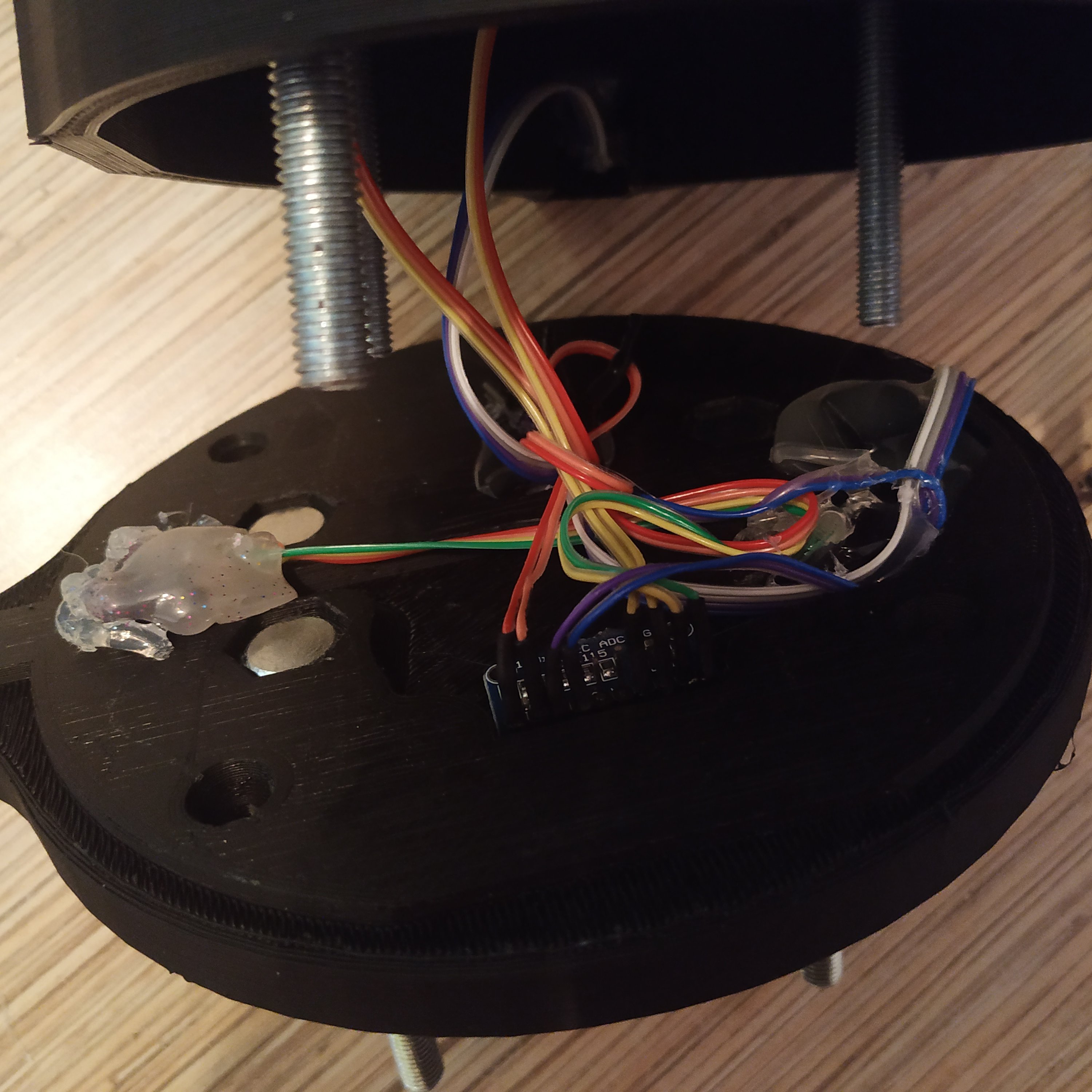
26. If everything works, fix sockets and the ADC board with hot glue and put the lid on. Fix it with 4 nuts, use regular washers along with spring washers.
27. Put a nut, a spring washer, and a connector nut onto each bolt of the stick connector.

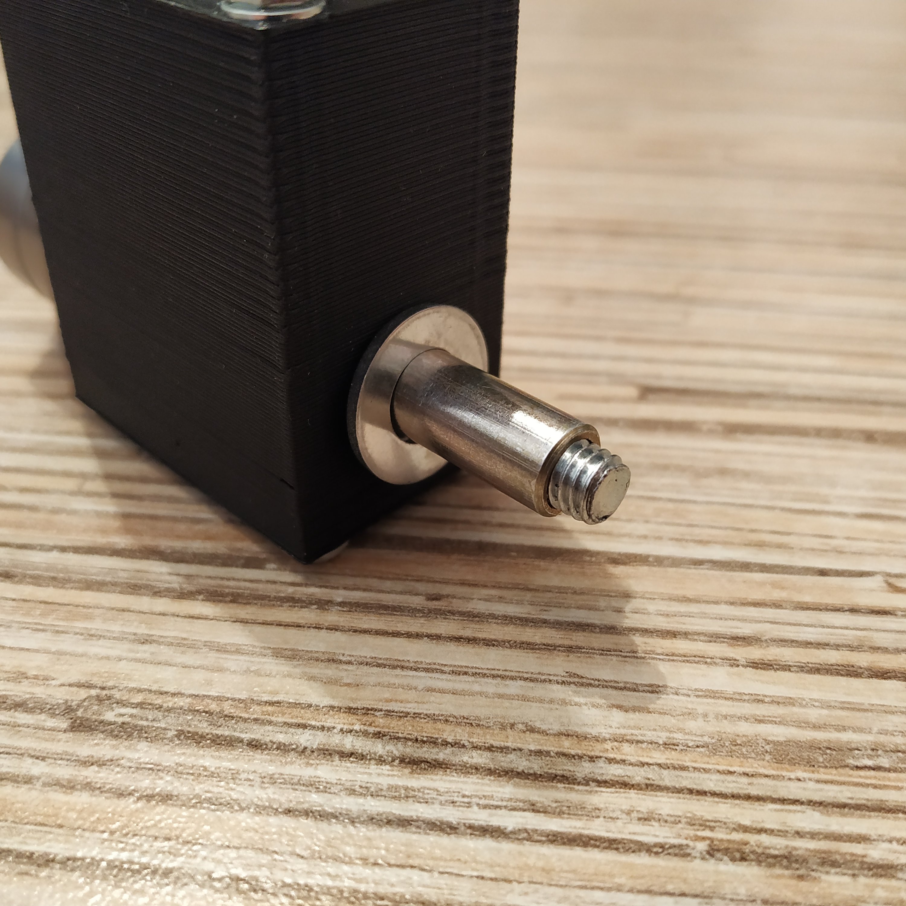
28. Attach the mount if applicable to your chosen version of the base and put a magnet hatch side cover on.
Congratulations, the base is finished! Don't forget to hook up the rates panel, set it to 100% and go for a test flight!