Table of Contents
MKIV MASTER CONTROLLER
Summary
The MKIV master controller is designed to be stackable - unlike the MKIII version, we can use any number of them and assign any device to any controller. Standard helicopter setup fits a single board - even with the VRMaxII pedestal. If you feel that you want a faster response from the controls, just add another box and move some of your devices there. Please remember, that for the force trim and sensitivity switch to work, both the cyclic and the pedals need to belong to the same master.


Components
- 1 x Arduino Leonardo
- 1 x FTDI232 USB-UART board
- 1 x 6x6x5mm tactile button
- 4 x TJ8P8C Ethernet sockets (12,5x15x17,6mm)
- 4 x M3x30mm screw
- 2 x M3x40mm screw
- 4 x M3x6mm screw
- 6 x M3 nuts
- A ribbon cable


Downloads
Assembly guide
1. Solder the reset button wires to a 6x6x5mm tact button.

2. Put the RST button into its socket in the controller box, fix it with hot glue.


4. Install the Leonardo board into the box, fix it with 4x M3x6mm screws.

5.
- Solder 4 4-wire cables to Ethernet sockets
- Add 5th 4 wire cable and make a cable tie (tie wires of the same color together and solder them).
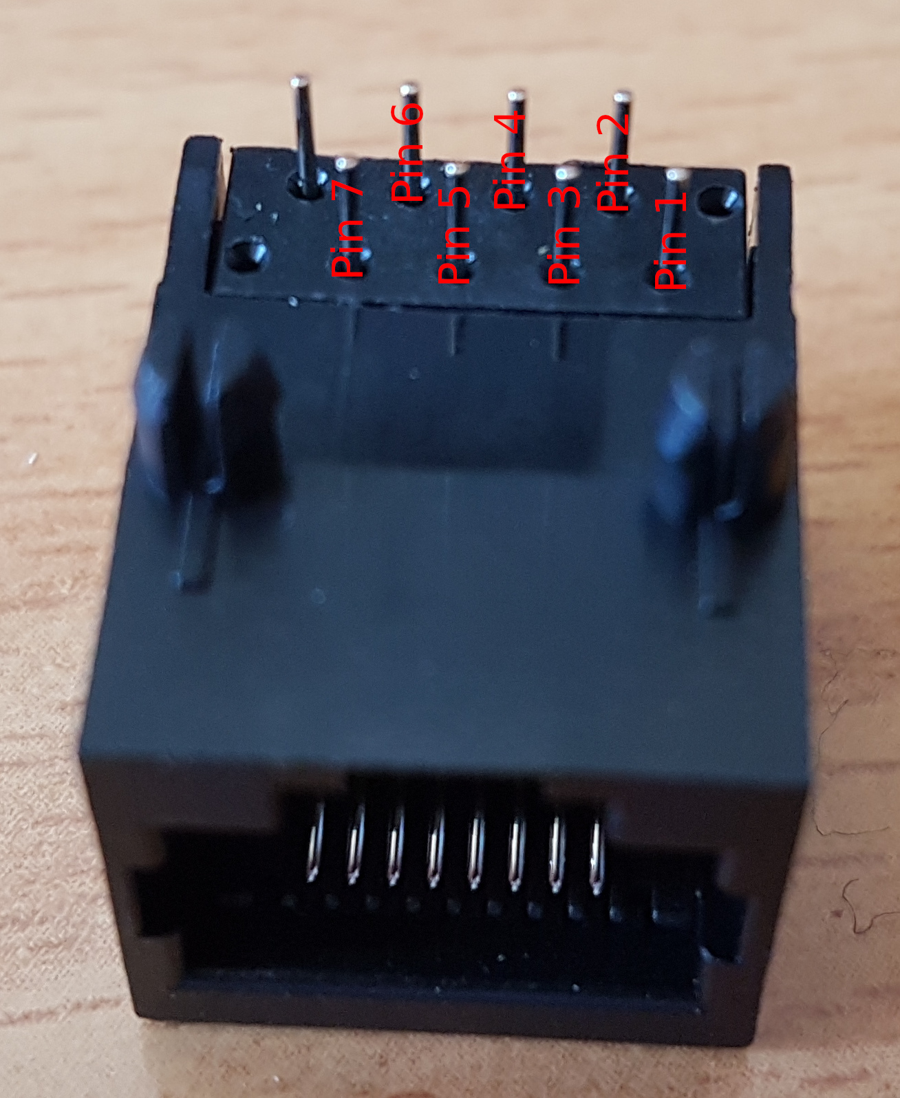
- Cover ties with thermal shrink tube. Pin 1 is where the white-orange wire of an Ethernet cable will go.


6. Put sockets into their slot in the controller box.

7. Cut an 8-pin connector and solder wires as follows:
- SOCKET PIN 1 (white-orange wire of Ethernet cable) → 5V
- SOCKET PIN 2 (orange wire of Ethernet cable) → GND
- RST BTN PIN 1 → RST (polarity does not matter here)
- RST BTN PIN 2 → GND
Put a thermal shrink tube and some hot glue onto wires to fix them. Insert the header into the Leonardo board.

8. Solder a 2-pin connector to SDA and SCL wires and connect them to their sockets. SCL pin (Ethernet socket pin 3) is the closest one to RST button on the board.
- SOCKET PIN 3 (white-green wire of Ethernet cable) → SCL
- SOCKET PIN 4 (blue wire of Ethernet cable) → SDA


9. Flash the controller with the master controller firmware from simchair4_software repo and connect a peripheral to it to check if it works. Check every socket this way. If everything is fine, proceed.
10. Do some cable management and fix sockets with hot glue. Be careful not to pour glue onto lid screw holes. Don’t worry if this happens though, hot glue can be easily removed mechanically after it will dry.


11. Put 2 M3x40mm screws into their sockets, fix with nuts:

12. Put the lid onto the controller box and fix it with 4 M3x30 screws.

13. Put mounting brackets on and add nyloc nuts. The controller is finished!


Congratulations, your master controller is finished! :)
You will now need to make a small accessory to flash peripherals.
USB – Ethernet cable for flashing peripherals
The FTDI232 USB-UART board is used to flash most of MKIV peripherals. In fact, you can, of course, use any other, however, if it does not have a DTR pin, you will need to press the reset button on the peripheral manually during flashing.
Note that some devices (like the compact head) still need to be flashed through their UART header, so solder wires to the back part of pins so you can still use jumper wires to connect the header to Pro Mini board.

WHITE-ORANGE -> FTDI232 VCC
ORANGE -> FTDI232 GND
WHITE-GREEN -> NC
BLUE -> NC
WHITE-BLUE -> FTDI232 TX
GREEN -> FTDI232 RX
WHITE-BROWN -> FTDI232 DTR
BROWN -> NC


Finally, everything should be complete! :)
