This is an old revision of the document!
Table of Contents
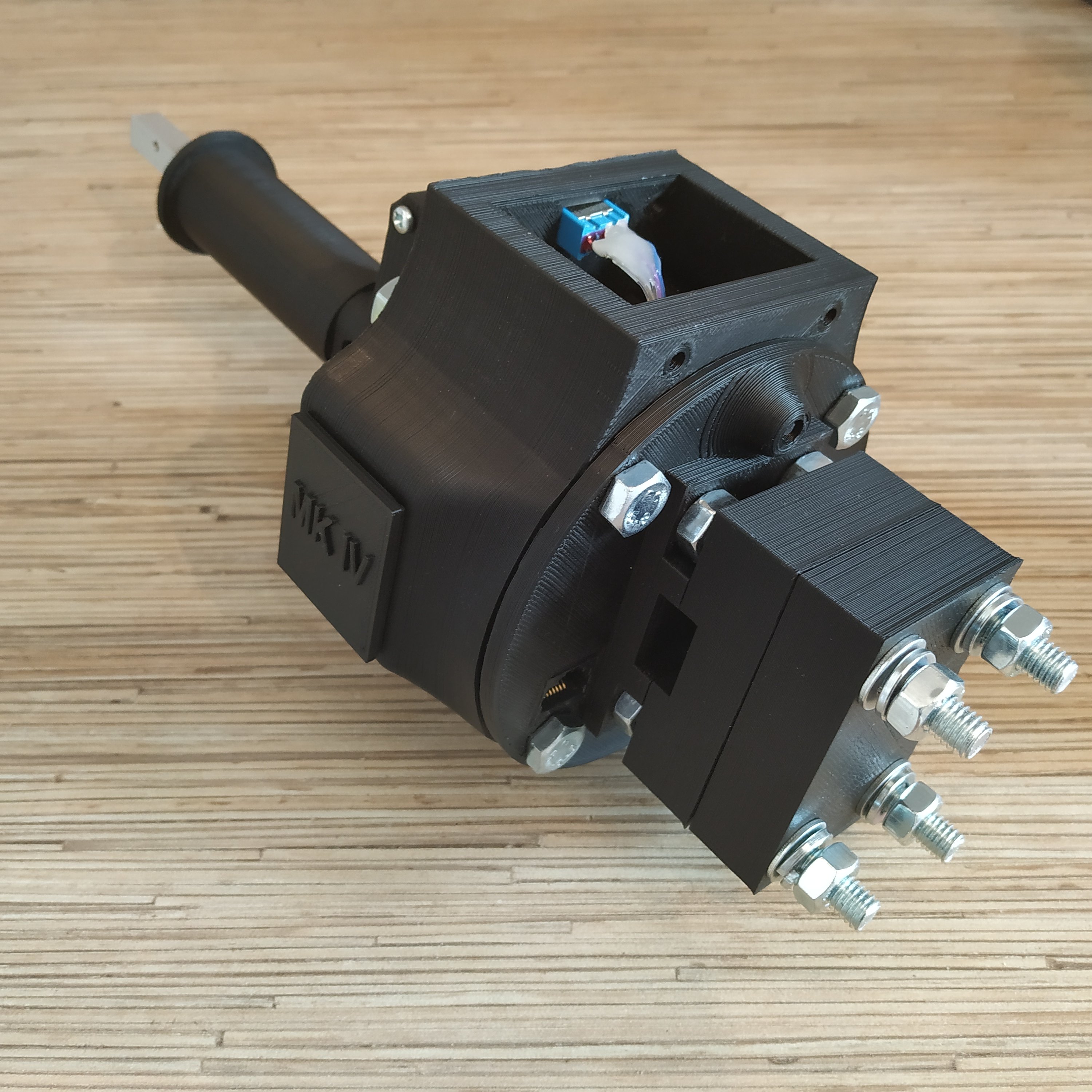
Simchair MKIV collective lever base
Components
- 1 x 10x10mm aluminum square pipe
- 1 x 20×10 aluminum rectangular pipe
- 1 x SS495A1 hall sensor
- 1 x MTS-103 ON-OFF-ON switch
- 1 x 16K1 10KOhm LINEAR rotary potentiometer
- 1 x 6x6x4mm square magnet
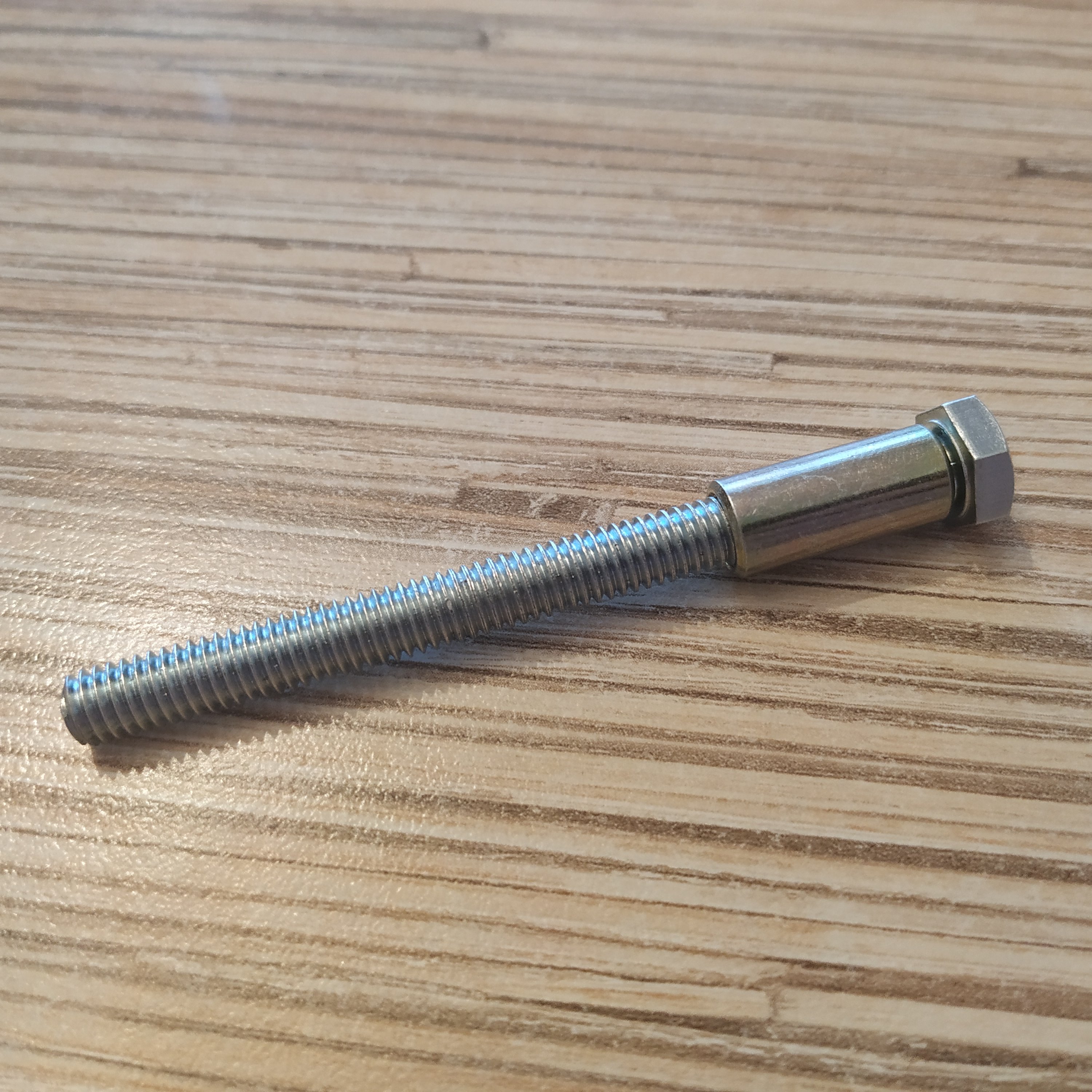
- 1 x M6x70mm screw
- 2 x M6 washers (reinforced)
- 1 x M6 nut
- 2 x M6x18x8mm hubs
- 6 x M4x40mm screws
- 4 x M4x70mm screws
- 1 x M3x20mm screw
- 1 x M3 nyloc nut
- 4 x M4 nyloc nuts
- 4 x M3x50mm screws for tensioner halves contraction
- 4 x M8x70 bolts
- 4 x M8x75mm bolts
- 8 x M8 nuts
- 10 x M8 washers (regular, non-reinforced)
- 4 x M8 spring washers
- 1 x bag of M4 nuts
- 4 x 608 bearings (standard skateboard bearings)
- 1 x Arduino Pro mini
- 1 x Simchair MKIV Master controller
- super glue (cyanoacrylate), hot glue gun
Files location in repos
simchair4_models\printable components\peripherals\helicopter\collective lever\a_base - models
simchair4_software\peripherals - choose the preferred variant of the lever - software
Assembling manual
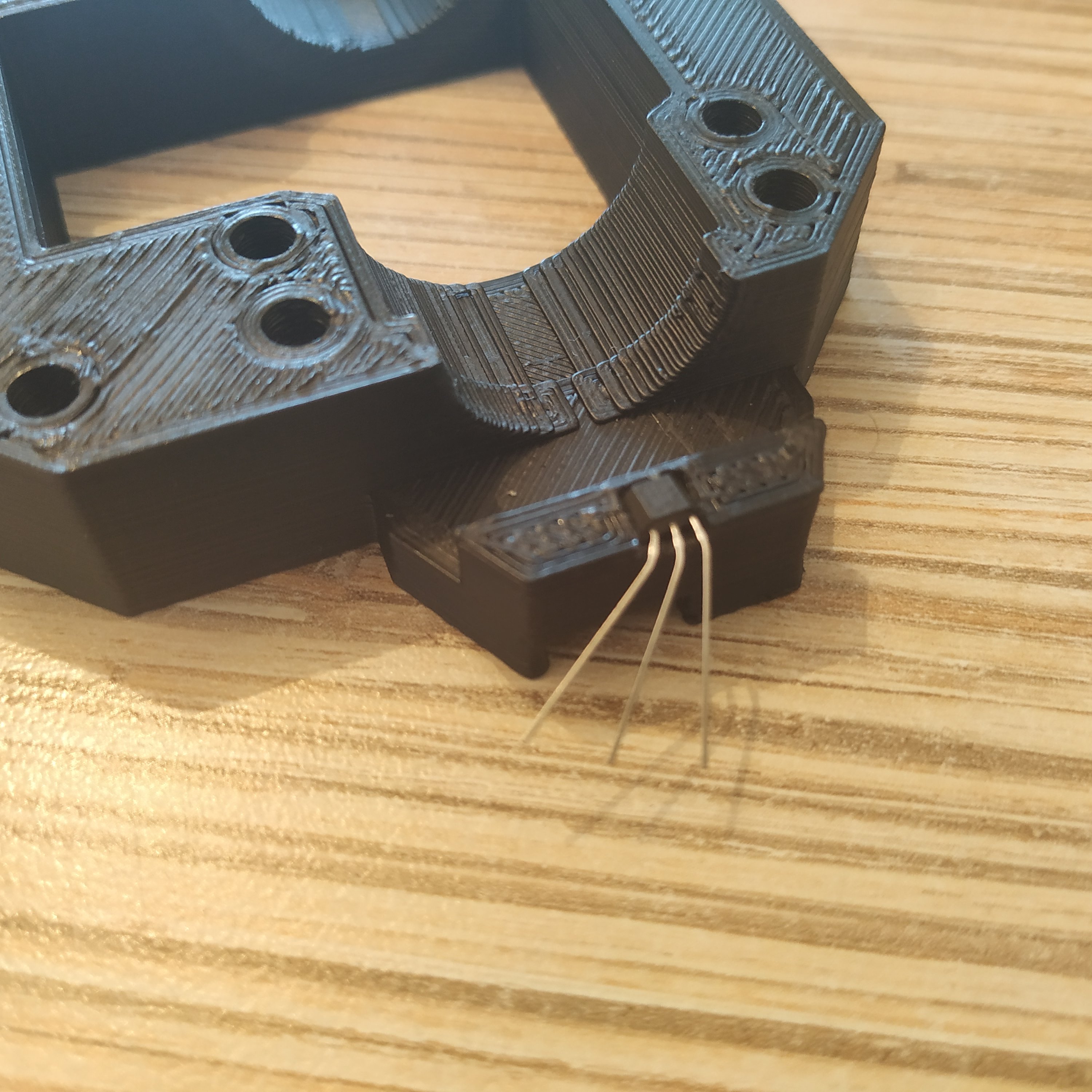
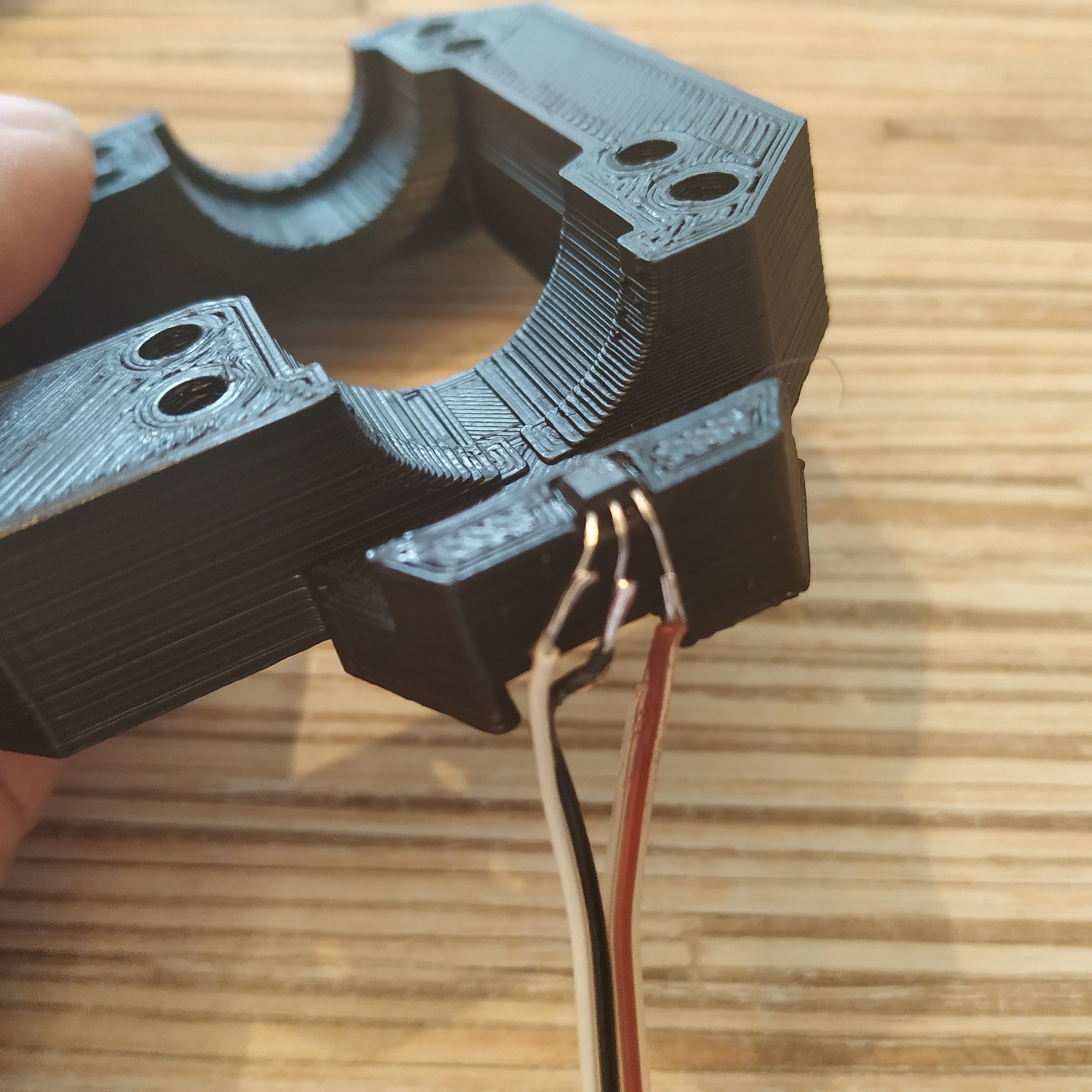
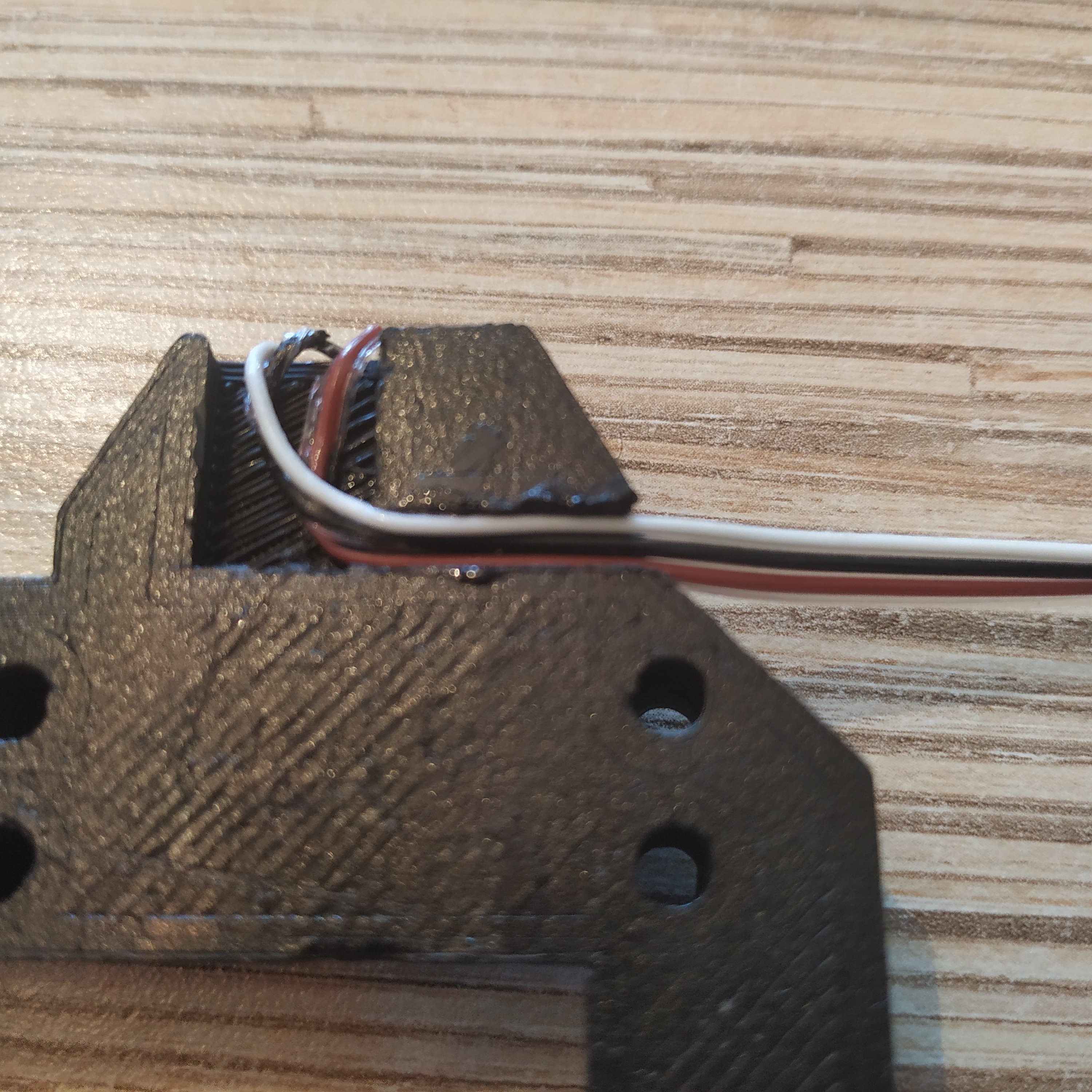
1. Insert SS495A1 into its socket in the top part of the lever frame (use a drop of super glue to fix it there) and solder its wires. Route wires as shown on the 3rd picture, use some glue as necessary.
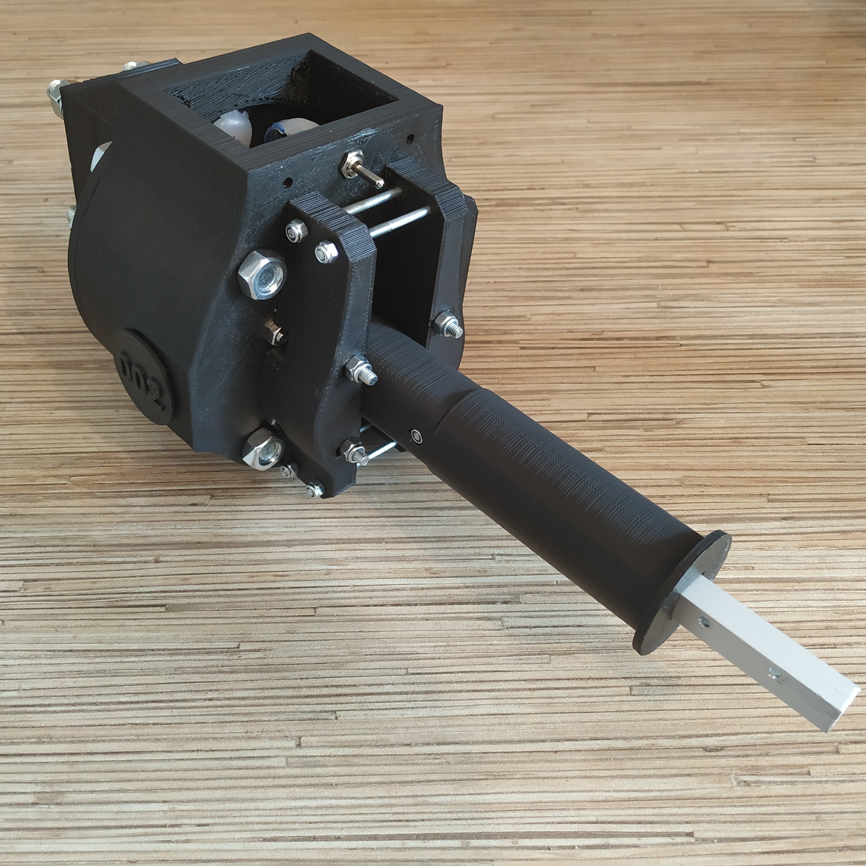
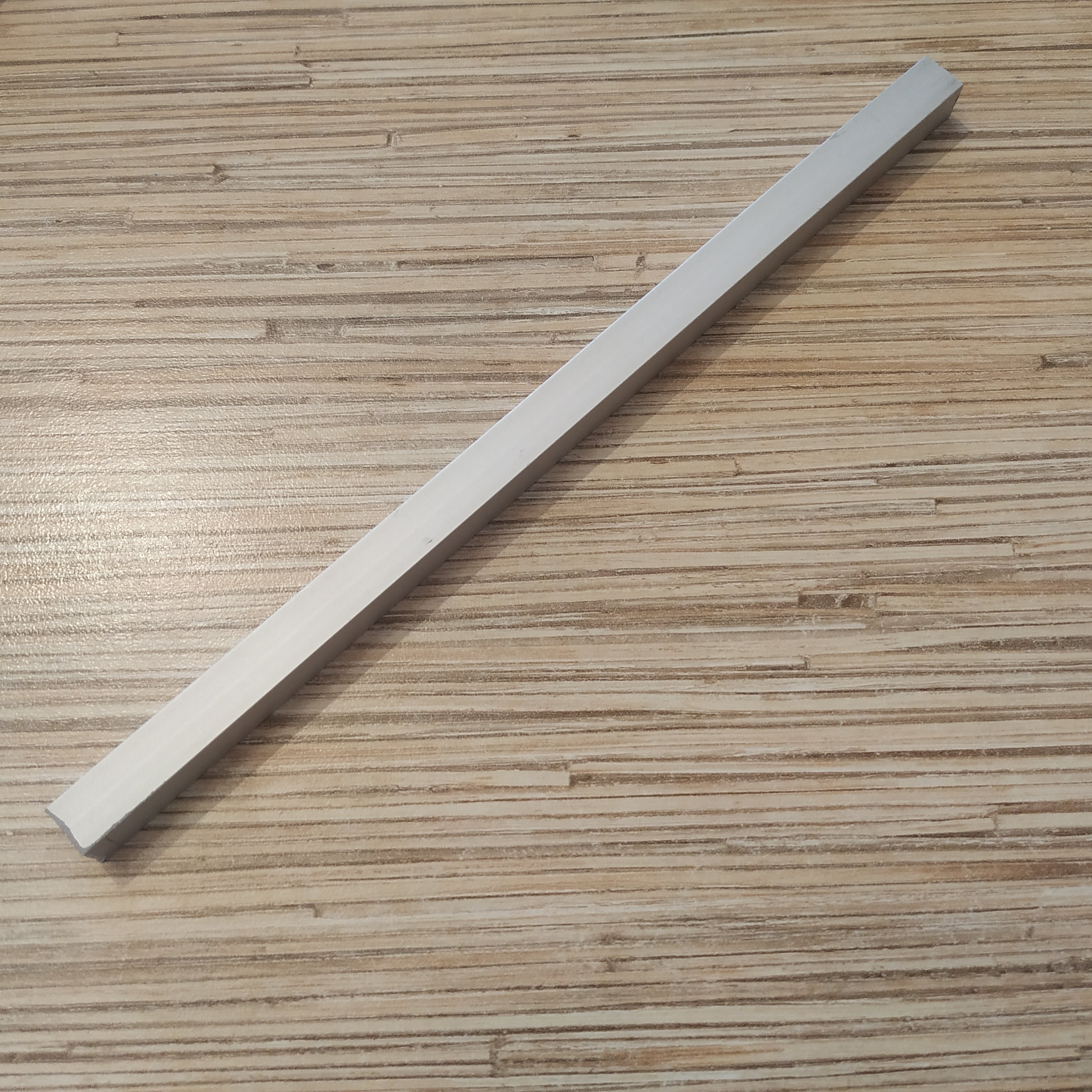
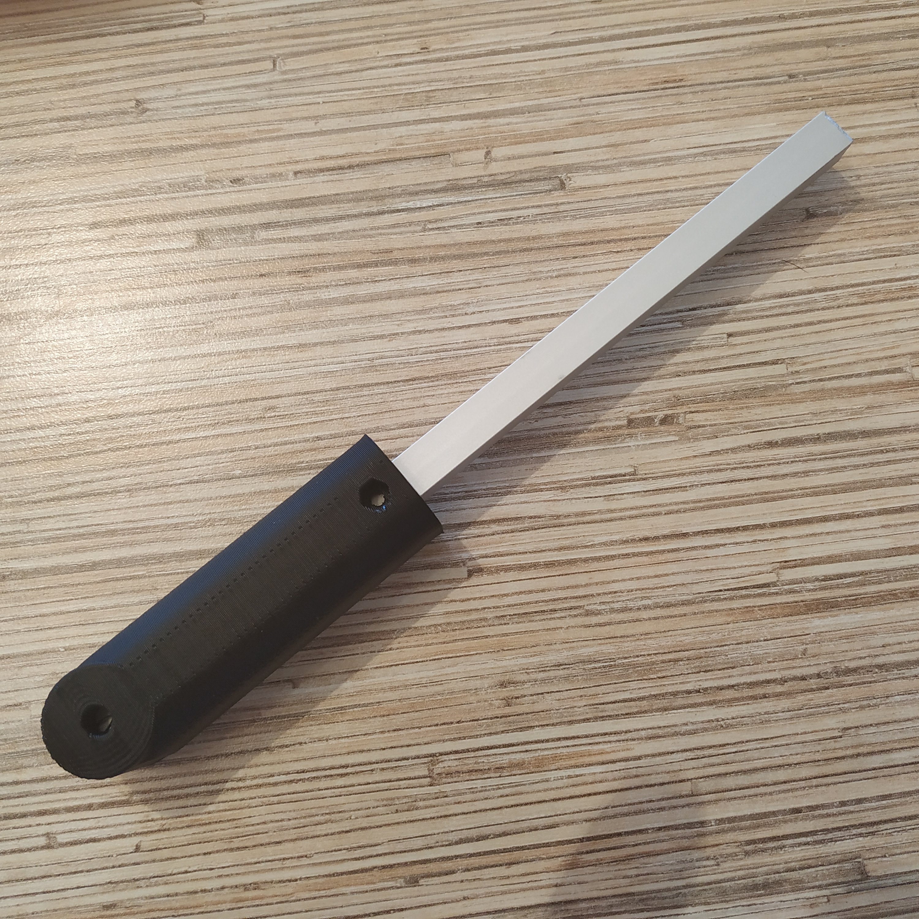
2. Cut off a piece of 10mm square aluminum profile. Choose the length depending on the lever you want to build (as stated in the lever body manual, e.g. 200mm for a single throttle lever)
3. Put the lever connector part onto the rail.
4. Drill a 3mm hole through the rail and insert an M3x20mm screw with a nyloc nut.
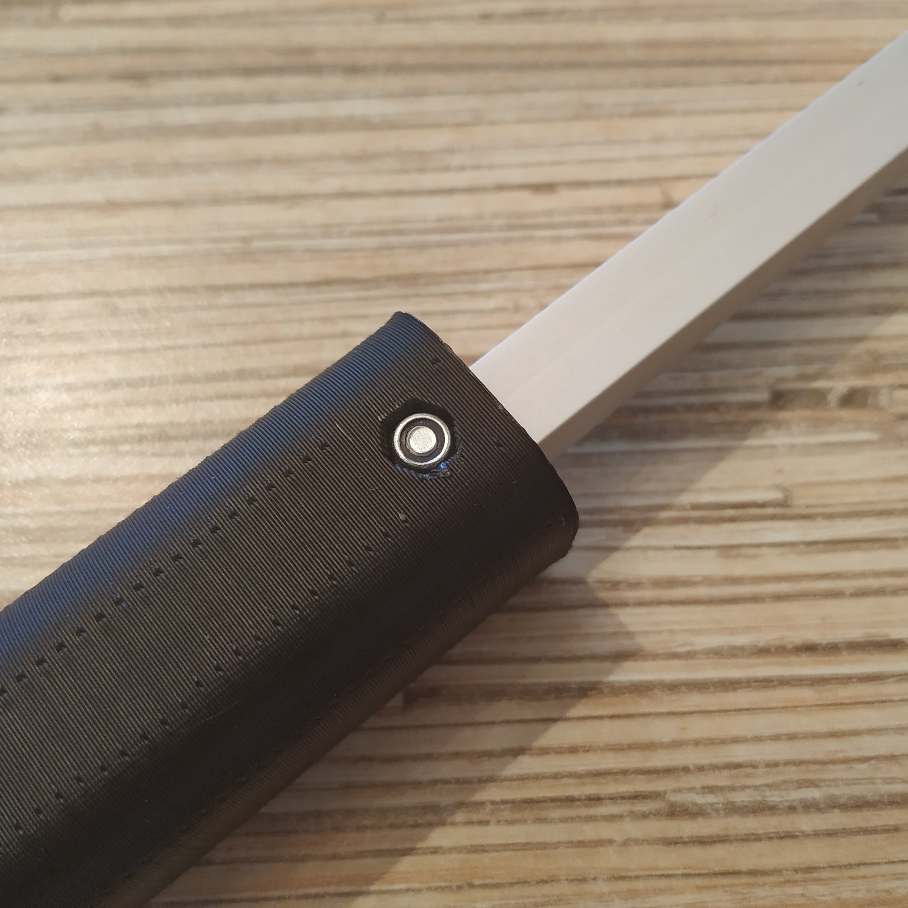
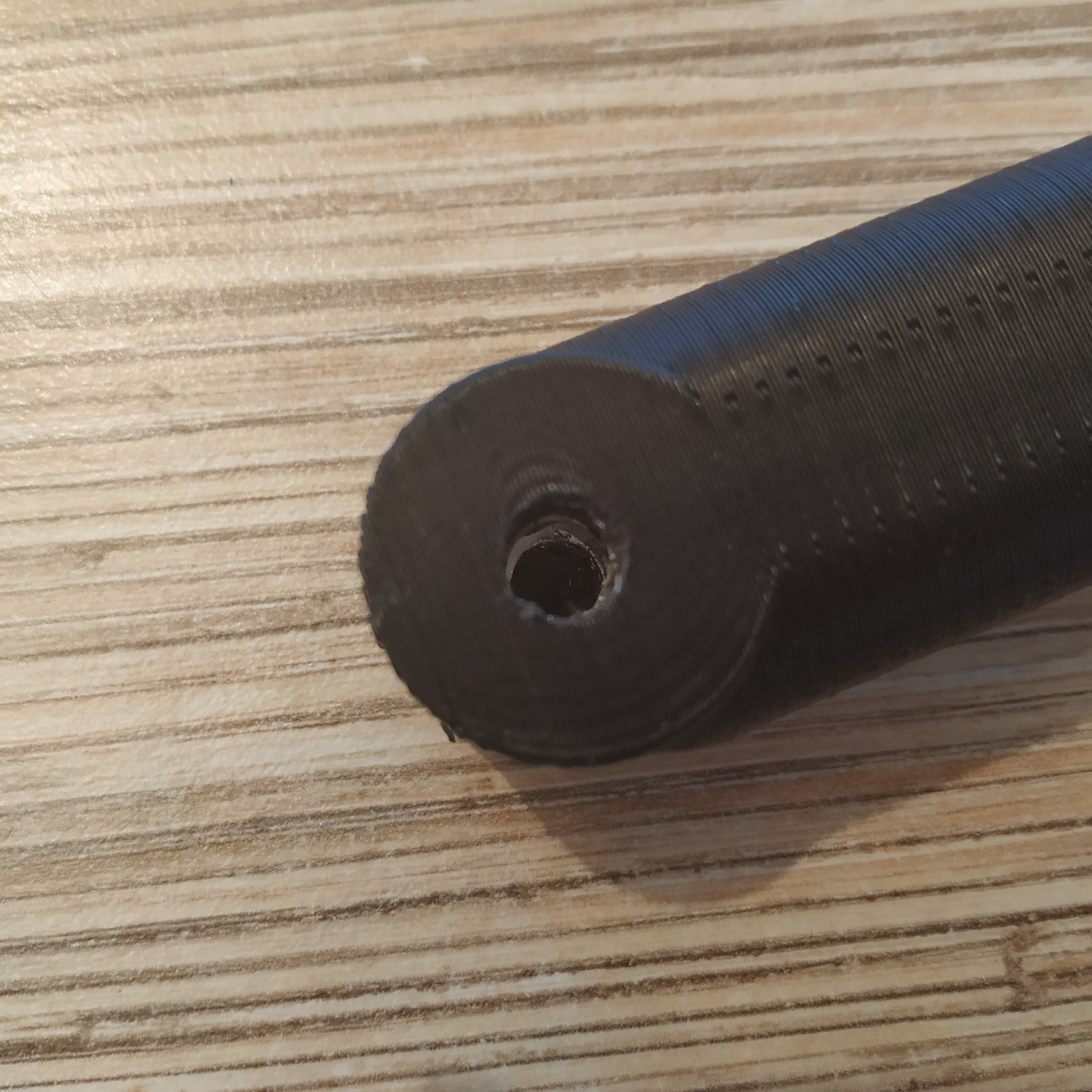
5. Drill a 6mm hole for the axis through the rail with a 5,5mm drill.
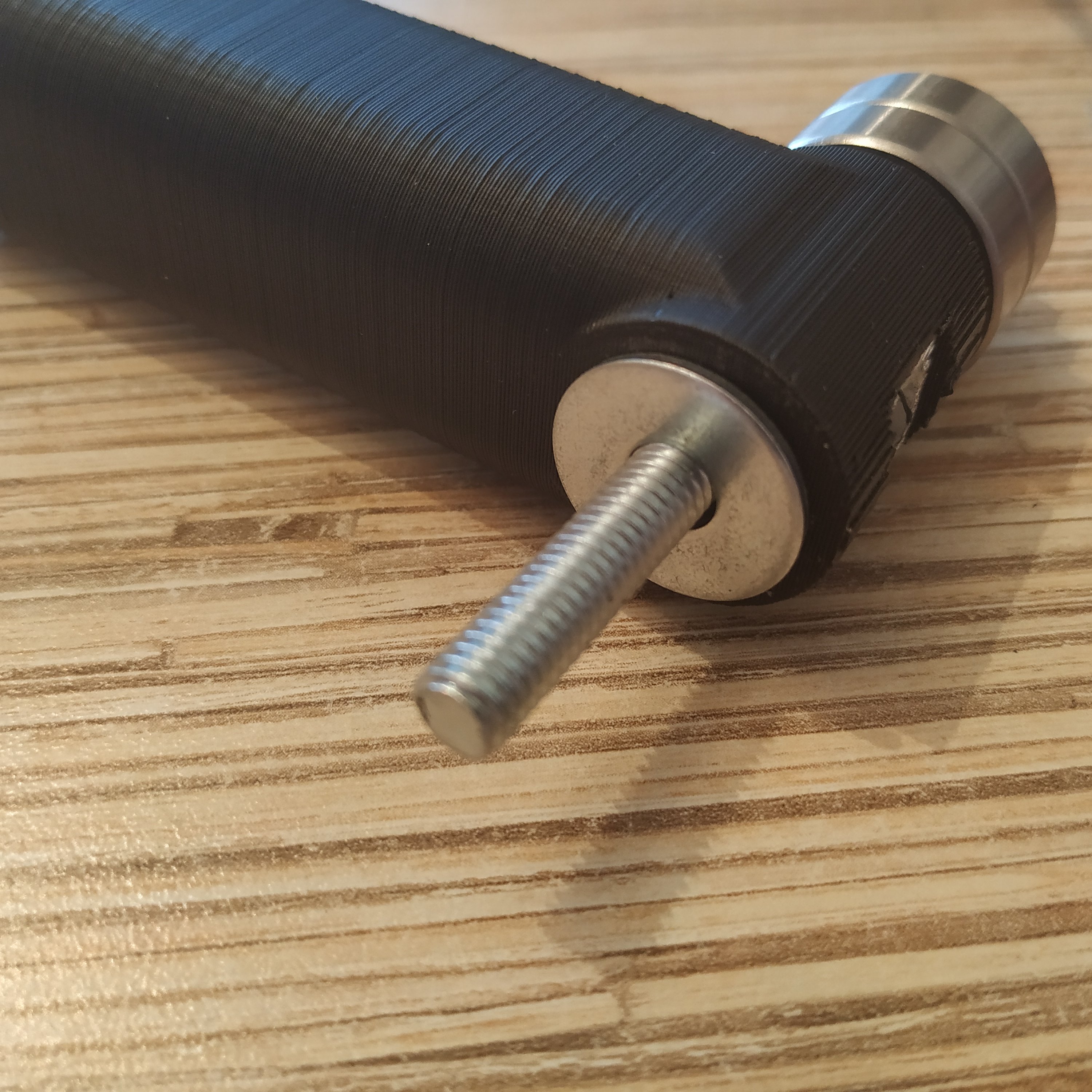
6. We will be assembling the lever axis. Start with putting an M6x8x18mm hub onto an M6x70mm bolt.
7. Put 3 M8 washers onto the hub
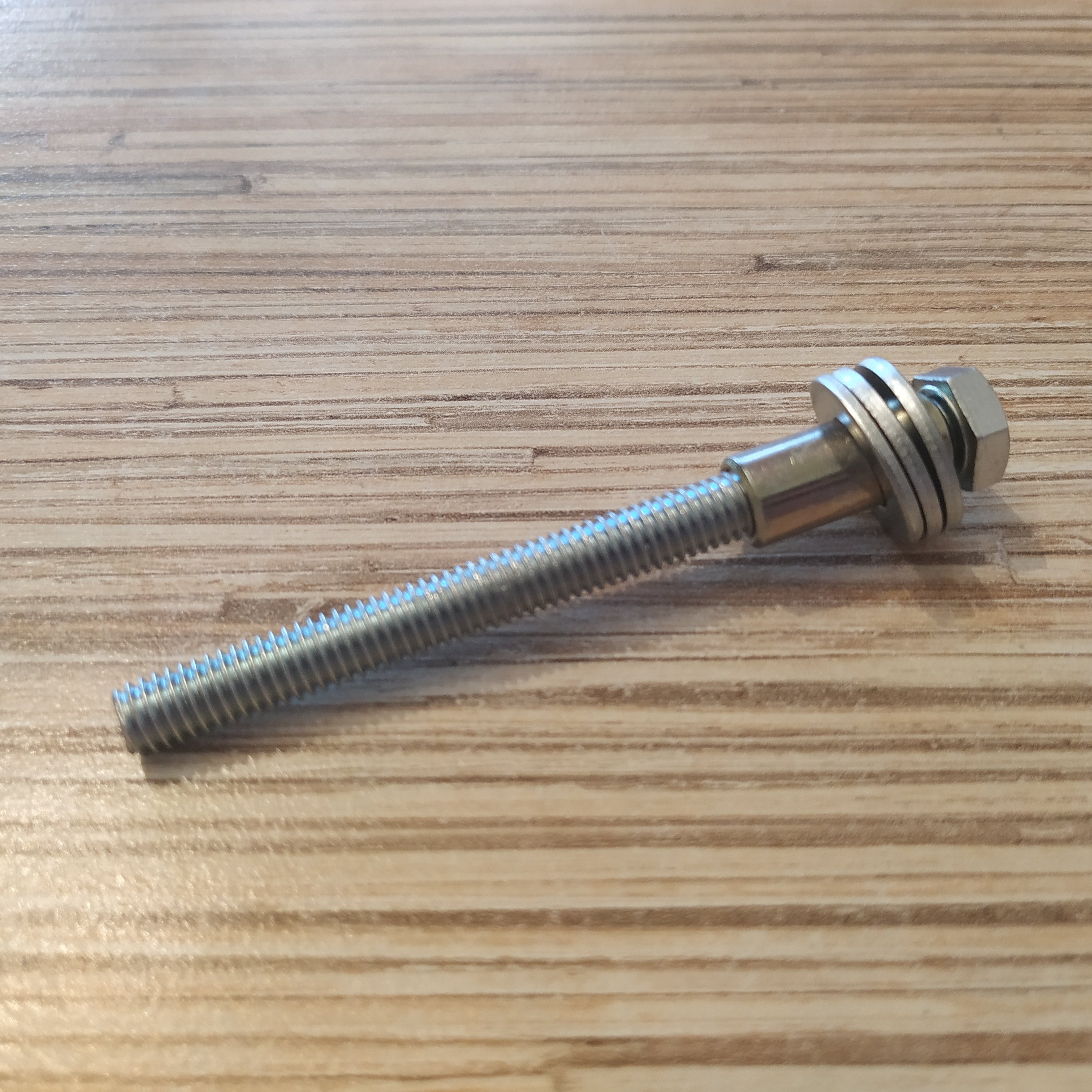
8. Put 2 bearings onto the hub
9. Put a reinforced M6 nut onto the bolt
10. Put an axis though the lever connector part
11. Put a reinforced nut onto the M6 bolt.