Table of Contents
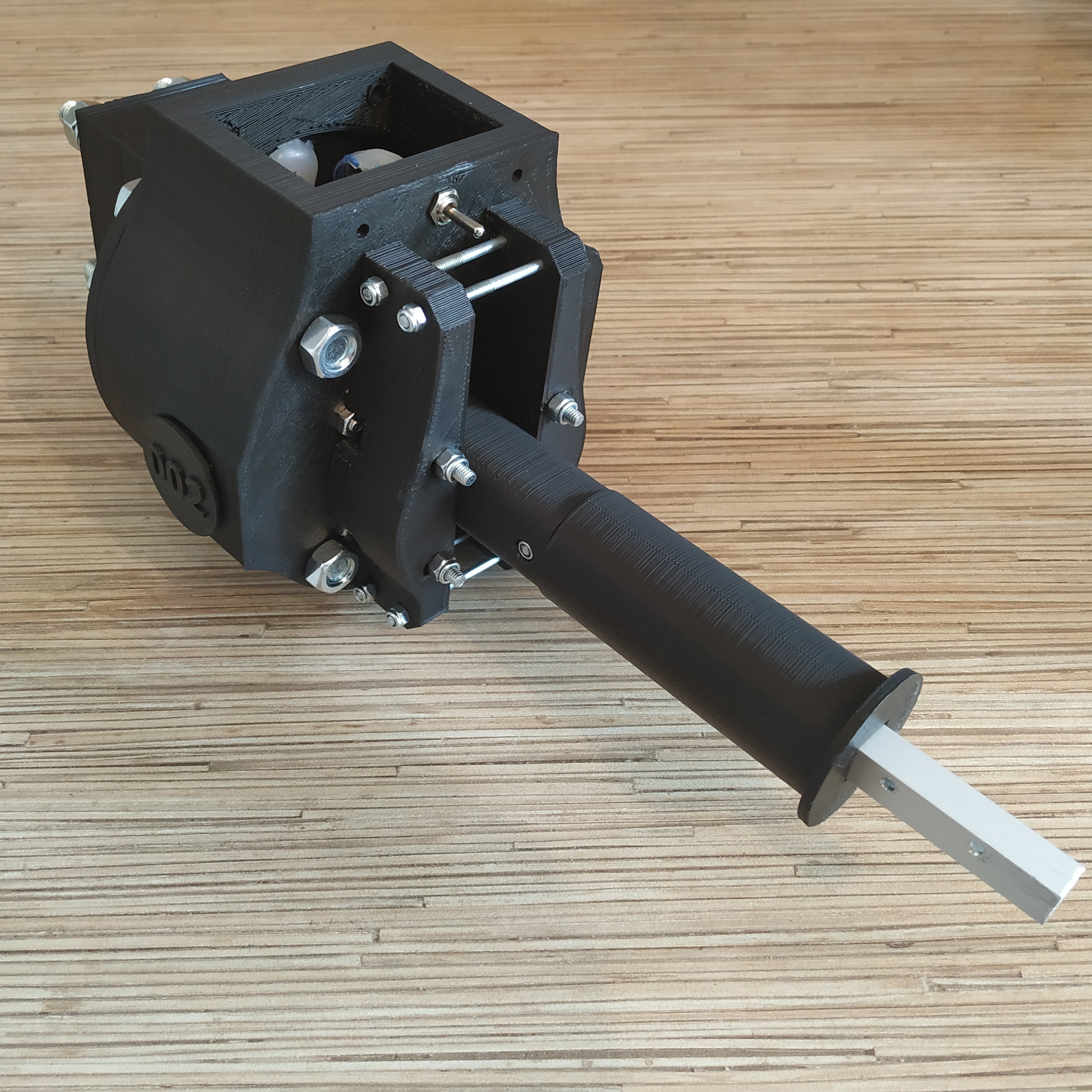
Simchair MKIV collective lever base
Components
- 1 x 10x10mm aluminum square pipe
- 1 x 20×10 aluminum rectangular pipe
- 1 x SS495A1 hall sensor
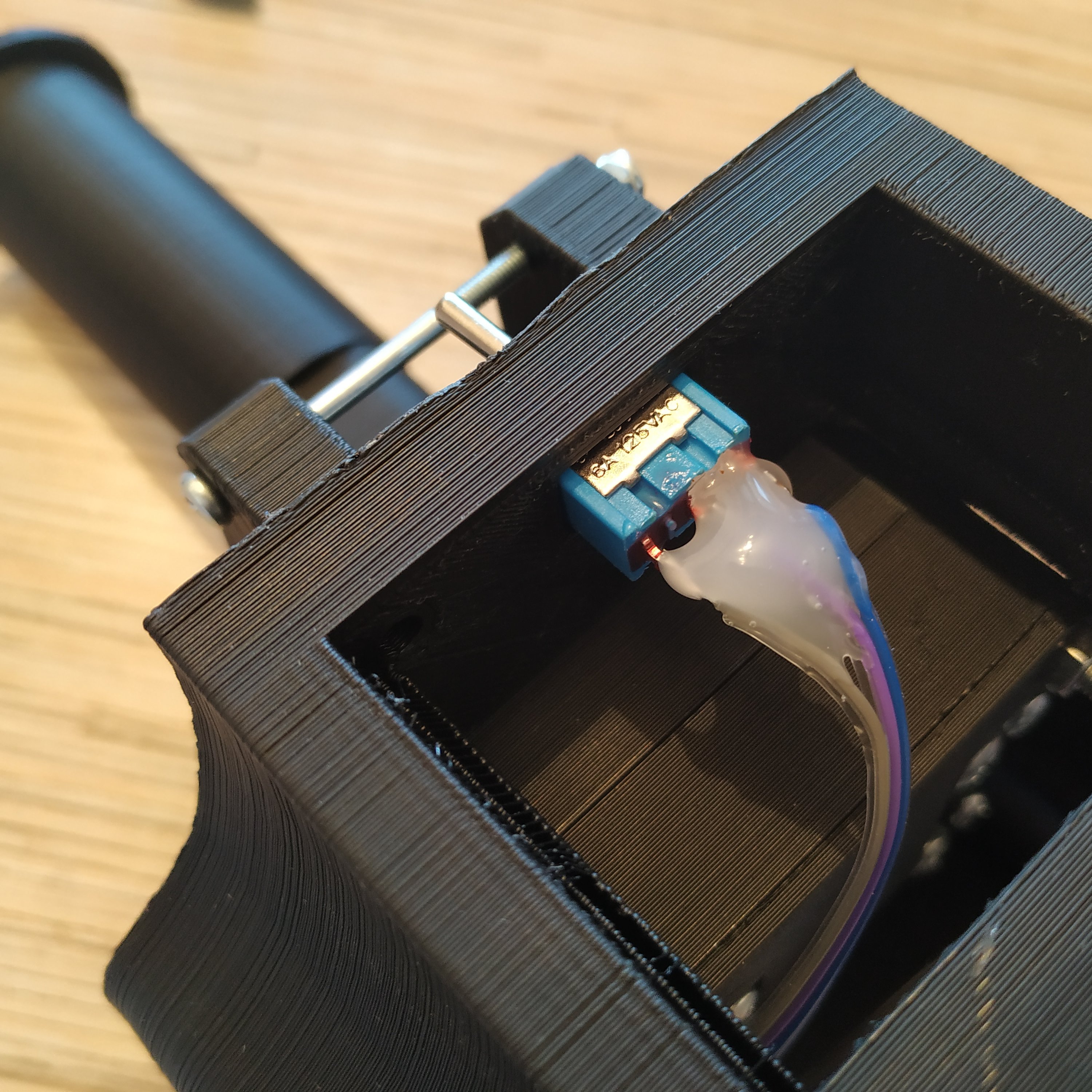
- 1 x MTS-103 ON-OFF-ON switch
- 1 x 16K1 10KOhm LINEAR rotary potentiometer
- 1 x 6x6x4mm square magnet
- 1 x M6x70mm screw
- 2 x M6 washers (reinforced)
- 1 x M6 nut
- 2 x M6x18x8mm hubs
- 6 x M4x40mm screws
- 4 x M4x70mm screws
- 1 x M3x20mm screw
- 1 x M3 nyloc nut
- 4 x M4 nyloc nuts
- 4 x M3x50mm screws for tensioner halves contraction
- 4 x M8x70 bolts
- 4 x M8x75mm bolts
- 8 x M8 nuts
- 10 x M8 washers (regular, non-reinforced)
- 4 x M8 spring washers
- 1 x bag of M4 nuts
- 4 x 608 bearings (standard skateboard bearings)
- 1 x Arduino Pro mini
- 1 x Simchair MKIV Master controller
- super glue (cyanoacrylate), hot glue gun
Files location in repos
simchair4_models\printable components\peripherals\helicopter\collective lever\a_base - models
simchair4_software\peripherals - choose the preferred variant of the lever - software
Assembling manual
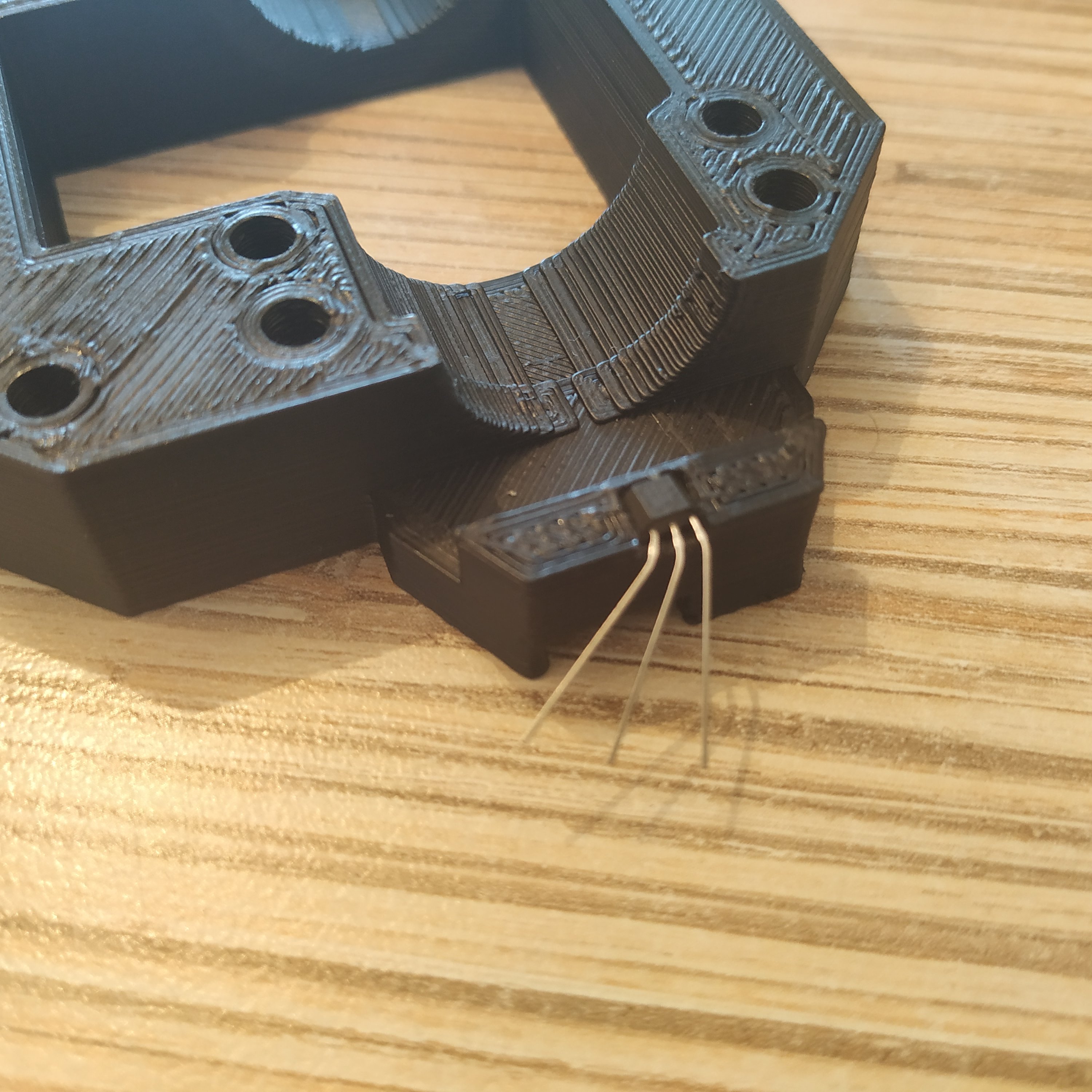
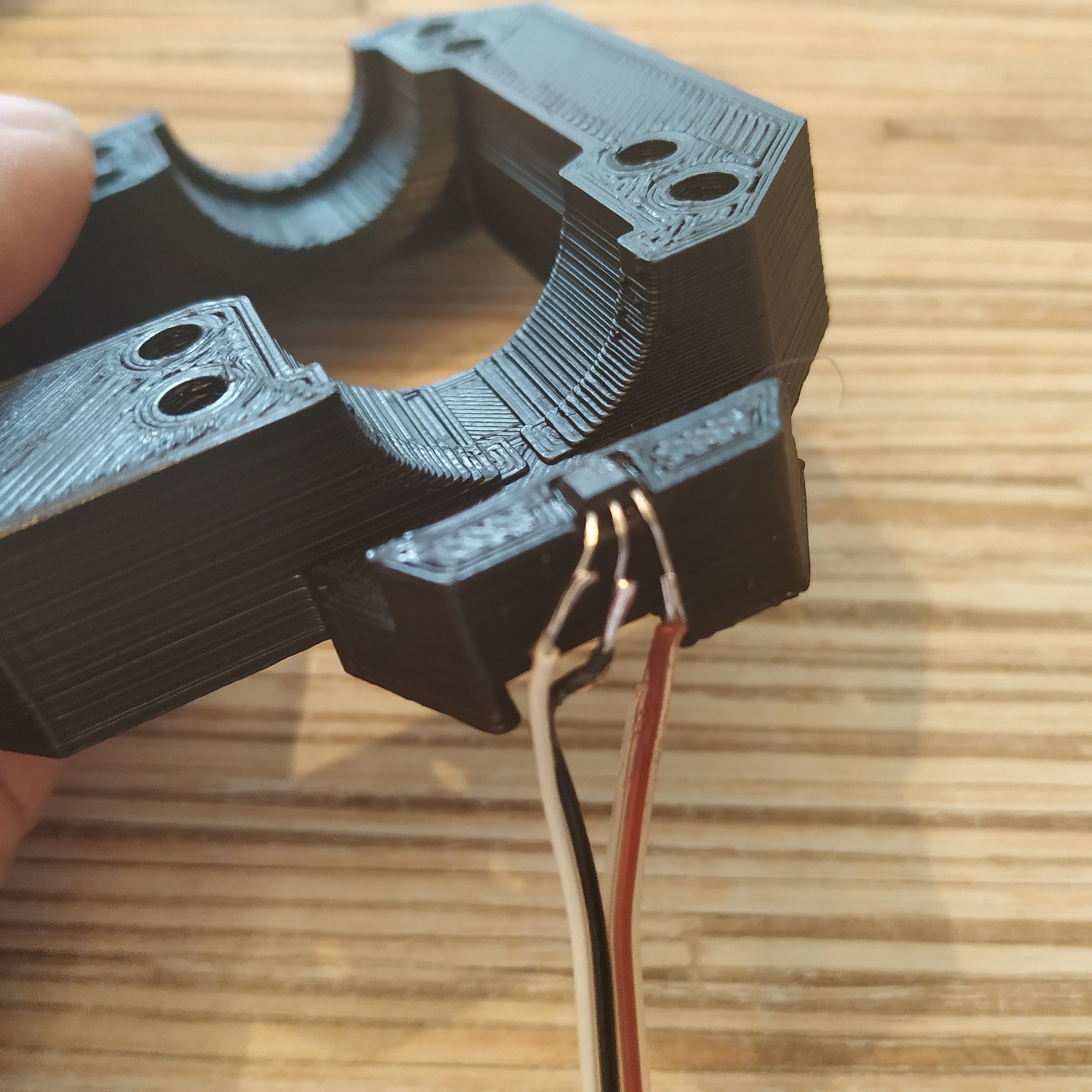
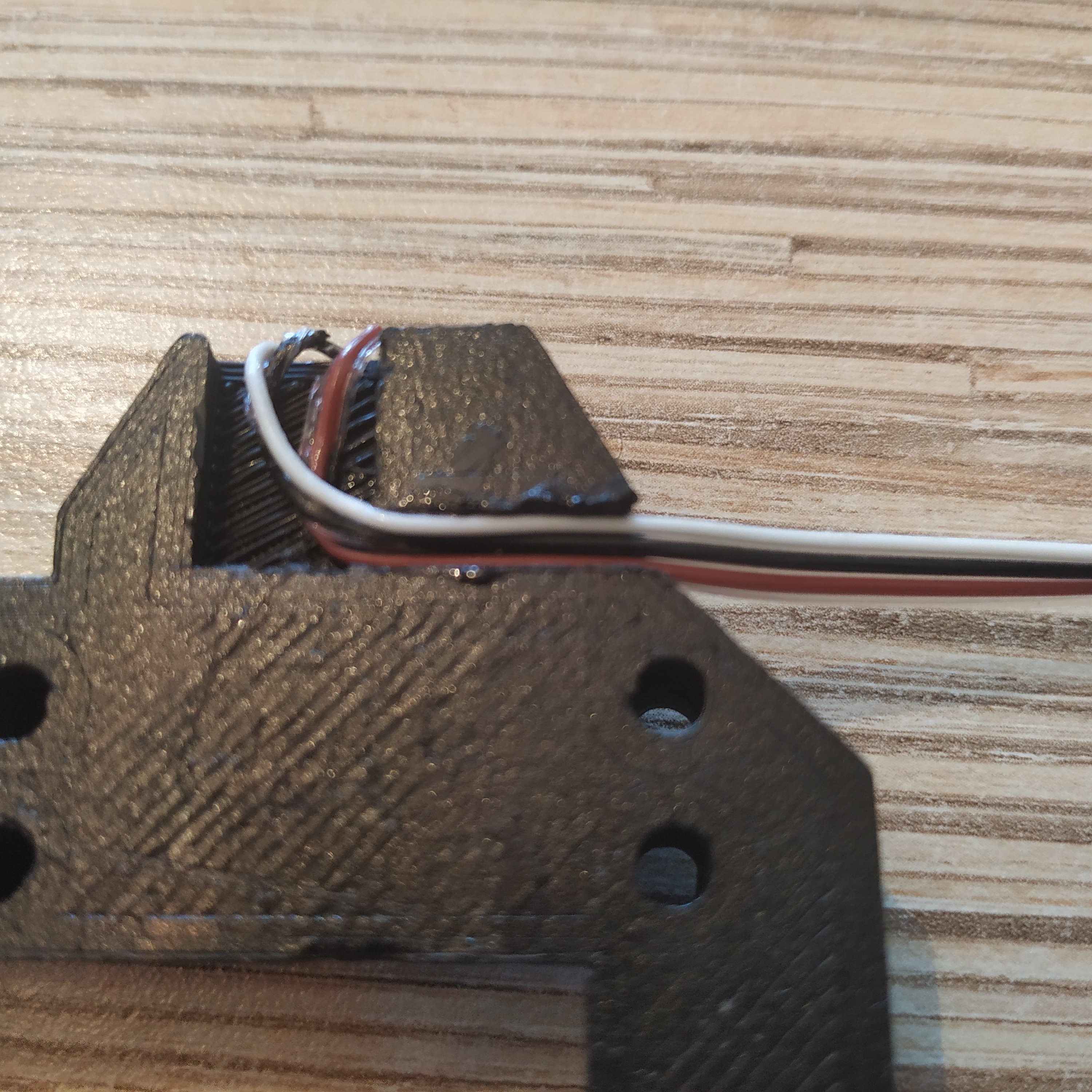
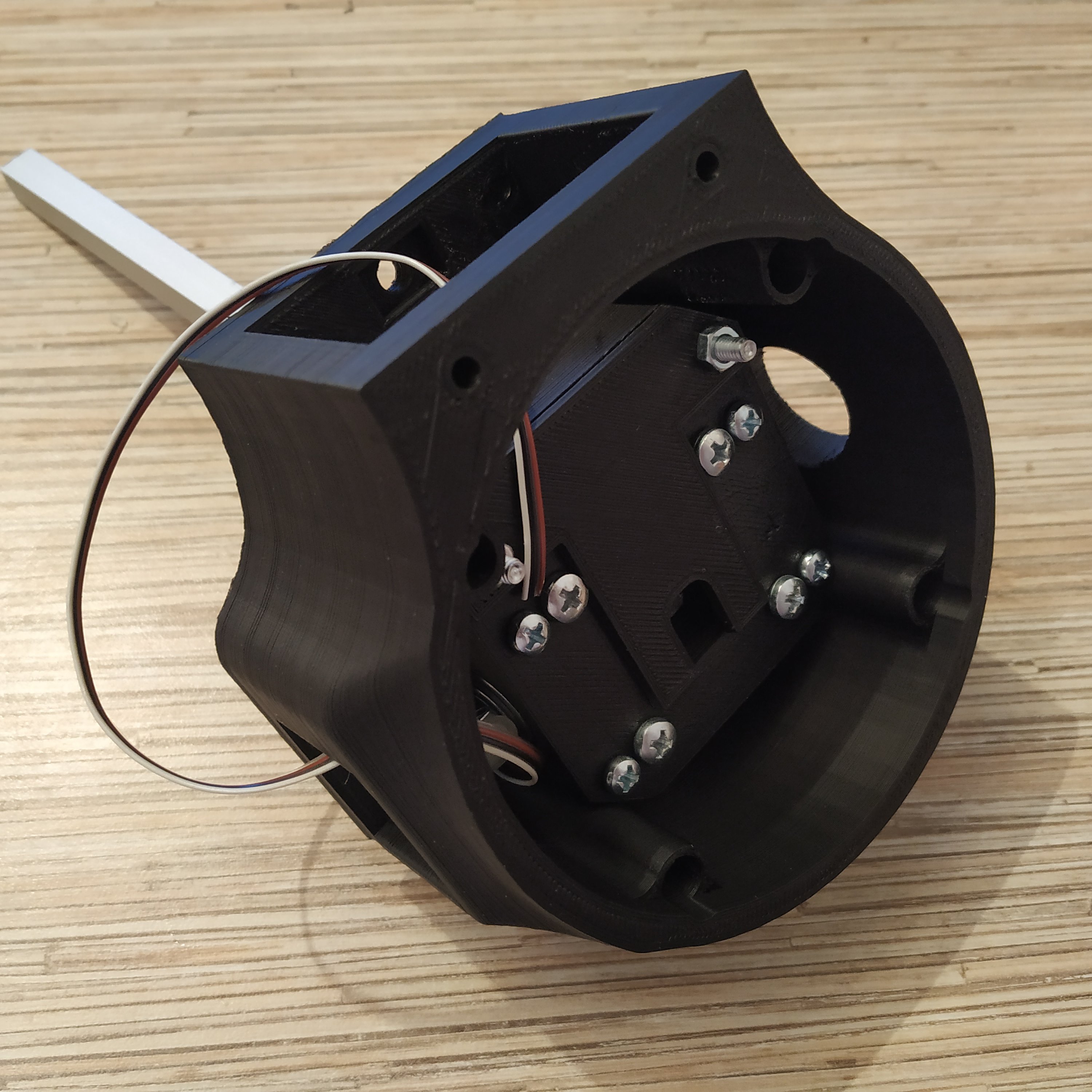
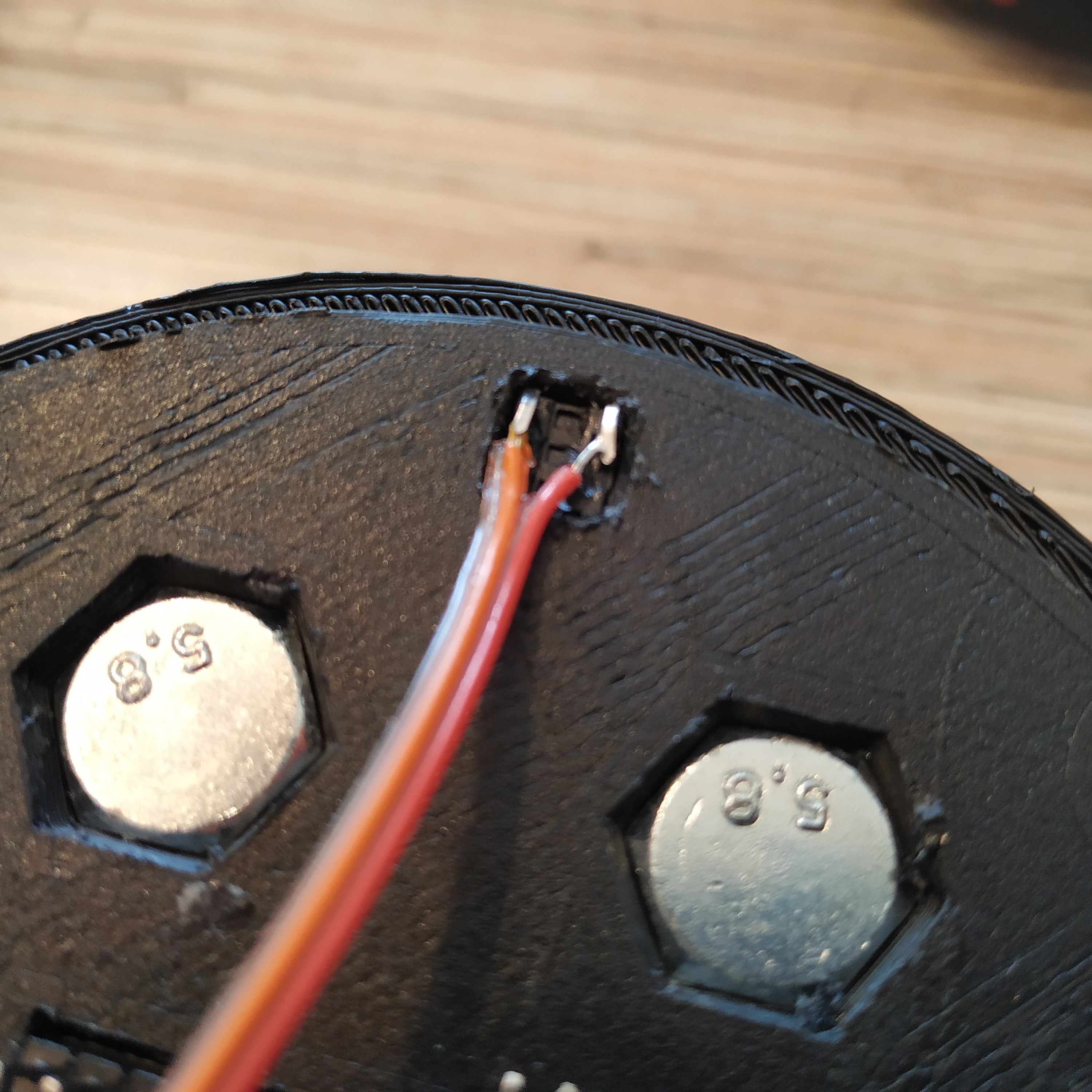
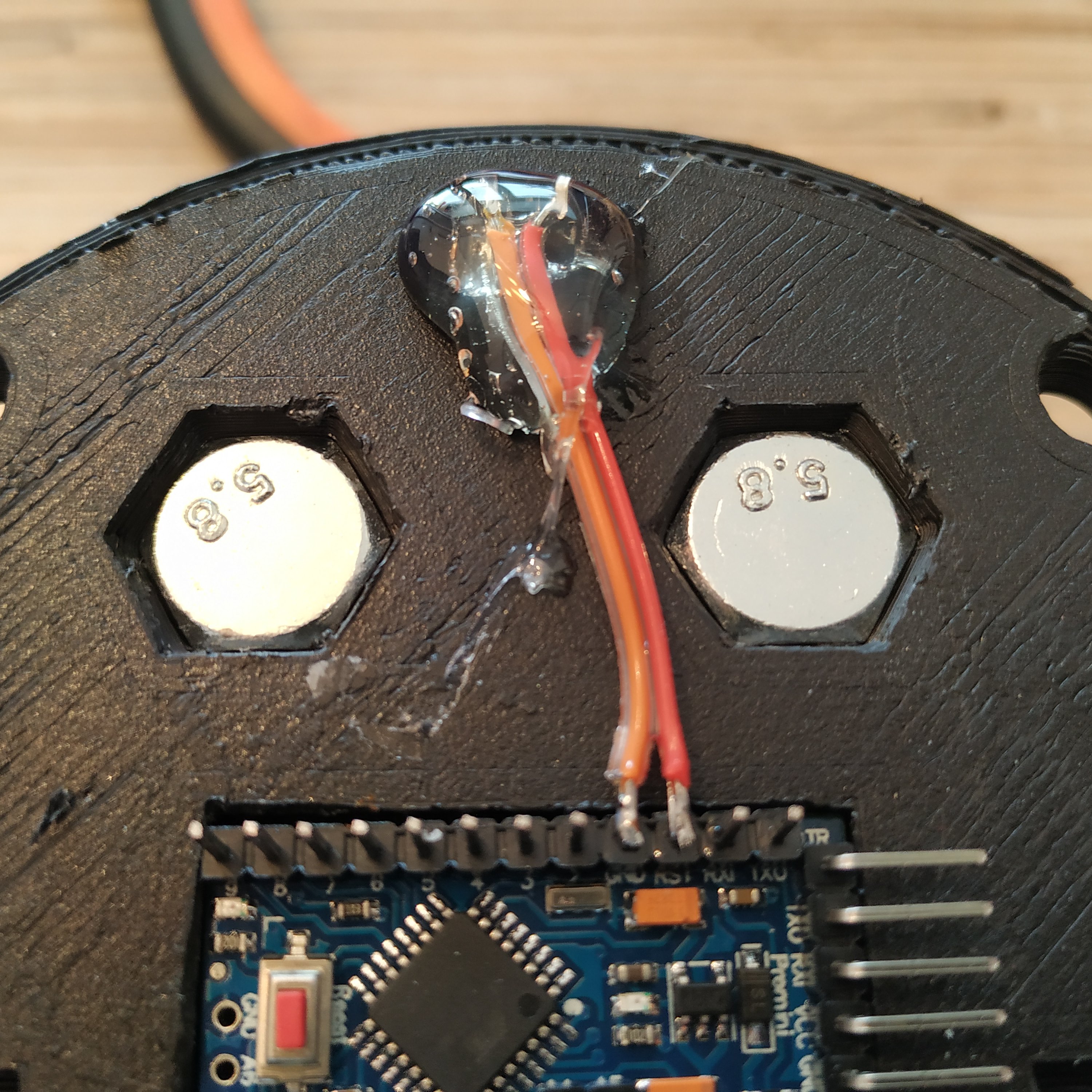
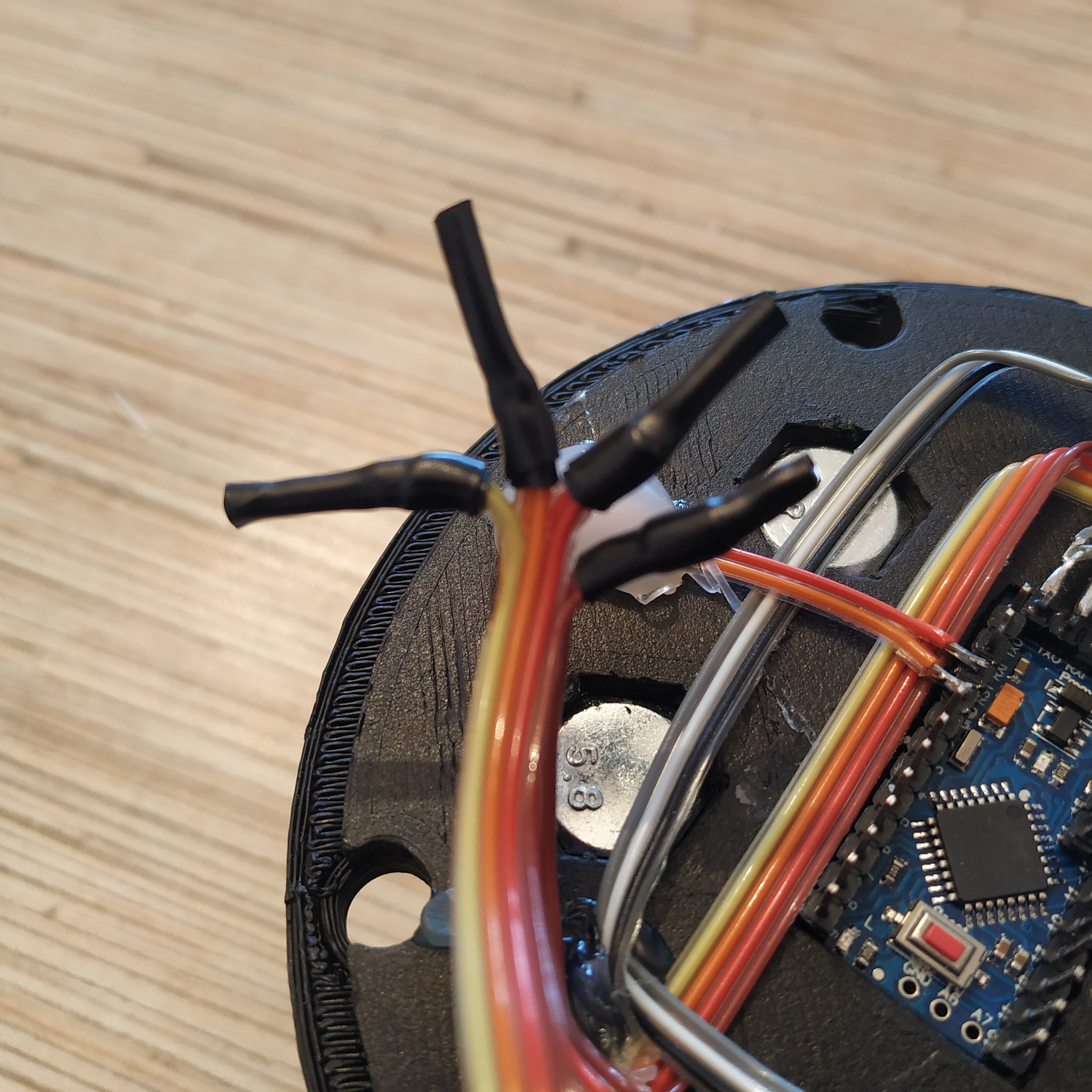
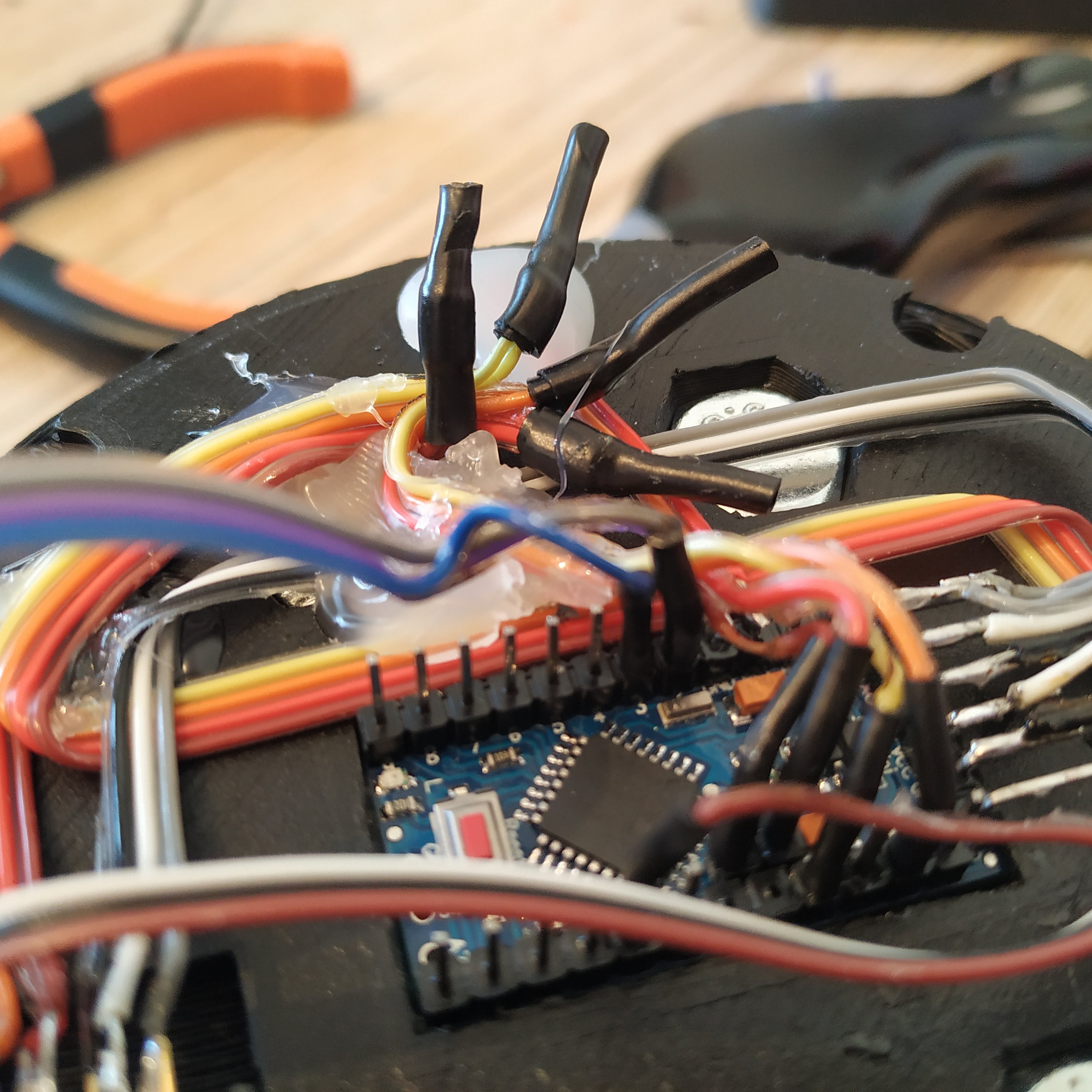
1. Insert SS495A1 into its socket in the top part of the lever frame (use a drop of super glue to fix it there) and solder its wires. Route wires as shown on the 3rd picture, use some glue as necessary.
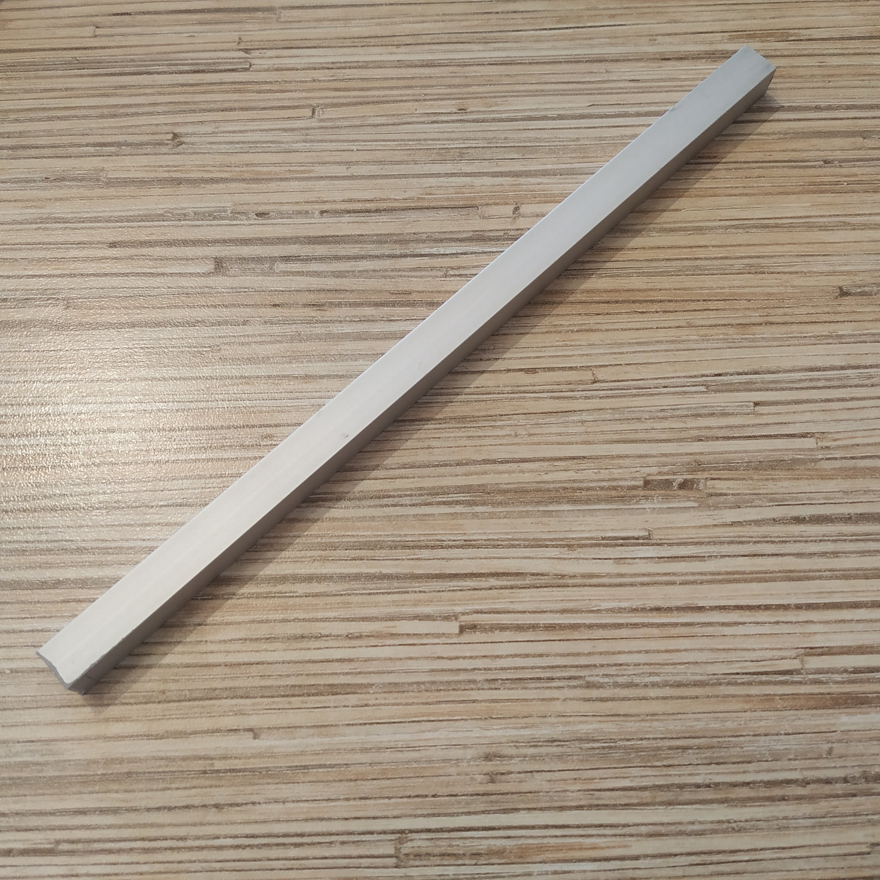
2. Cut off a piece of 10mm square aluminum profile. Choose the length depending on the lever you want to build (as stated in the lever body manual, e.g. 200mm for a single throttle lever)
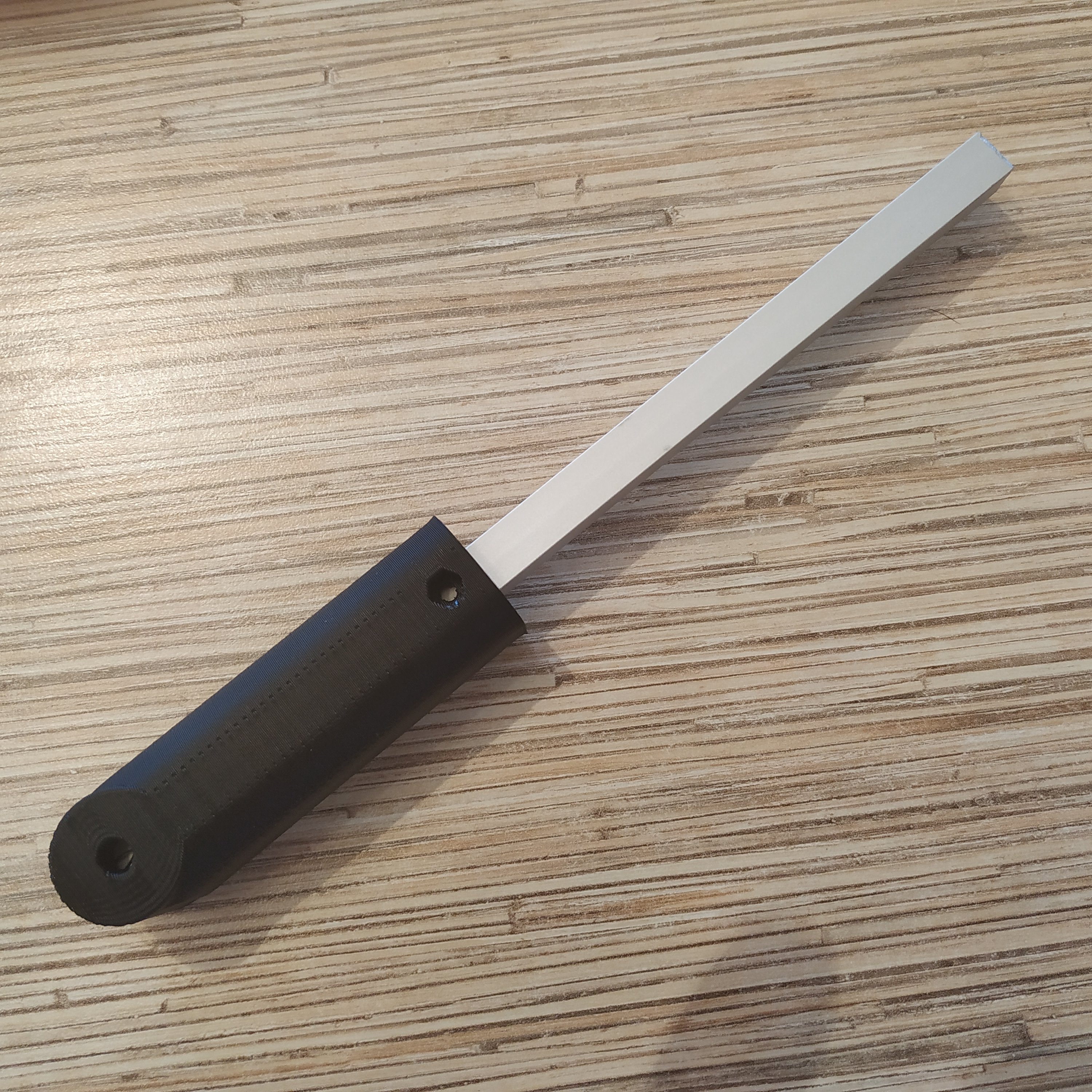
3. Put the lever connector part onto the rail.
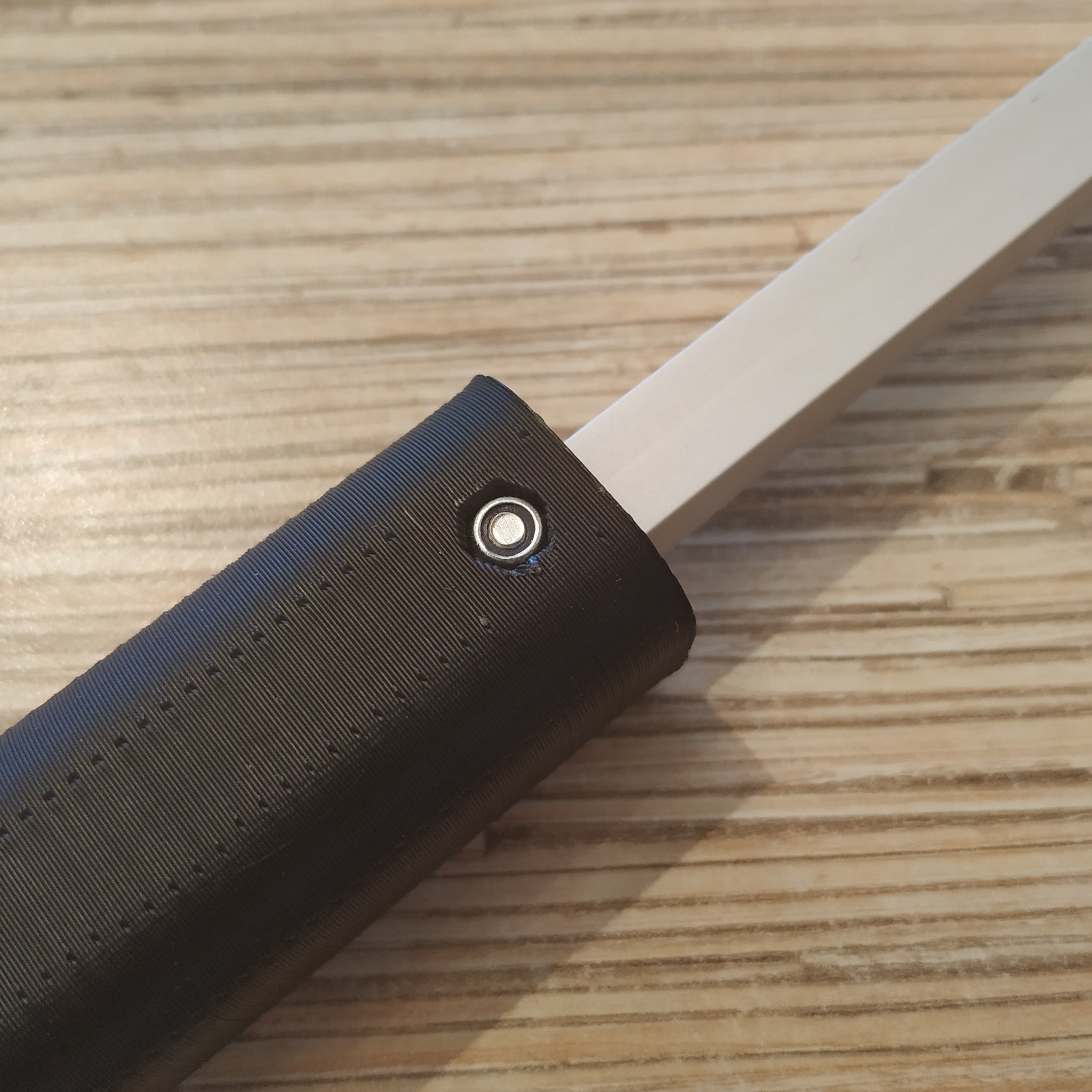
4. Drill a 3mm hole through the rail and insert an M3x20mm screw with a nyloc nut.
5. Drill a 6mm hole for the axis through the rail with a 5,5mm drill.
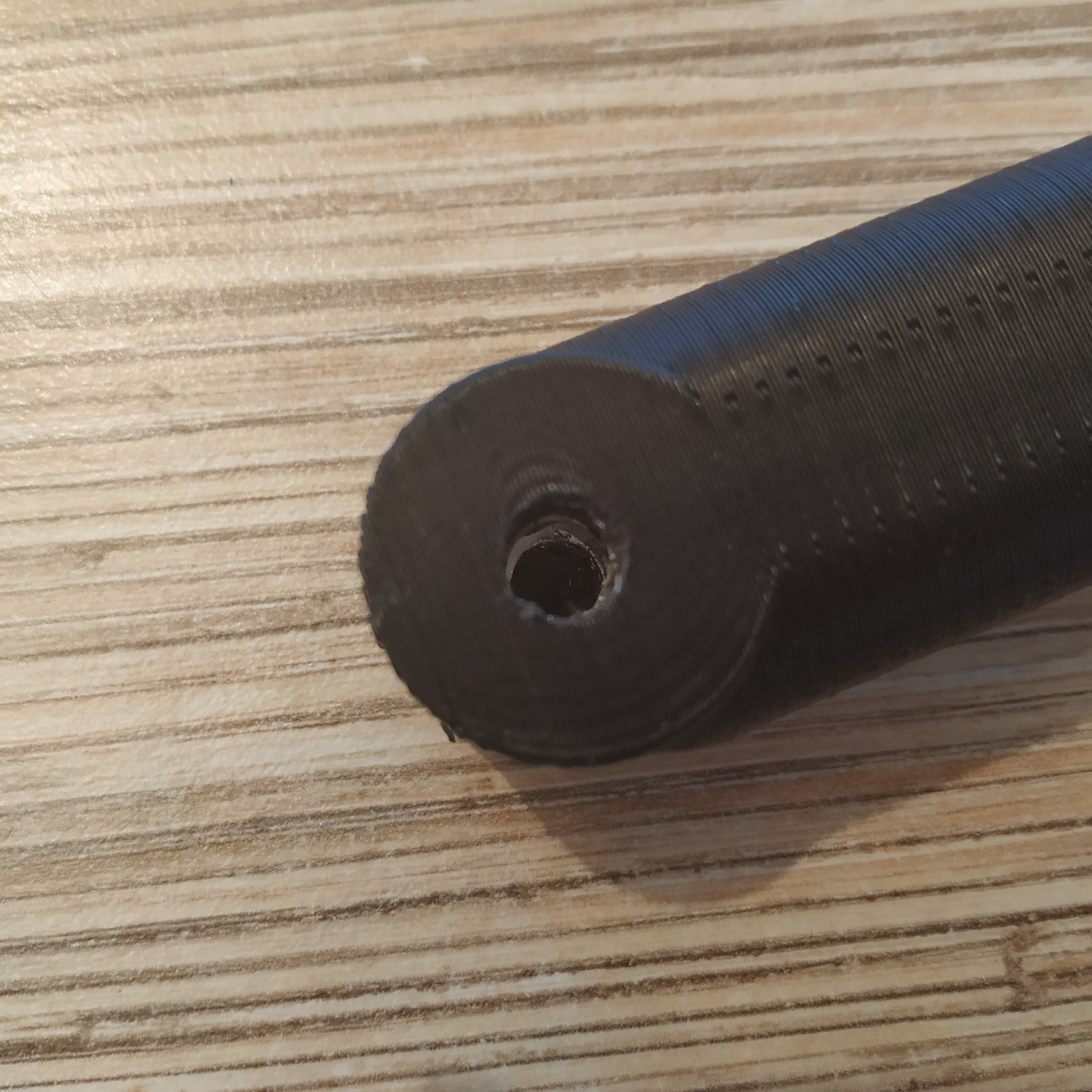
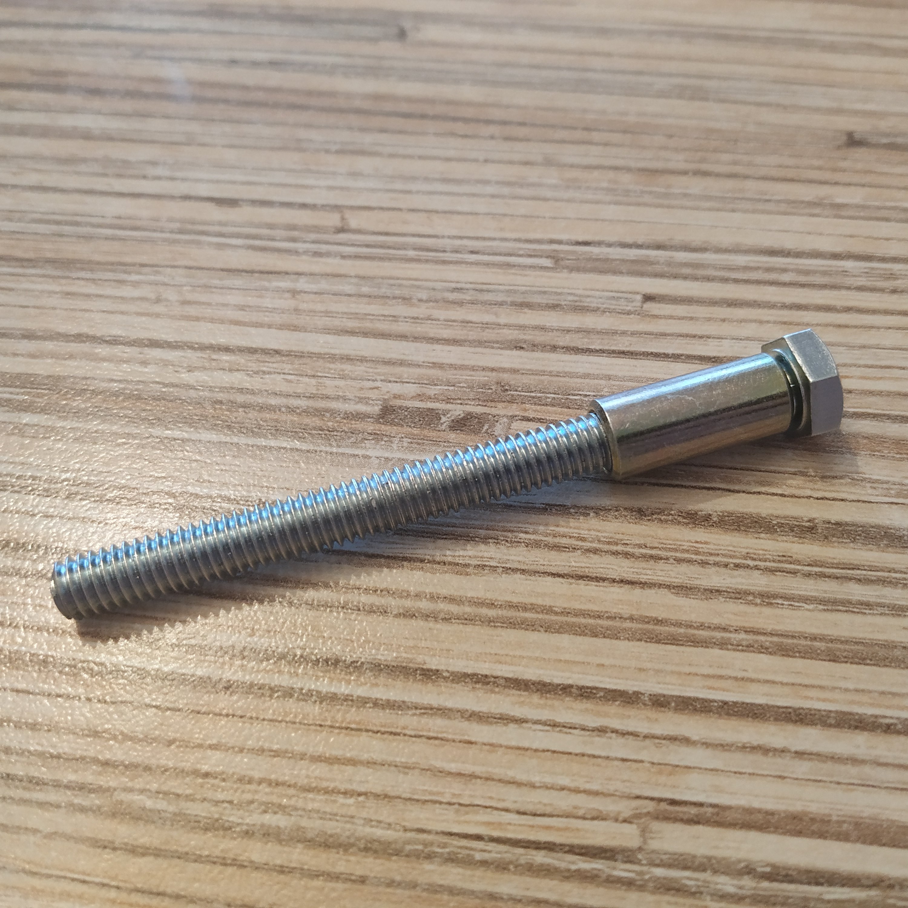
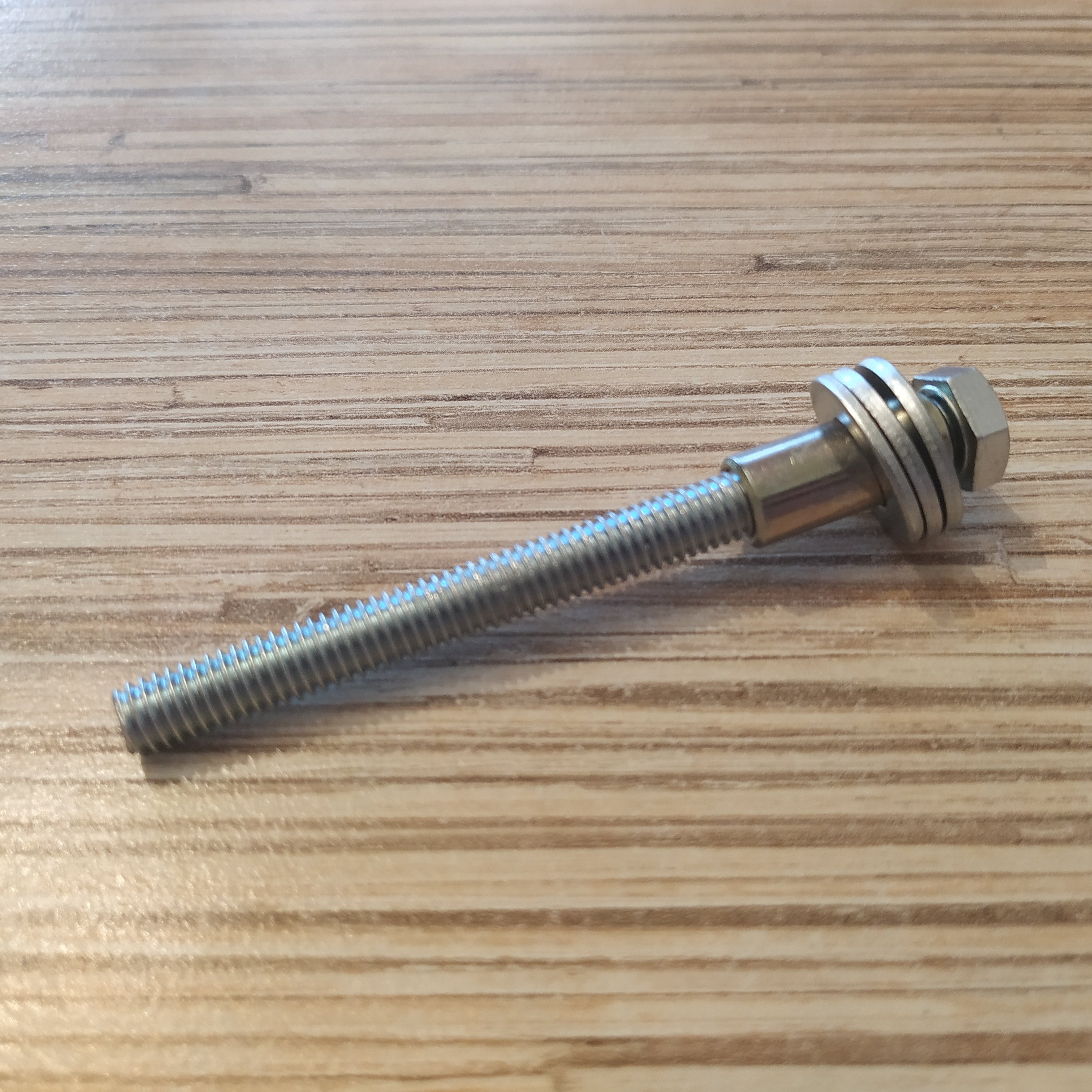
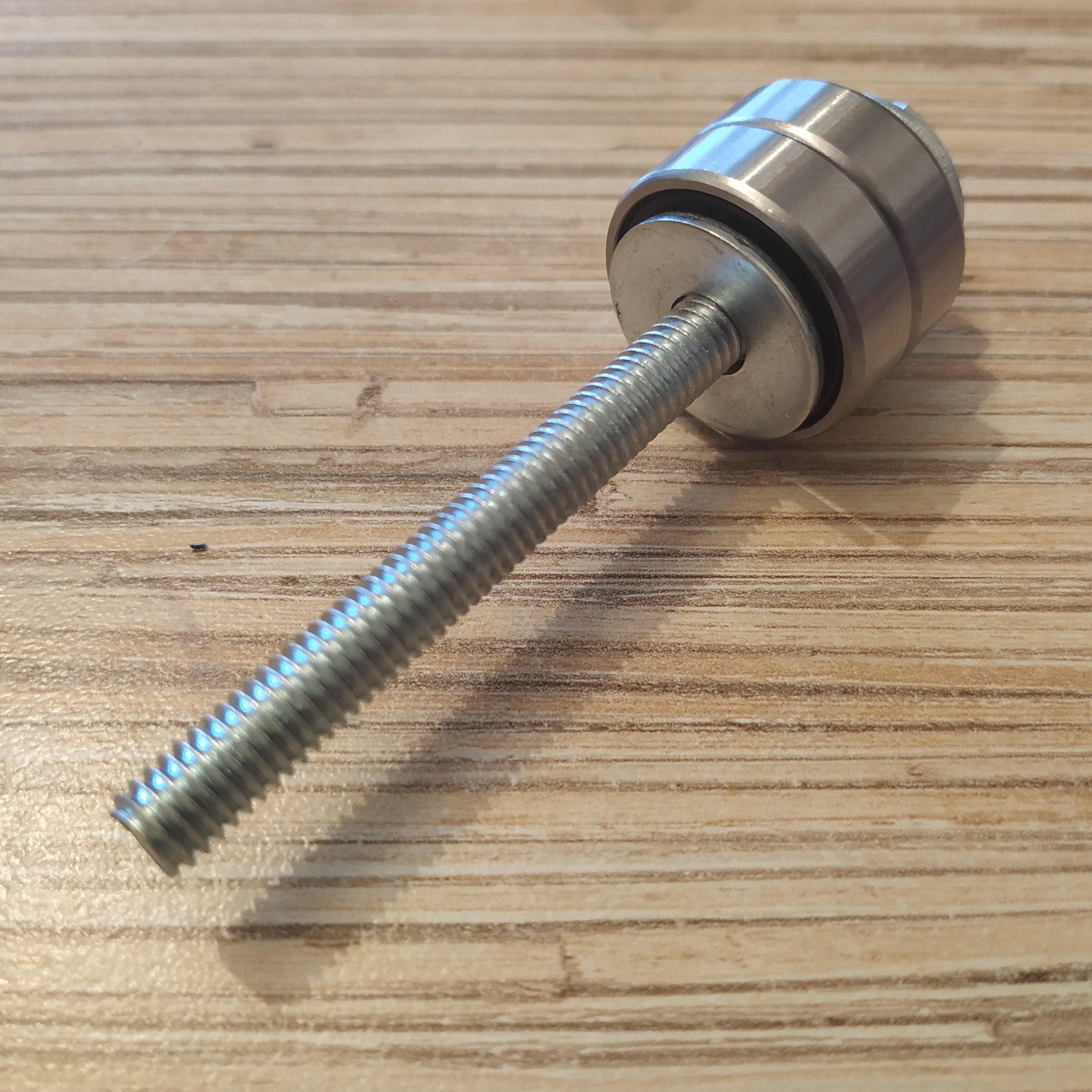
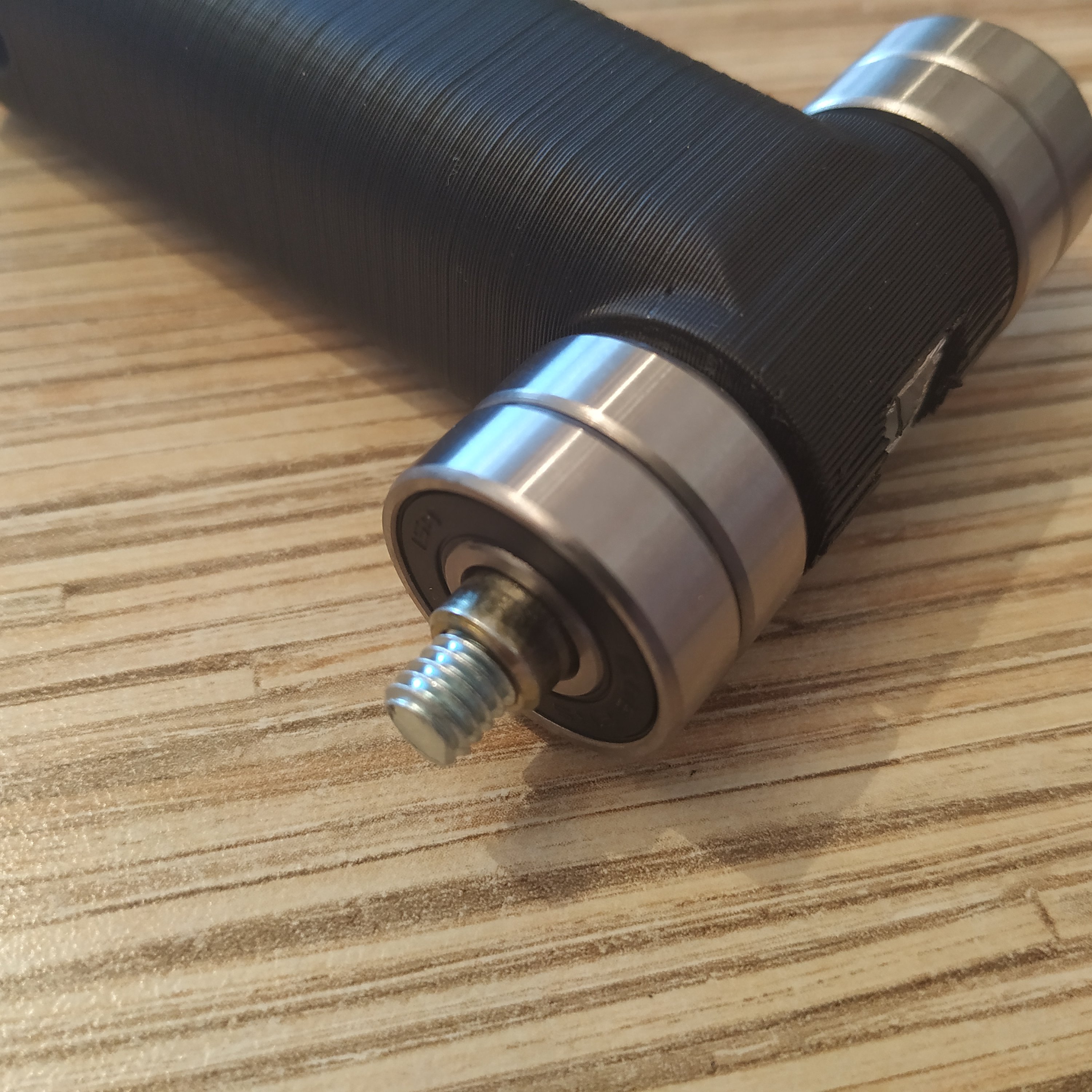
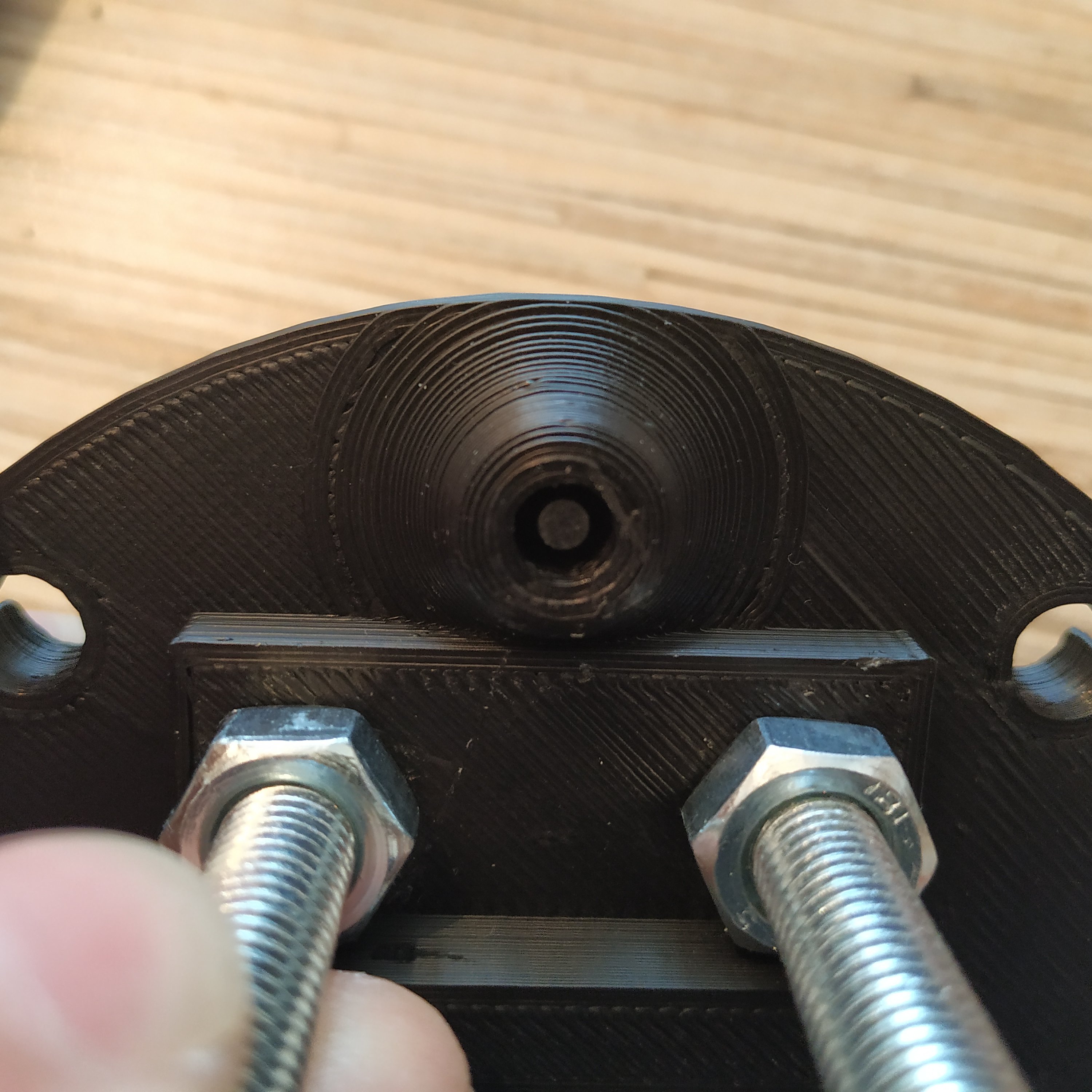
6. We will be assembling the lever axis. Start with putting an M6x8x18mm hub onto an M6x70mm bolt.
7. Put 3 M8 washers onto the hub
8. Put 2 bearings onto the hub
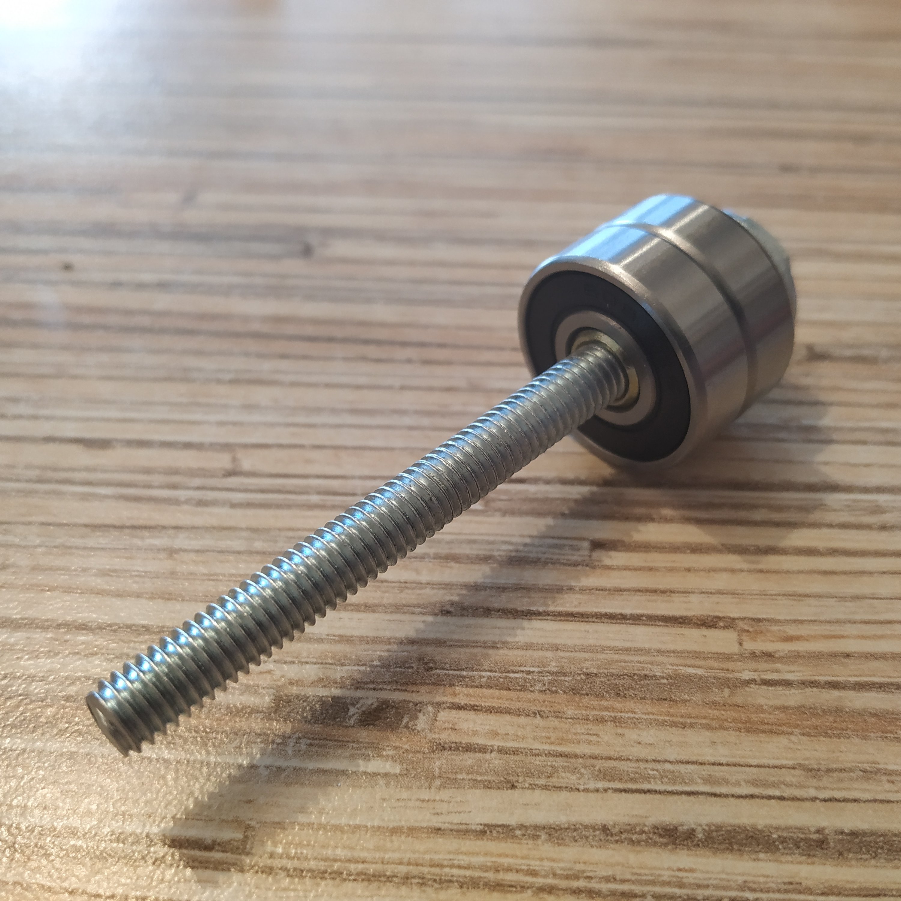
9. Put a reinforced M6 nut onto the bolt
10. Put an axis though the lever connector part
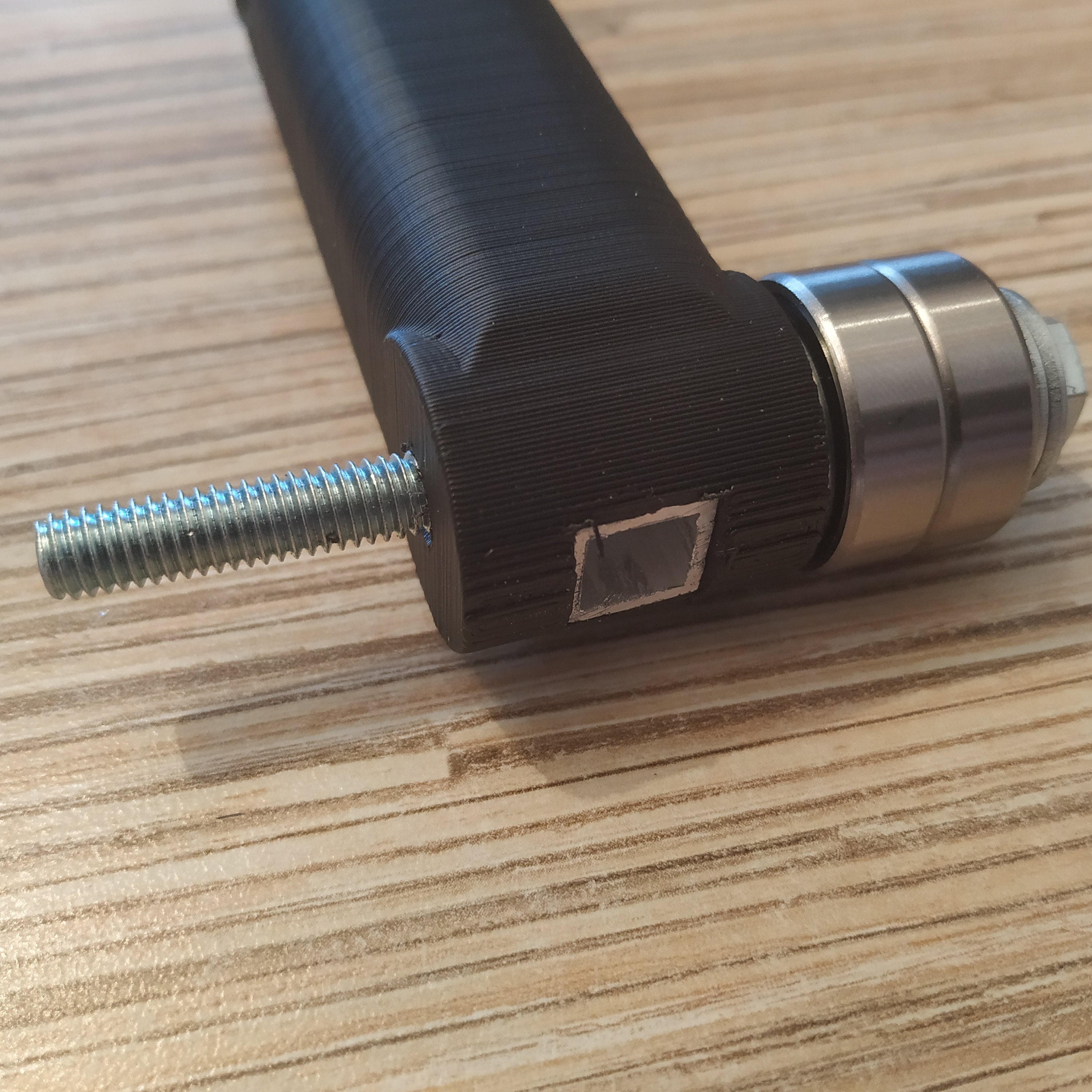
11. Put a reinforced nut onto the M6 bolt.
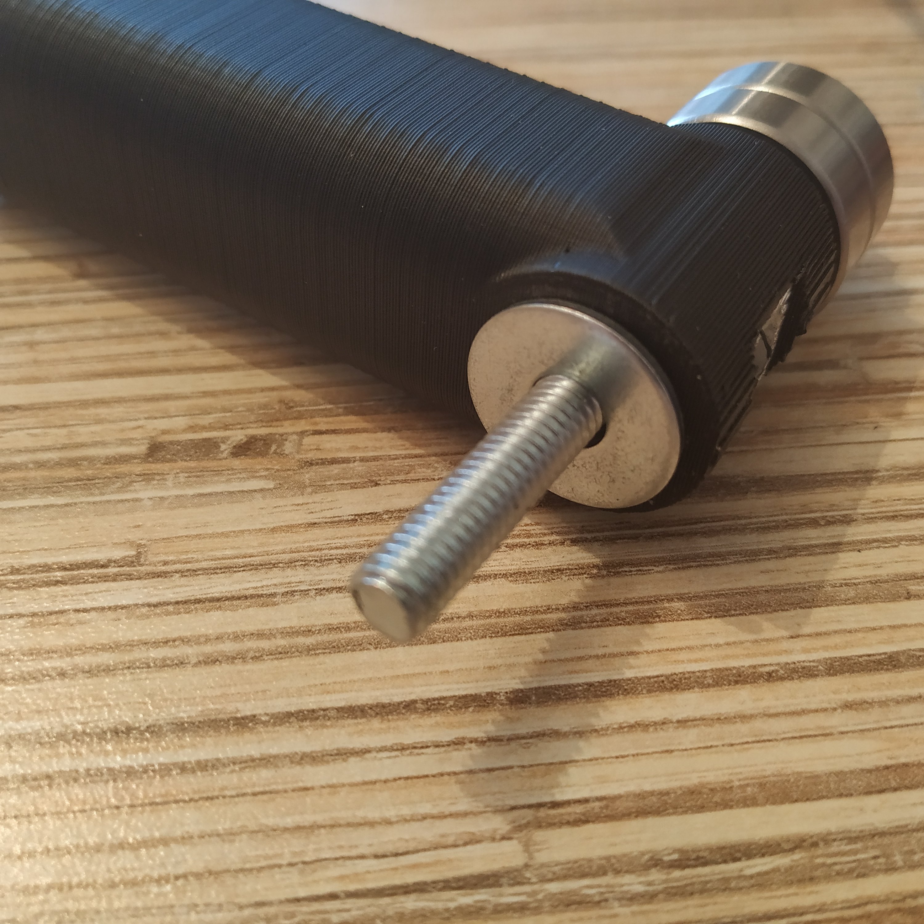
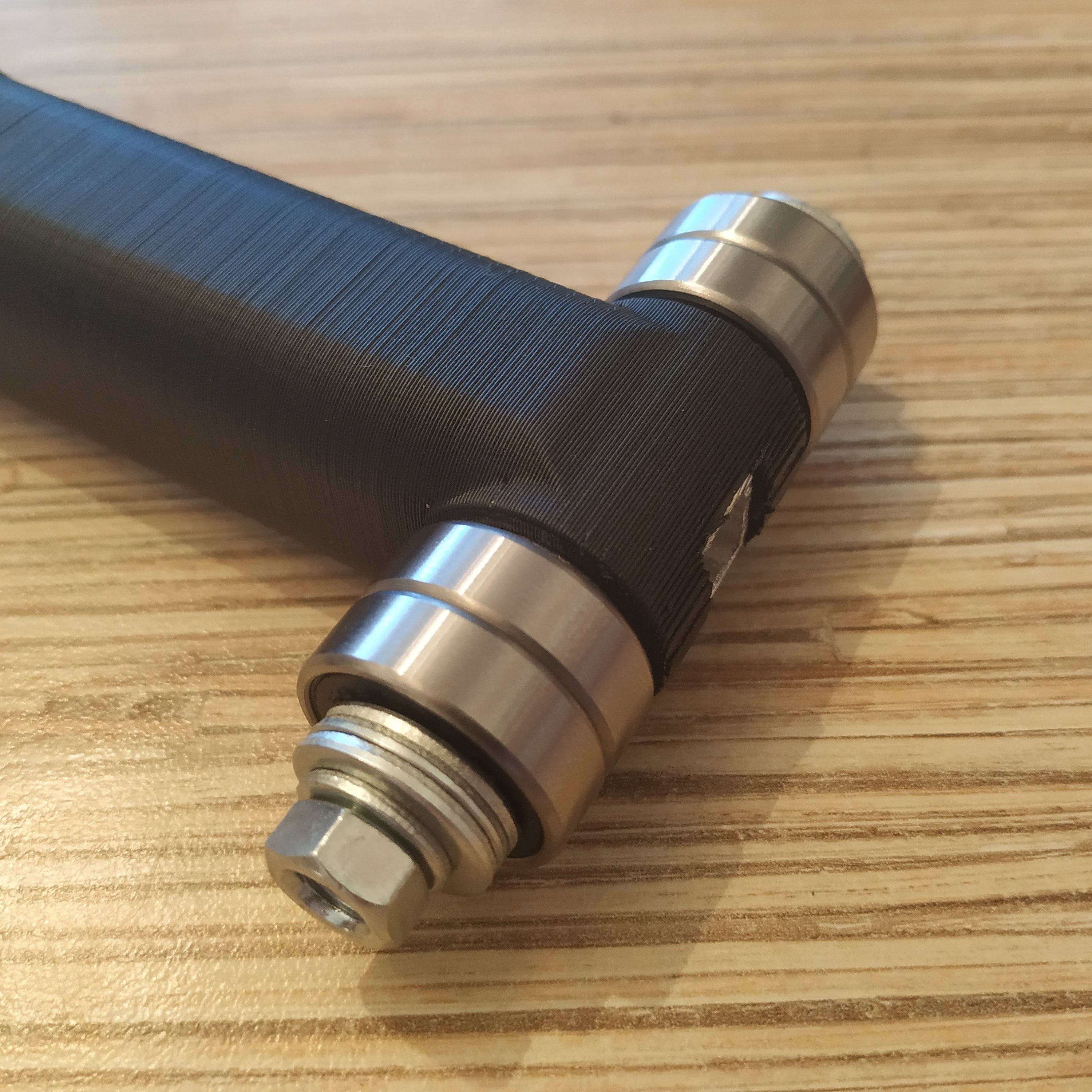
12. Put another hub onto the bolt.
13. Put 2 bearings onto the hub
14. Add 3 M8 washers
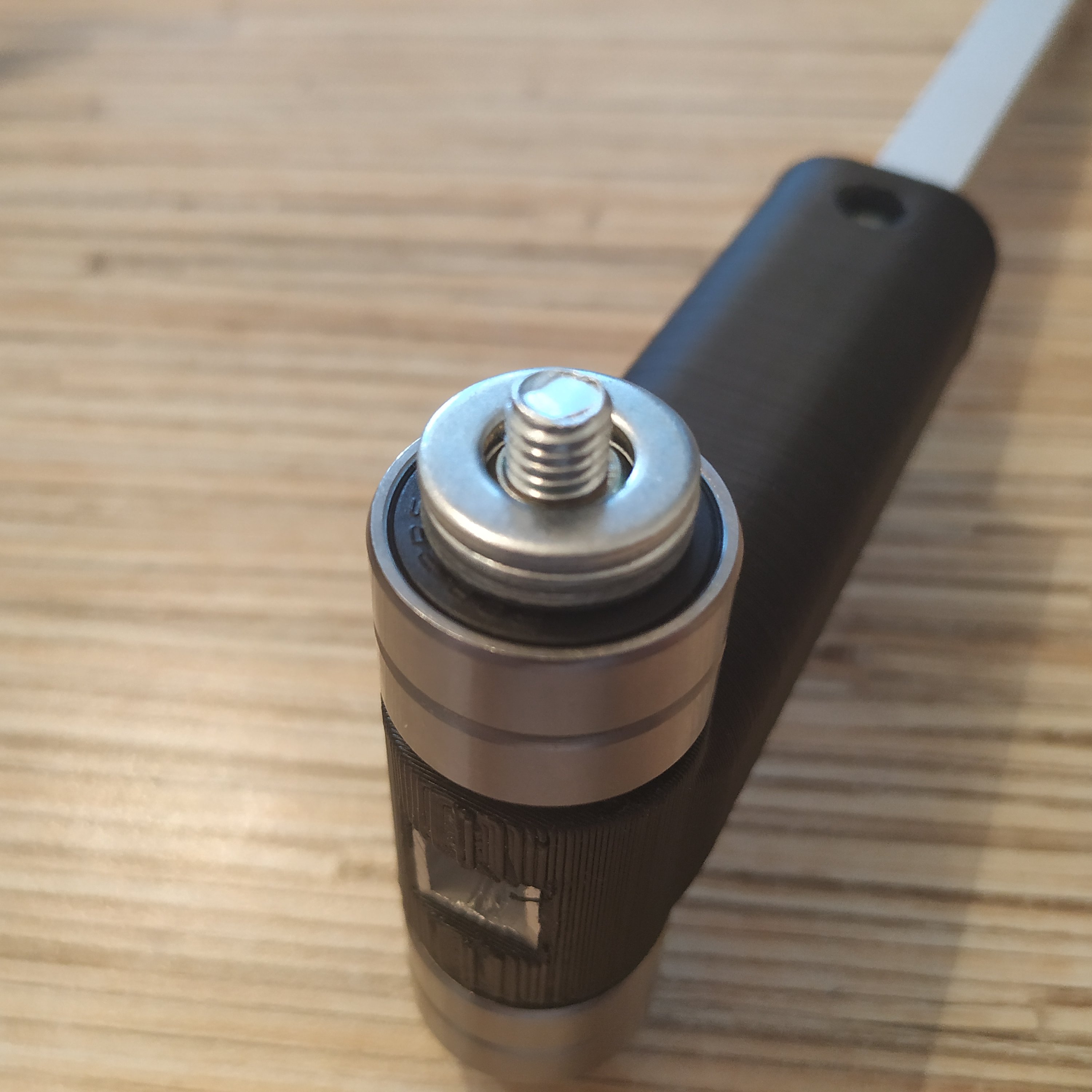
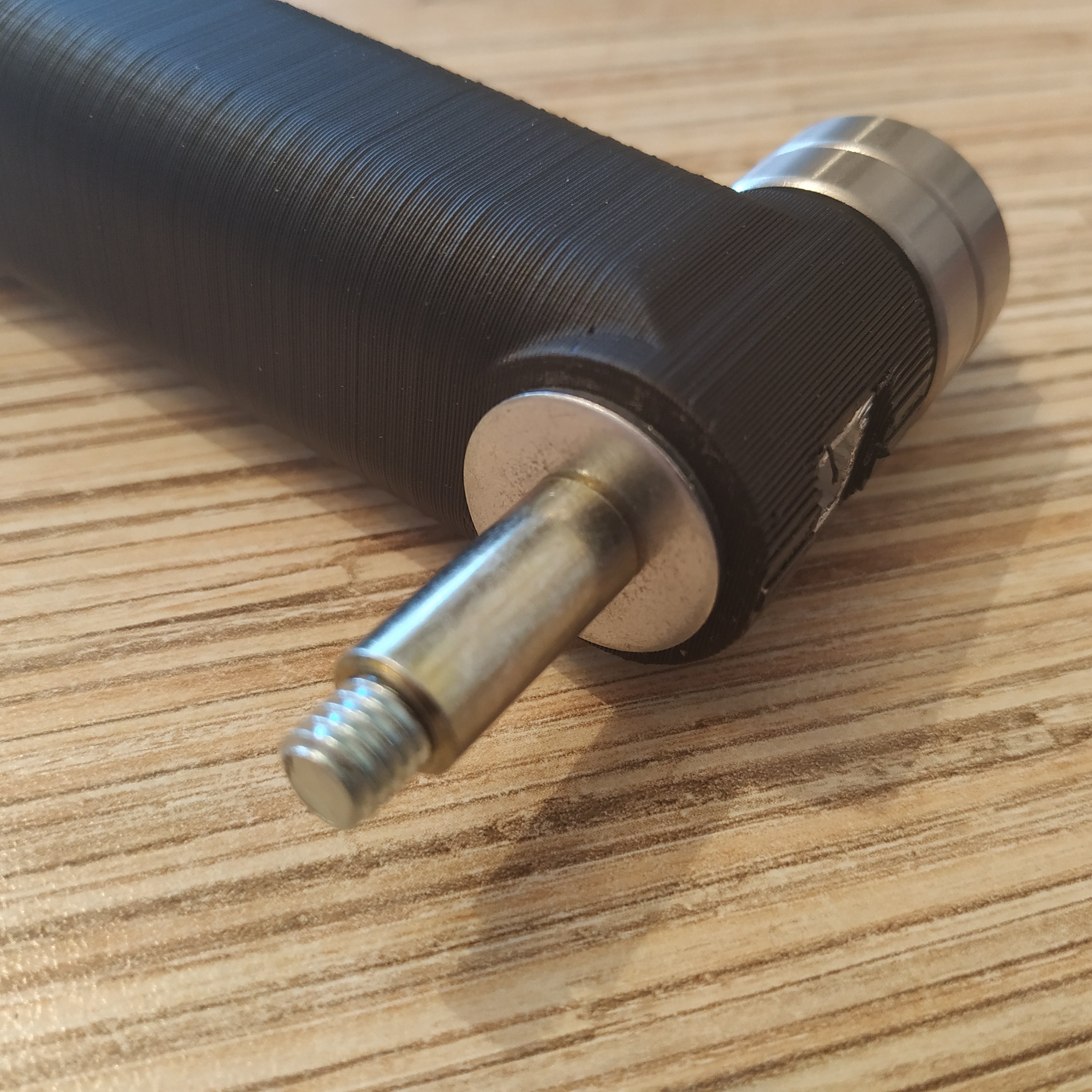
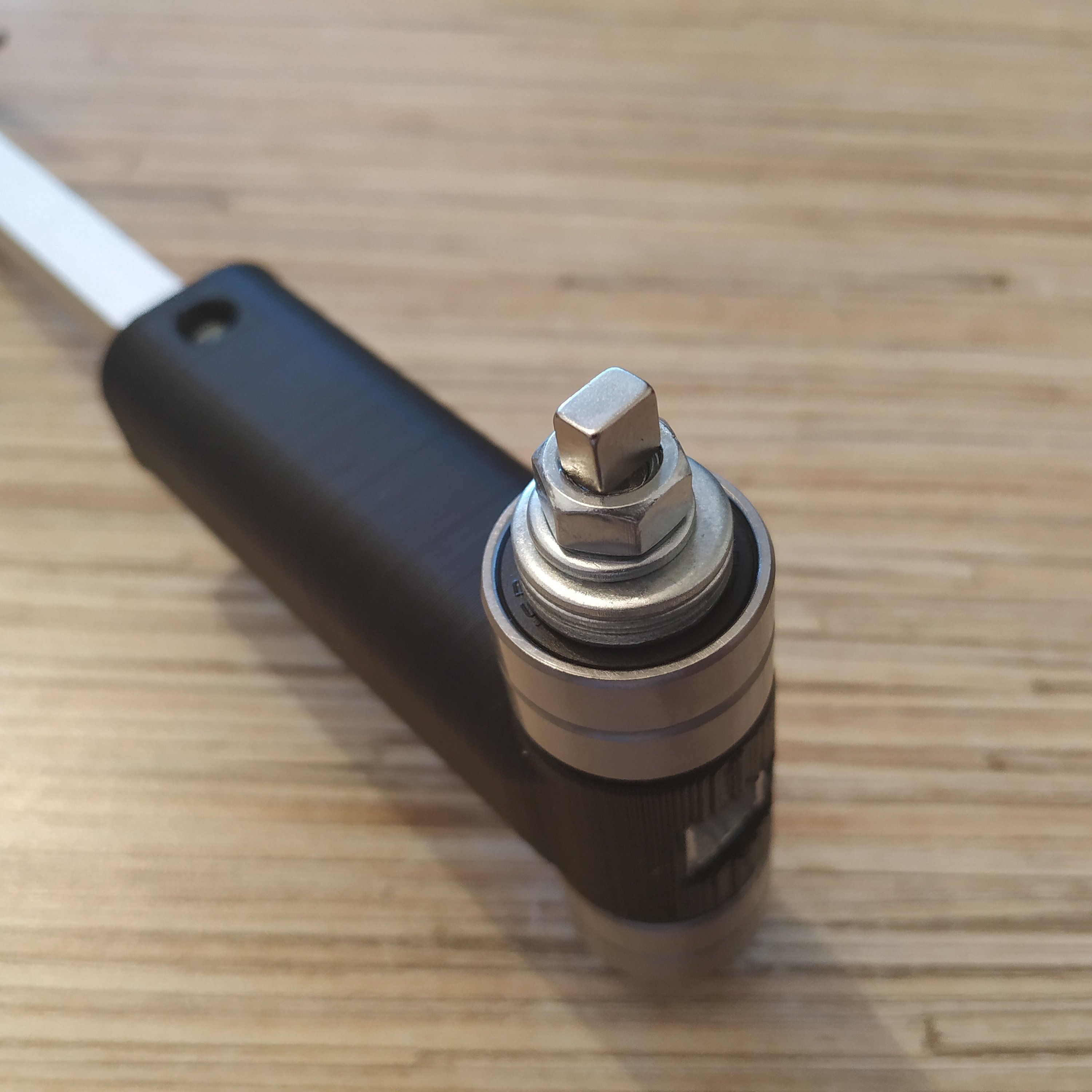
15. Put an M6 washer and a nut onto the bolt. Use thread locker to fix the nut.
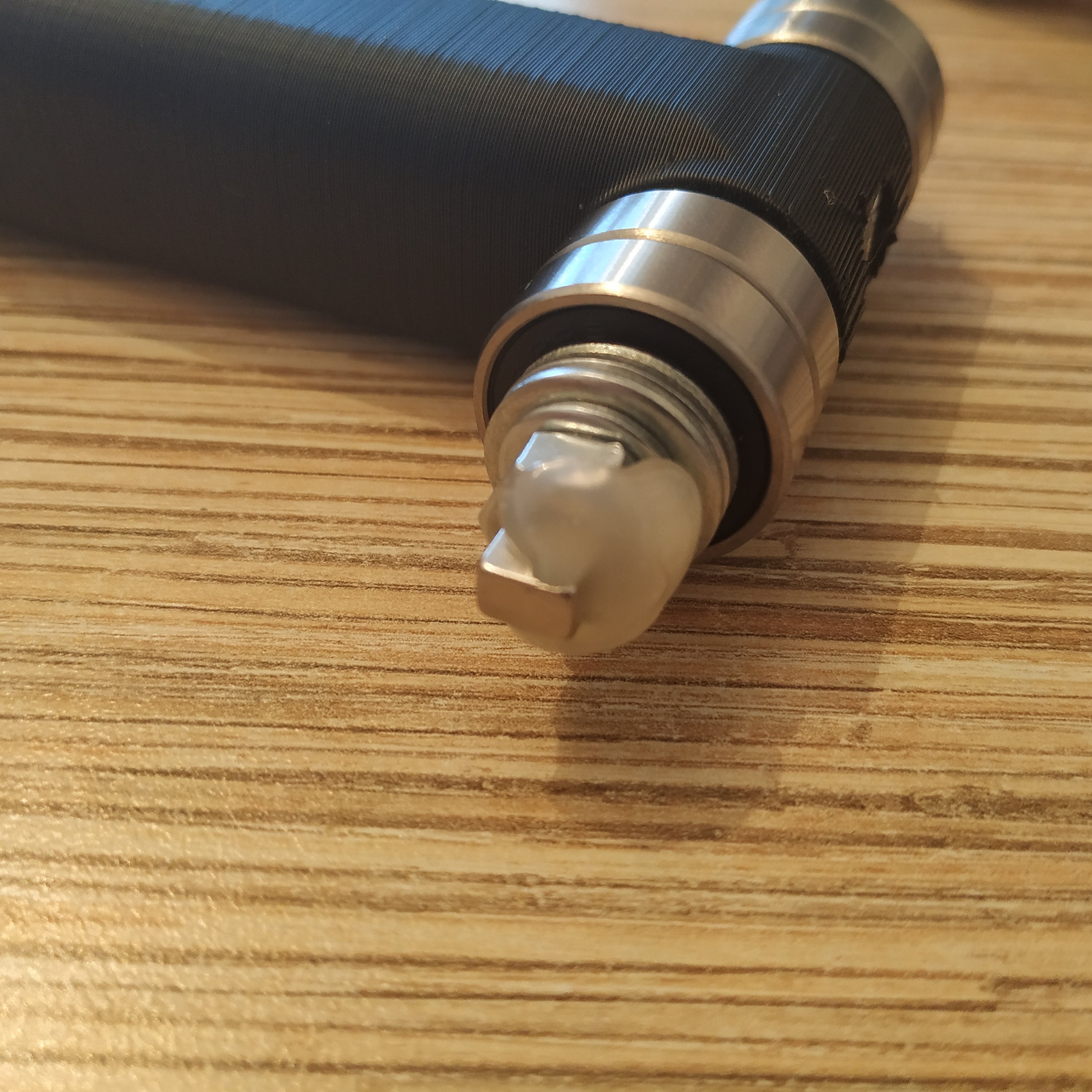
16. Put the magnet onto the nut and fix it with hot glue.
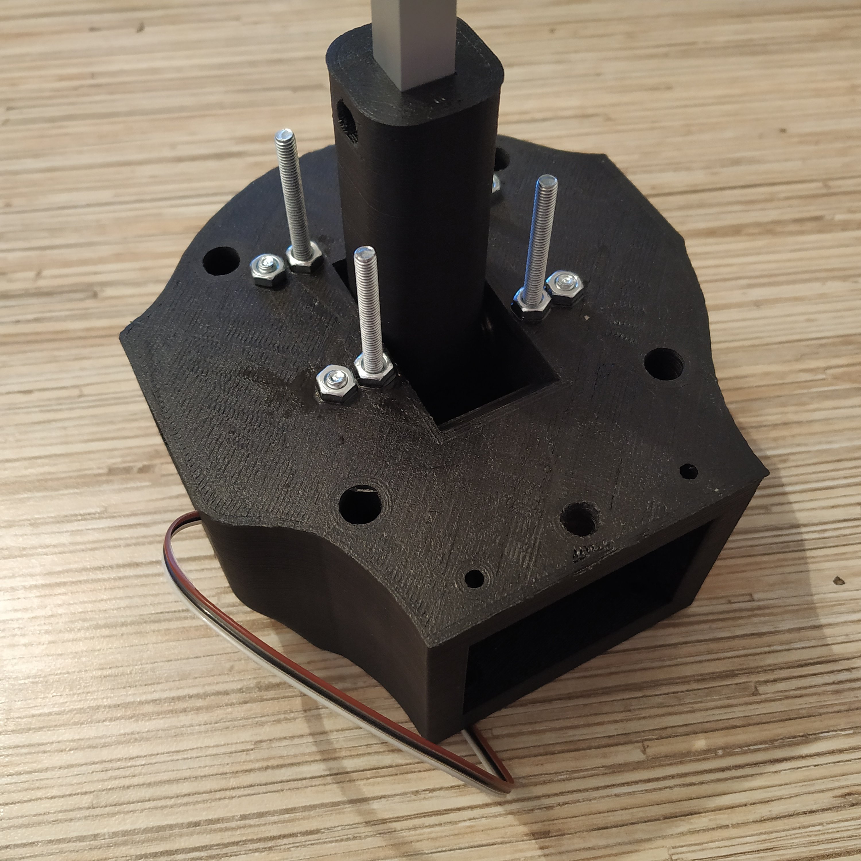
17. Insert the axis assembly into its frame.
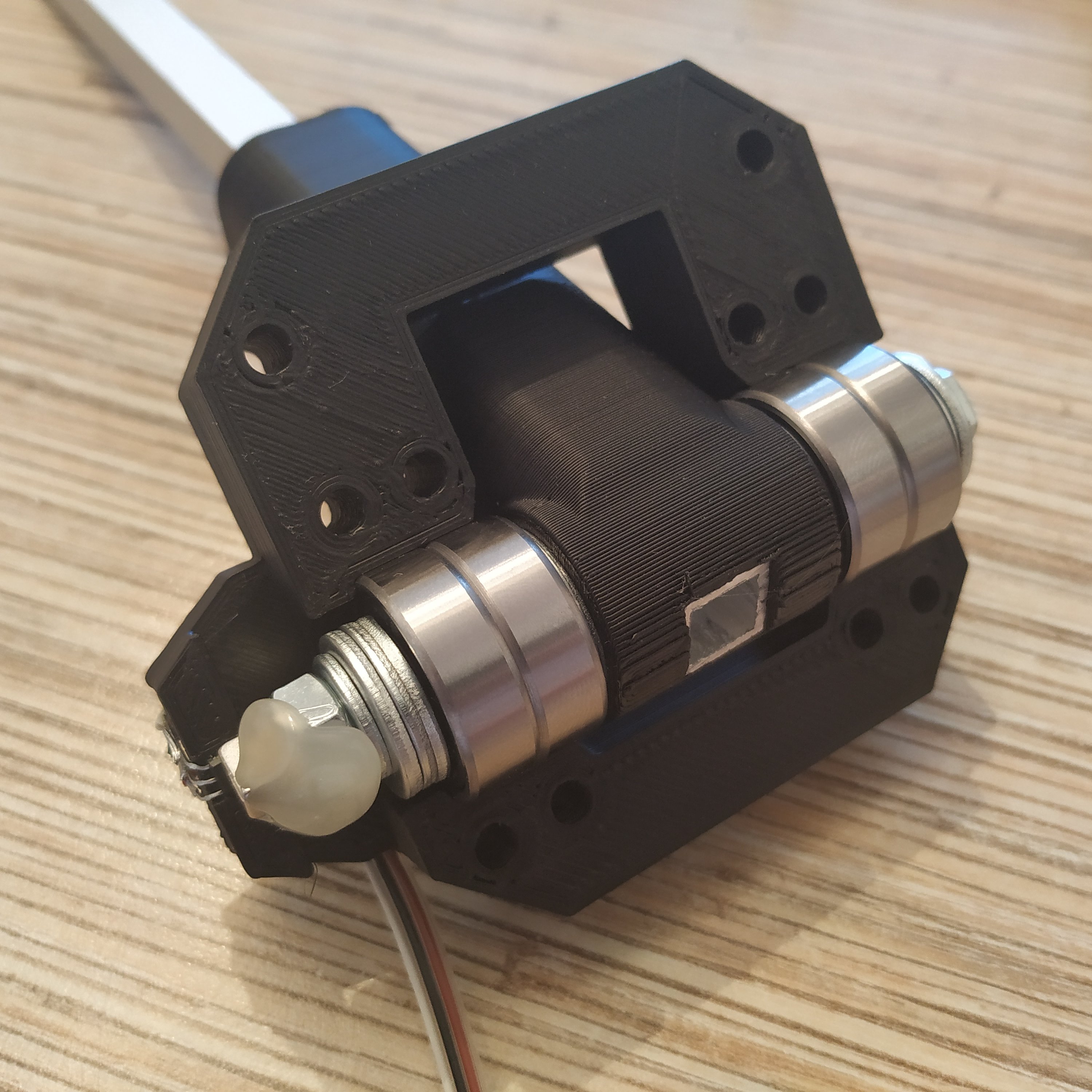
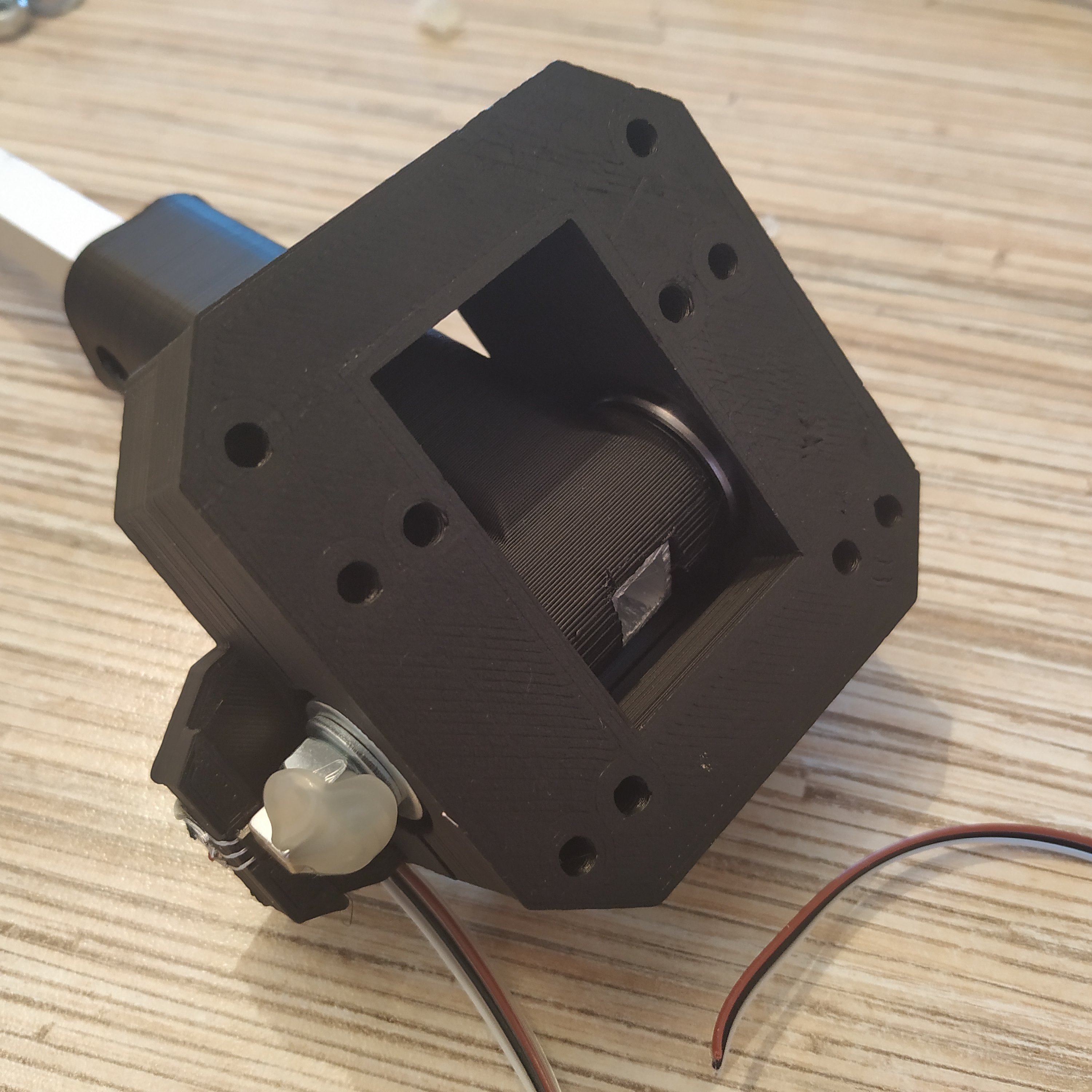
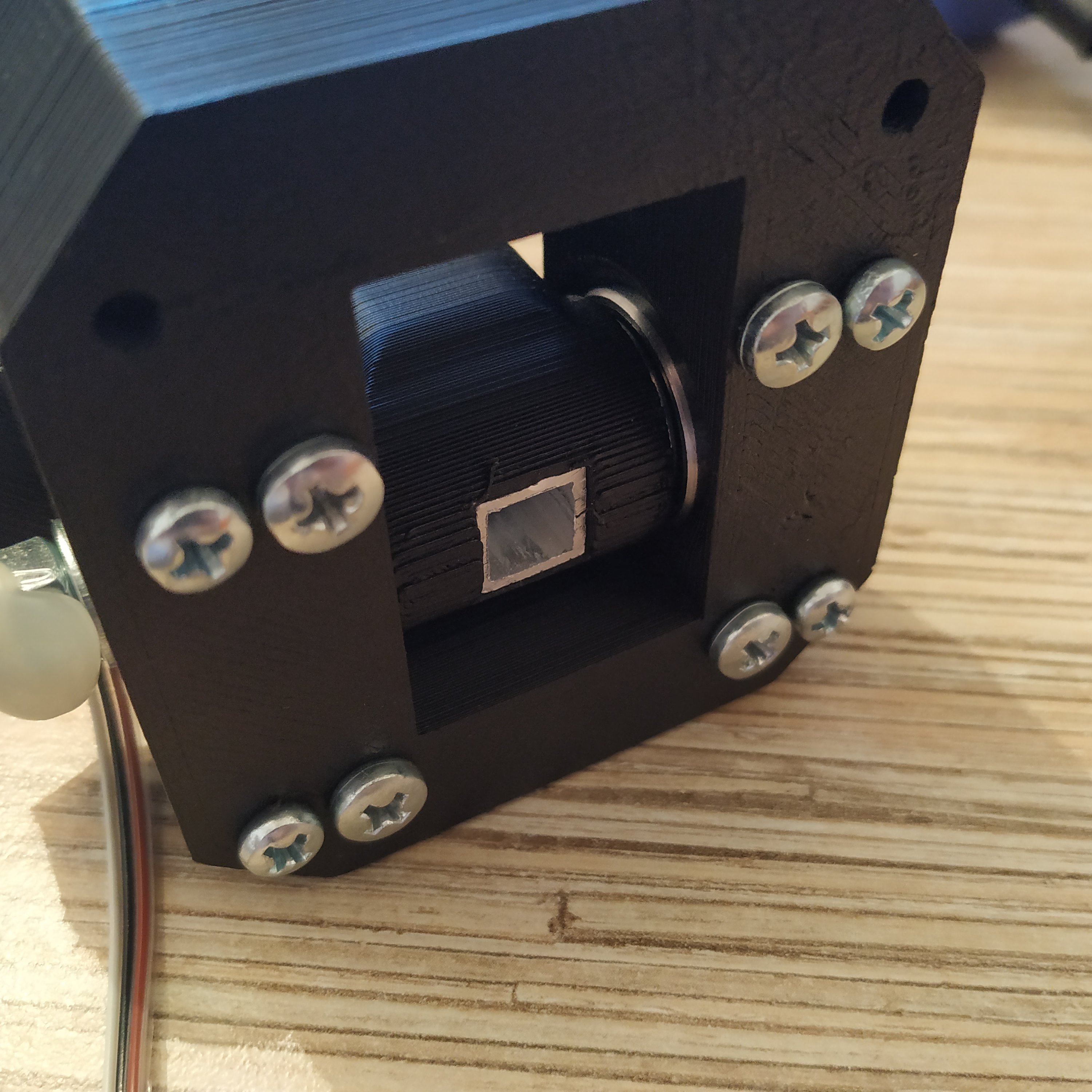
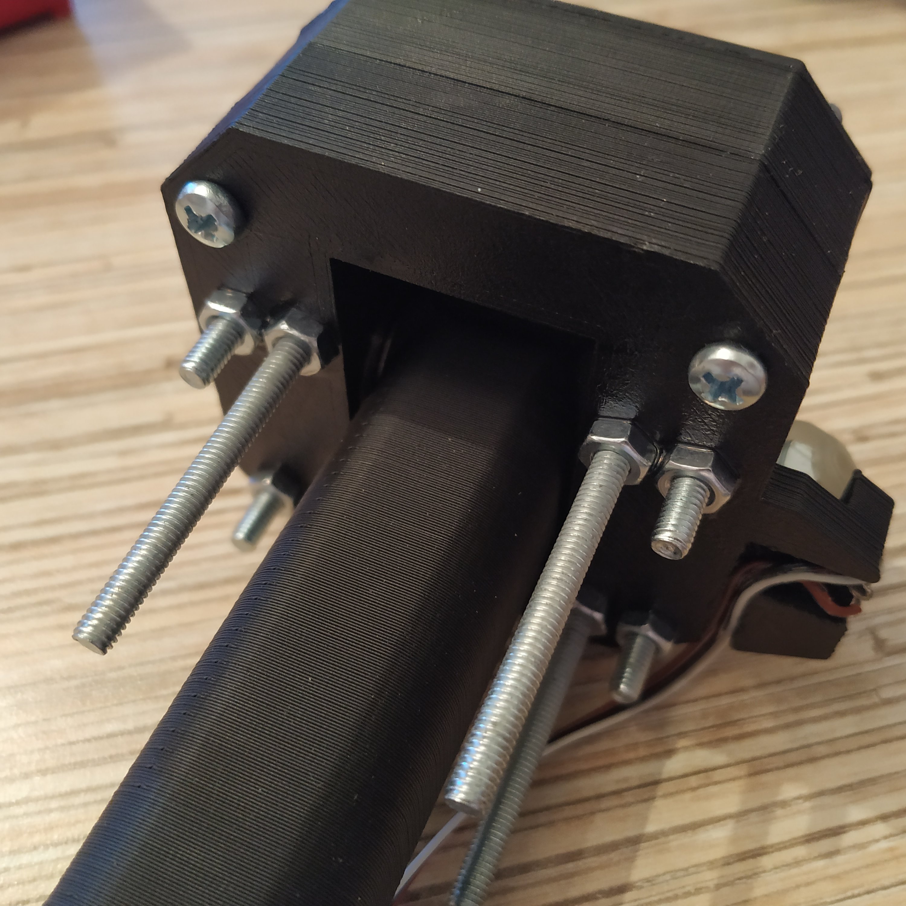
18. Insert 4 M4x40mm bolts into the frame as shown in the picture below, put nuts from the other side, use thread locker.
19. Insert 4 M4x70mm screws into the frame as shown in the picture below, add nuts, use thread locker.

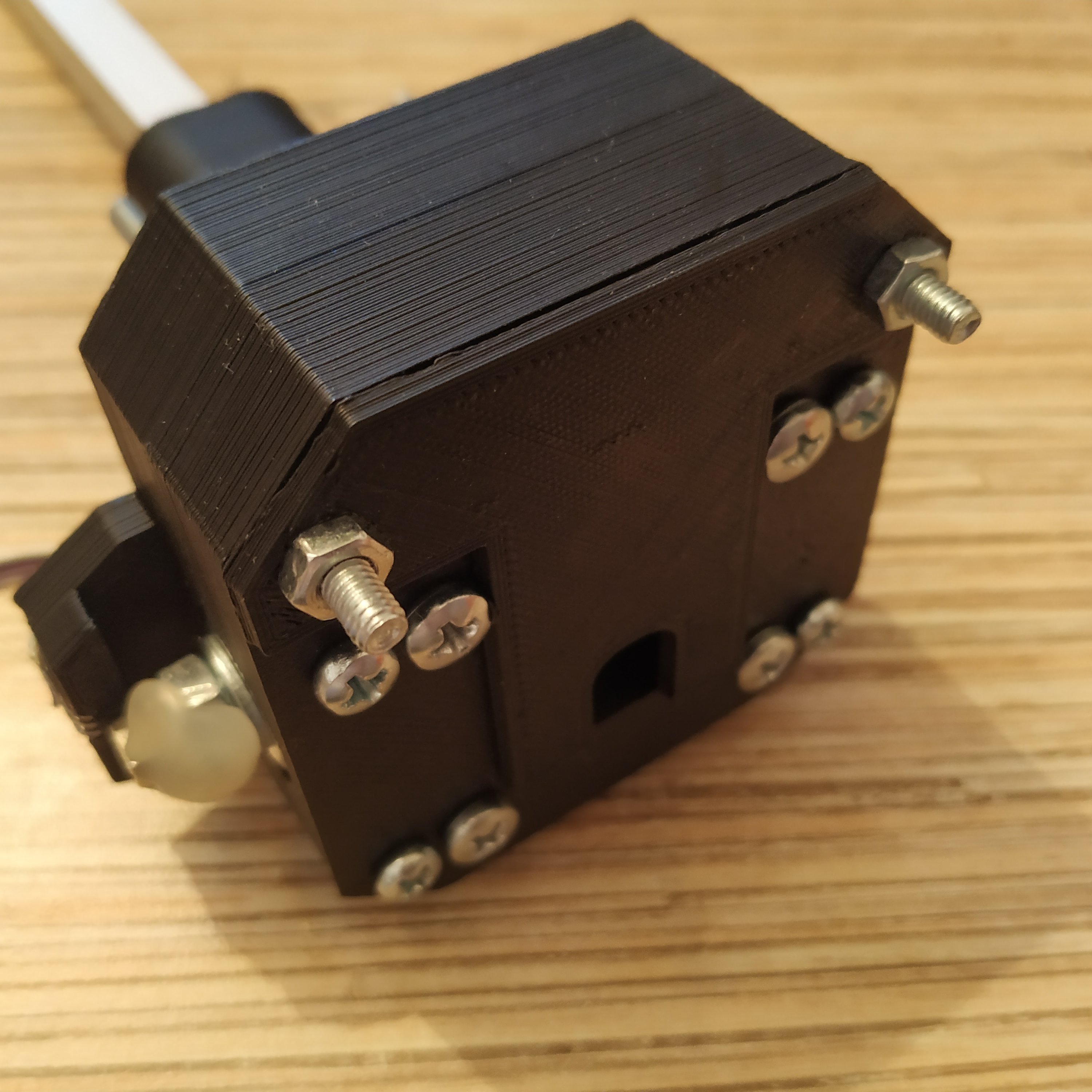
20. Put the curtain part on and fix it with 2 M4x40mm screws, add nuts, use thread locker. The axis assembly is finished!
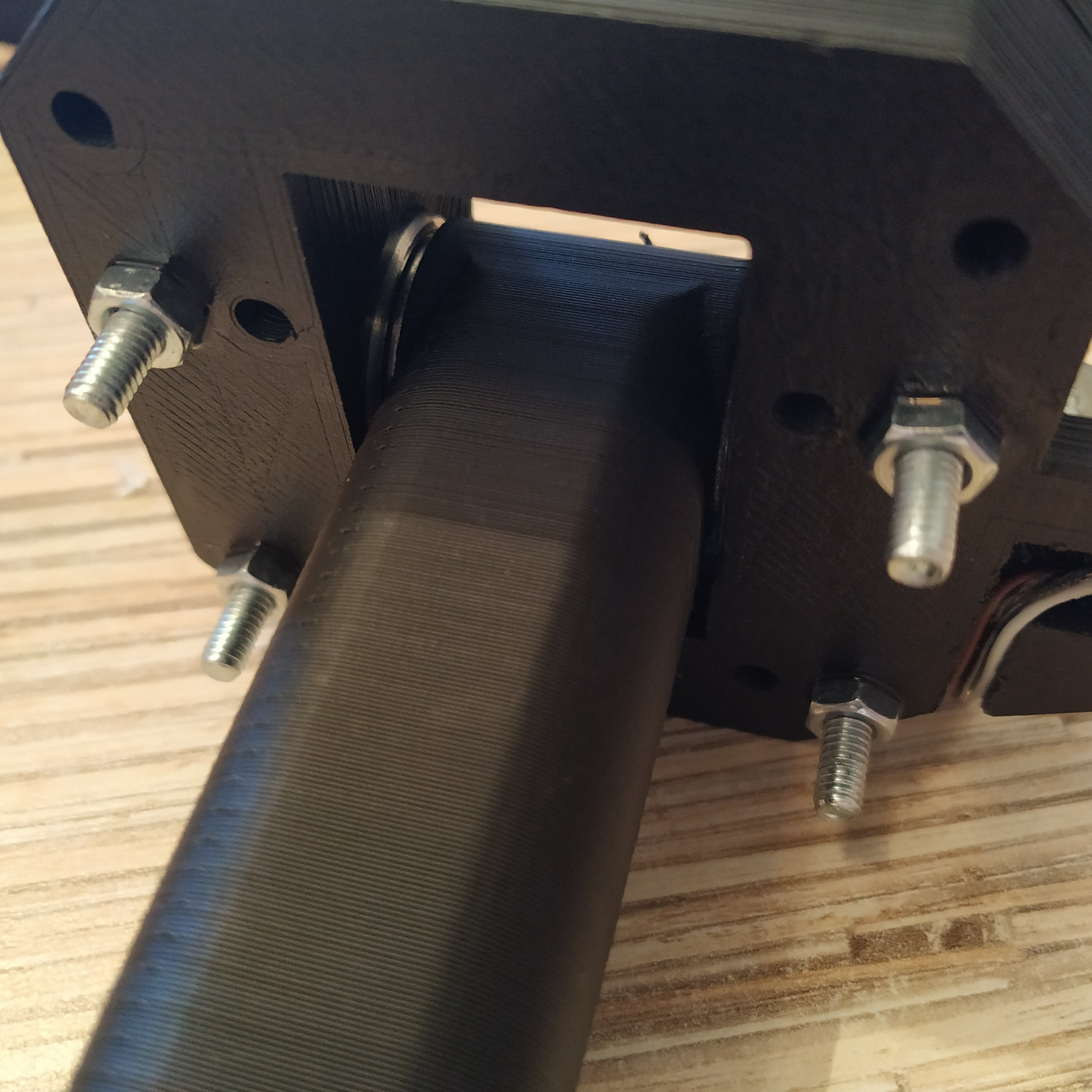
21. Insert axis assembly into the housing. Fix with nuts, use thread locker.
22. Put the friction tensioner together. To do it, widen holes in its left part with a PH0 3mm screwdriver or a drill, and insert 4 M3x50mm screws into it. After that, connect the right part of the tensioner and put nyloc nuts on. Do not tighten too much.
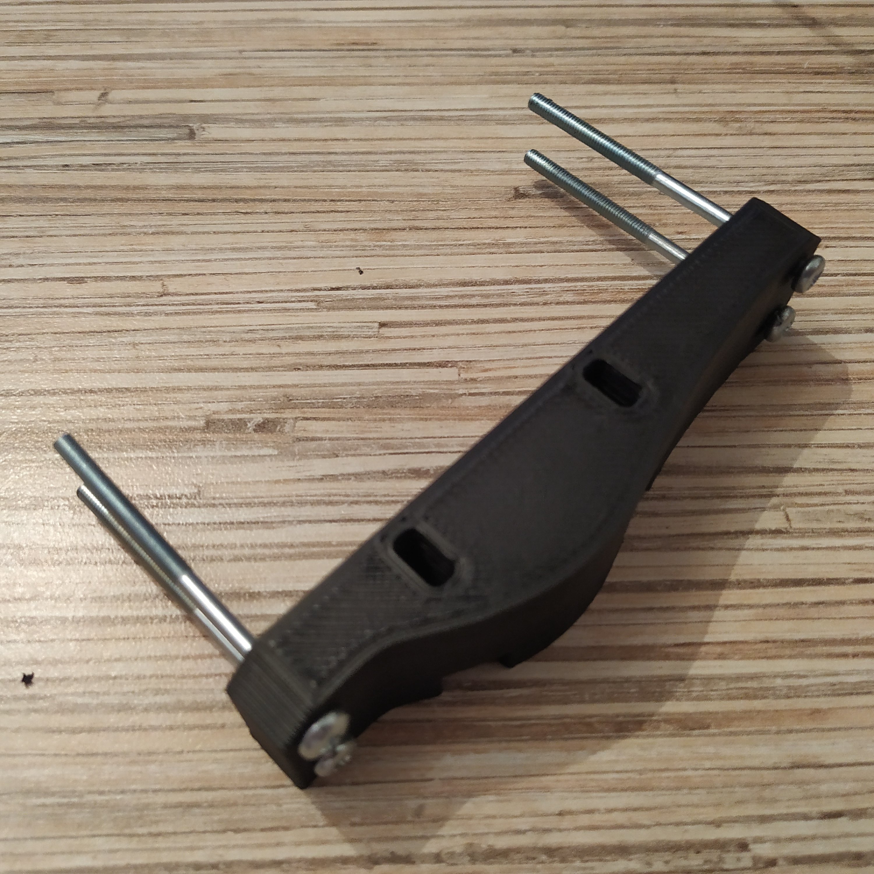
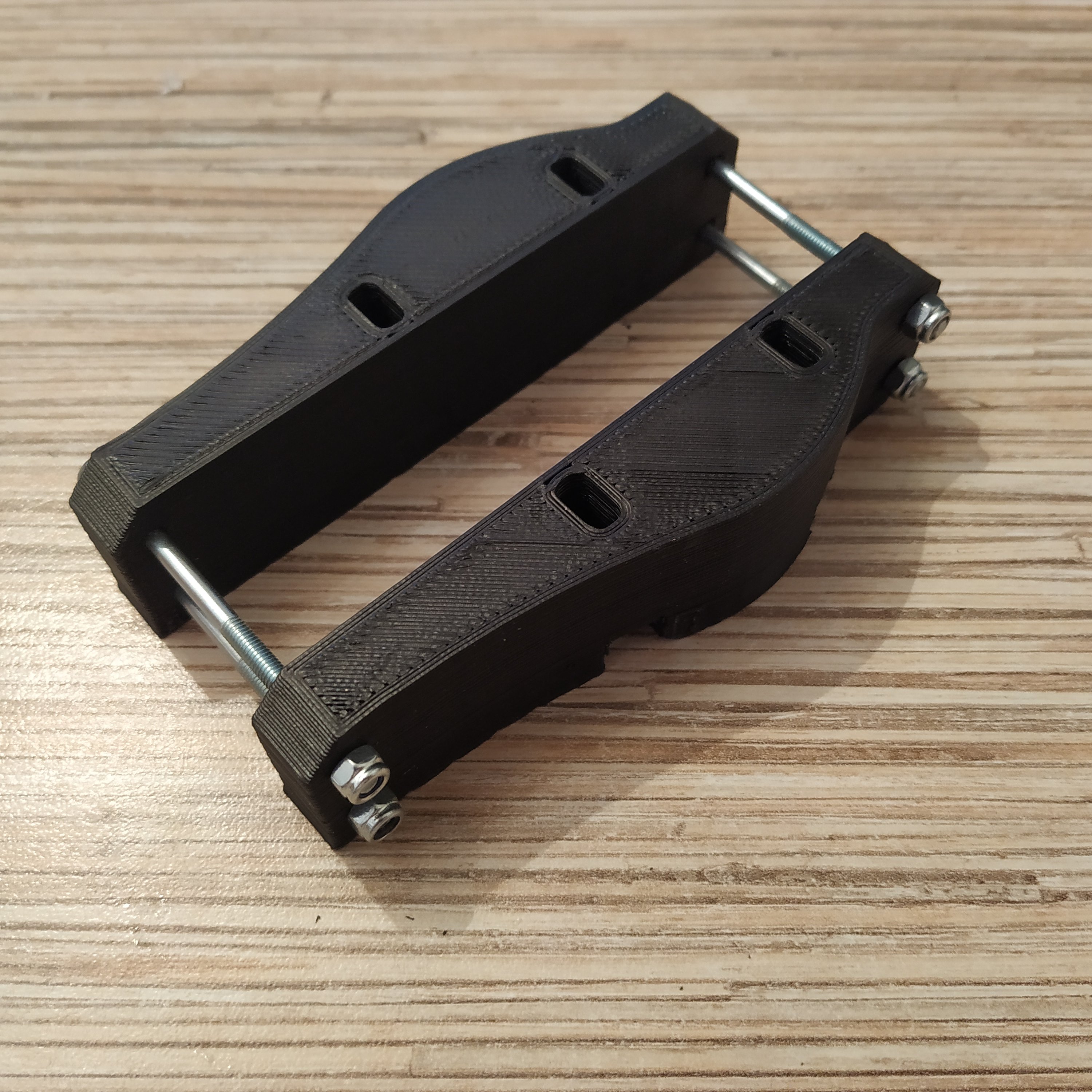
23. Attach the tensioner to the lever housing. Add and tighten 4 M4 nuts so there will be some clearance between them and the tensioner.
24. Remove 2 pins (A2, A3) from the header. Only remove A3 if you will be making a twin lever.
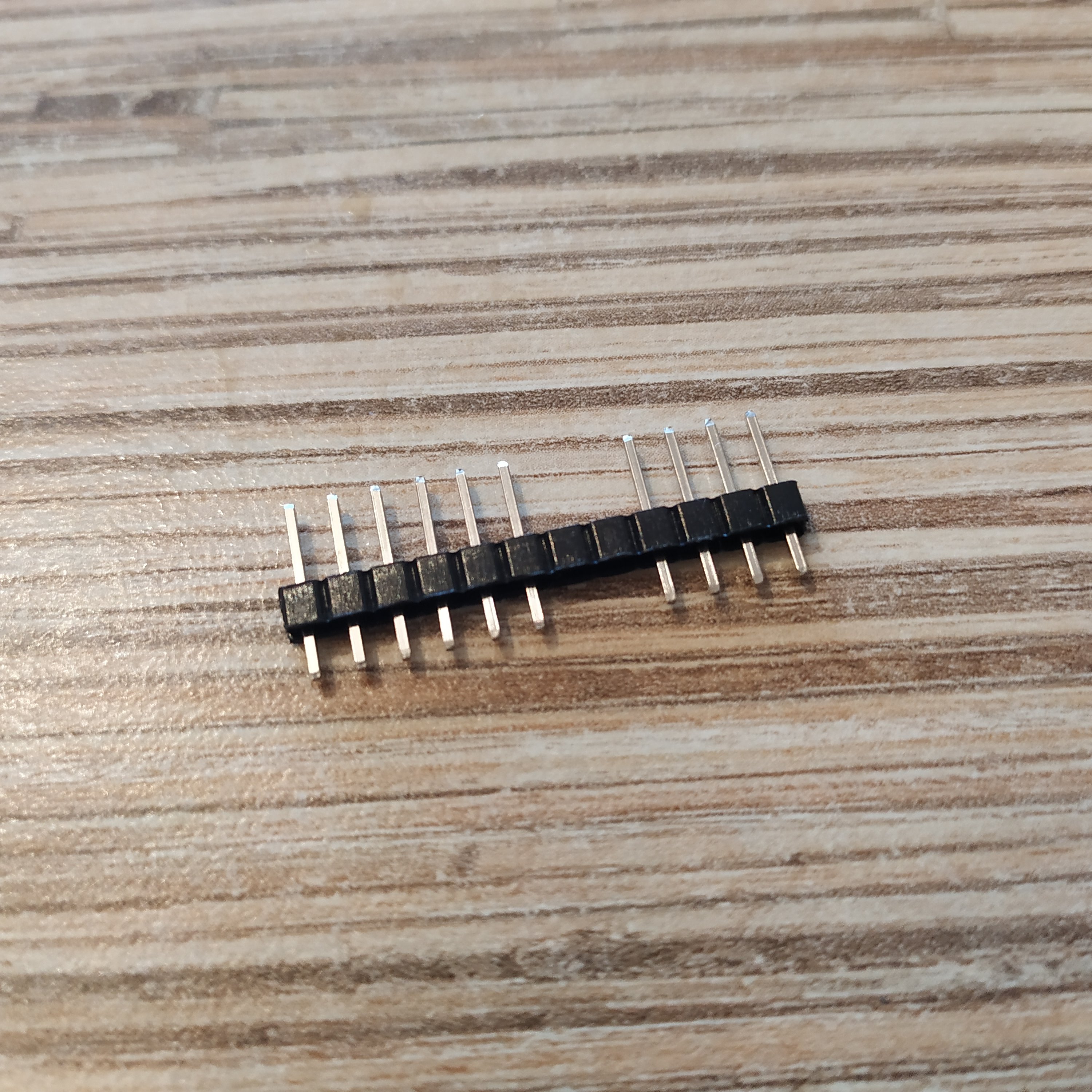
25. Solder headers to the Pro Mini board. Wash the board after that with something like Fairy. Use neutral flux! If you’re short of pins, just use some spare ones to populate A4 and A5, like ones from pins 8 and 9 of Pro Mini.
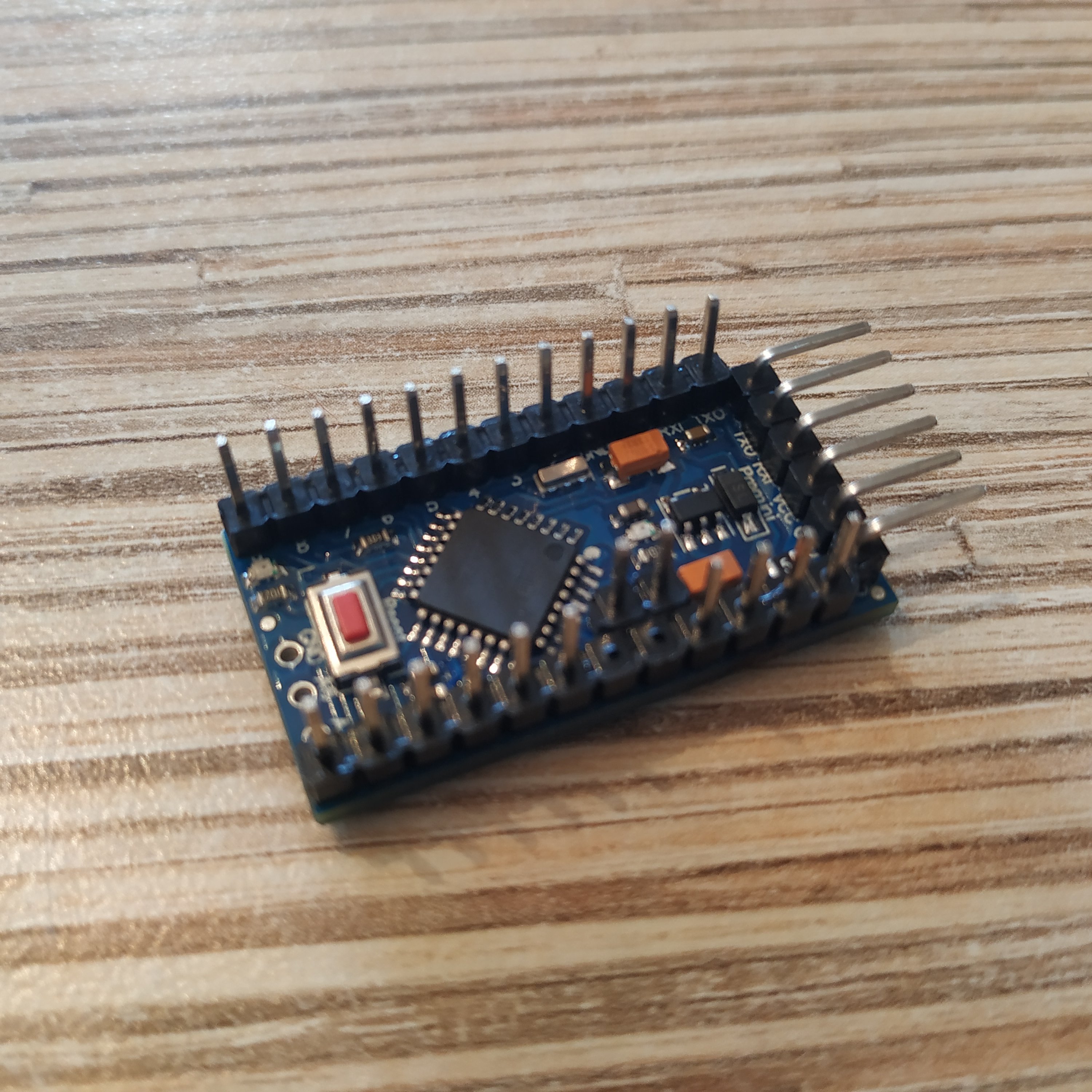
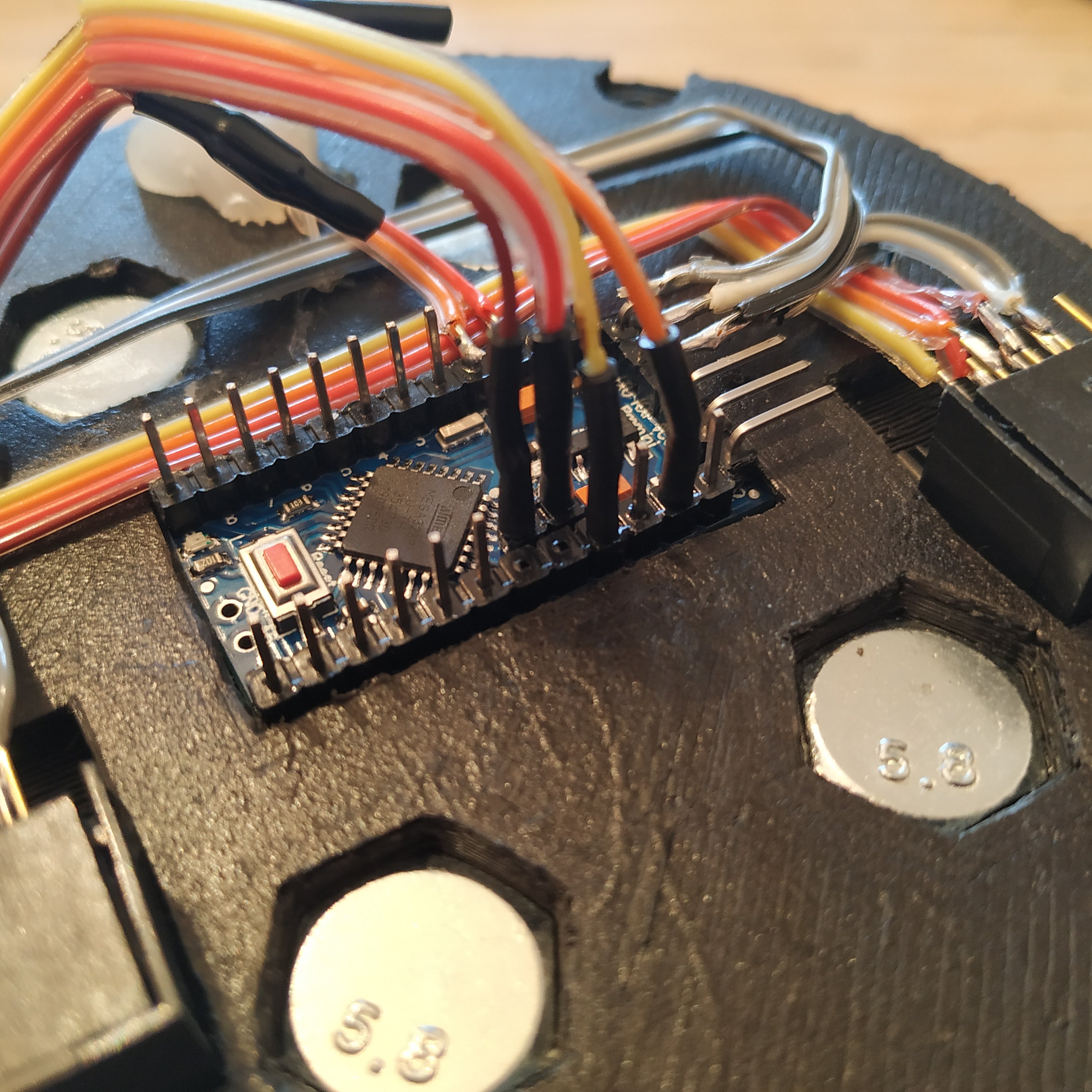
26. Bend RST and GND pins as shown in the picture:
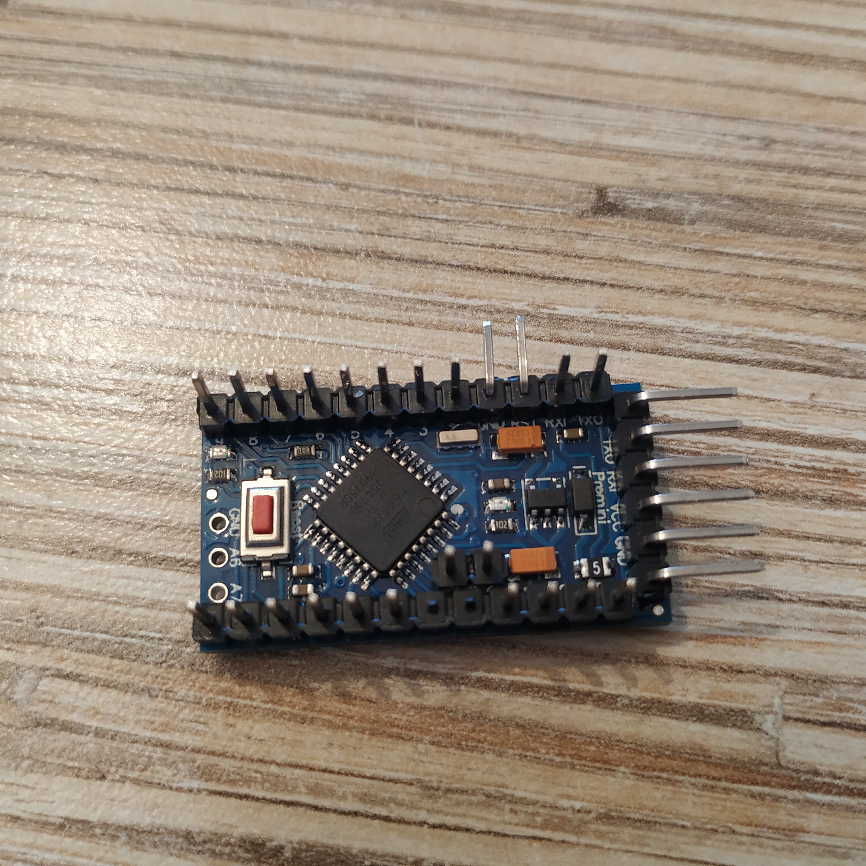
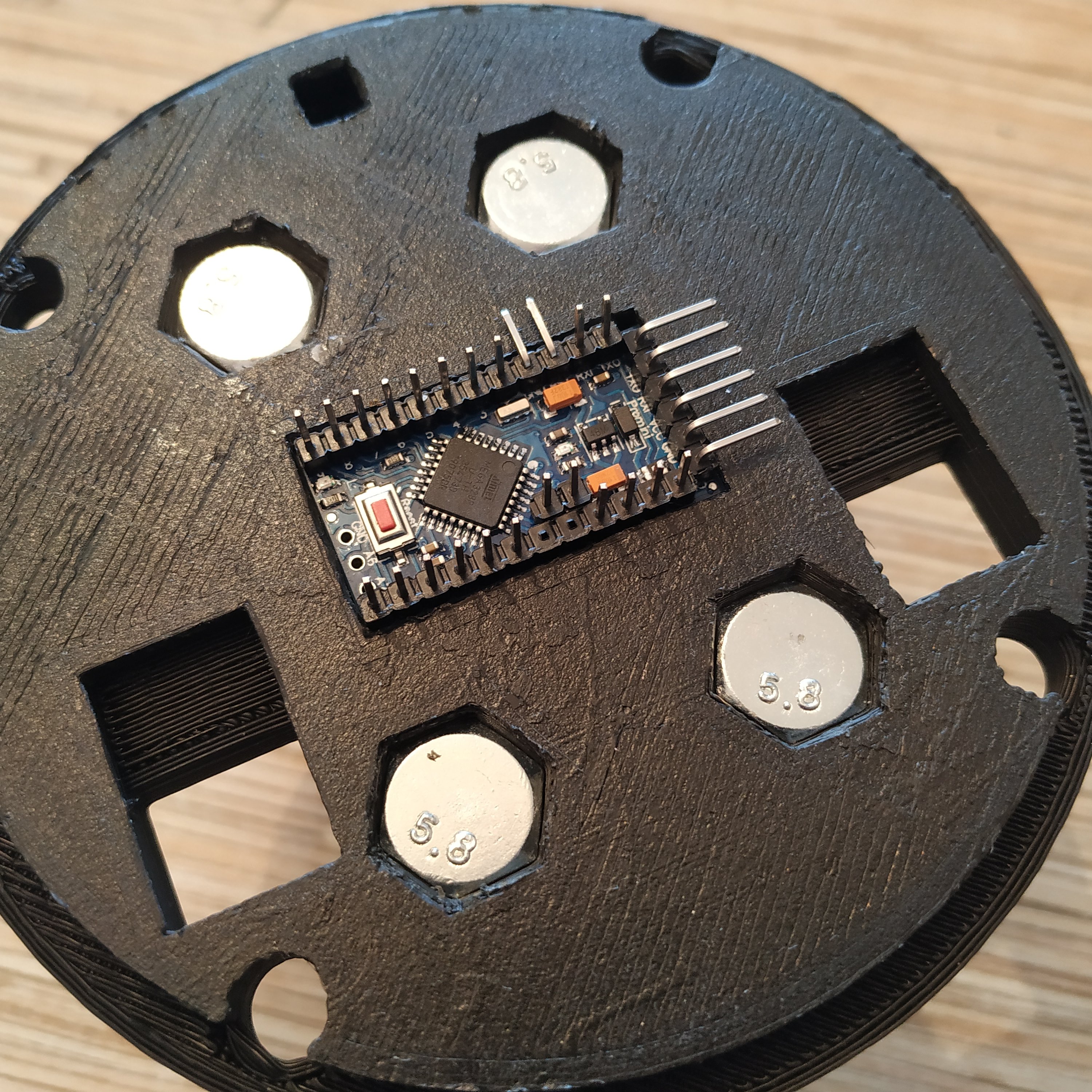
27. Put the board into its socket in the lid. Bend reset pins should point towards the button socket in the lid.
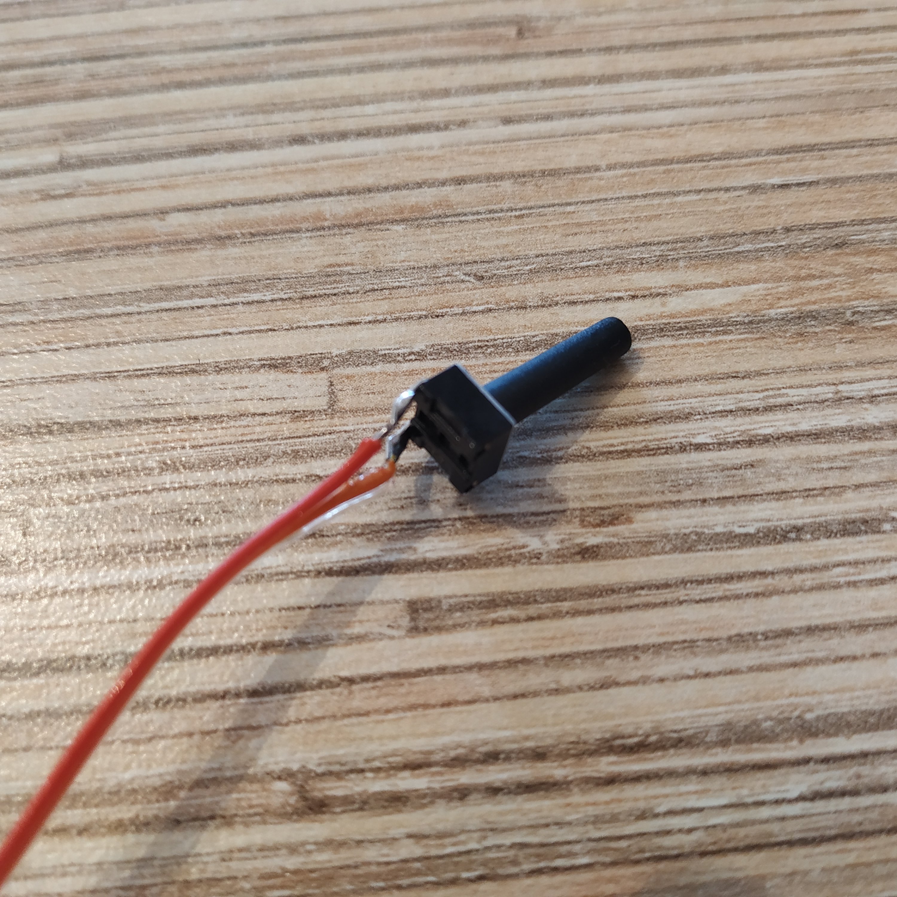
28. Solder wires to a 17mm button. Break unused pins off. Press-fit the button into its socket, secure with hot glue.
29. Solder 7-wire cables to 2 Ethernet sockets, and press-fit them into the lid.
30. Solder wires from pins 5,6,7 of sockets to Rx, Tx, DTR pins of the board. Cable management will help a lot!
31. Add one more piece of 4-wire i2c cable and make an I2C cable tie. Don’t forget to add an I2C cable for the head if needed!
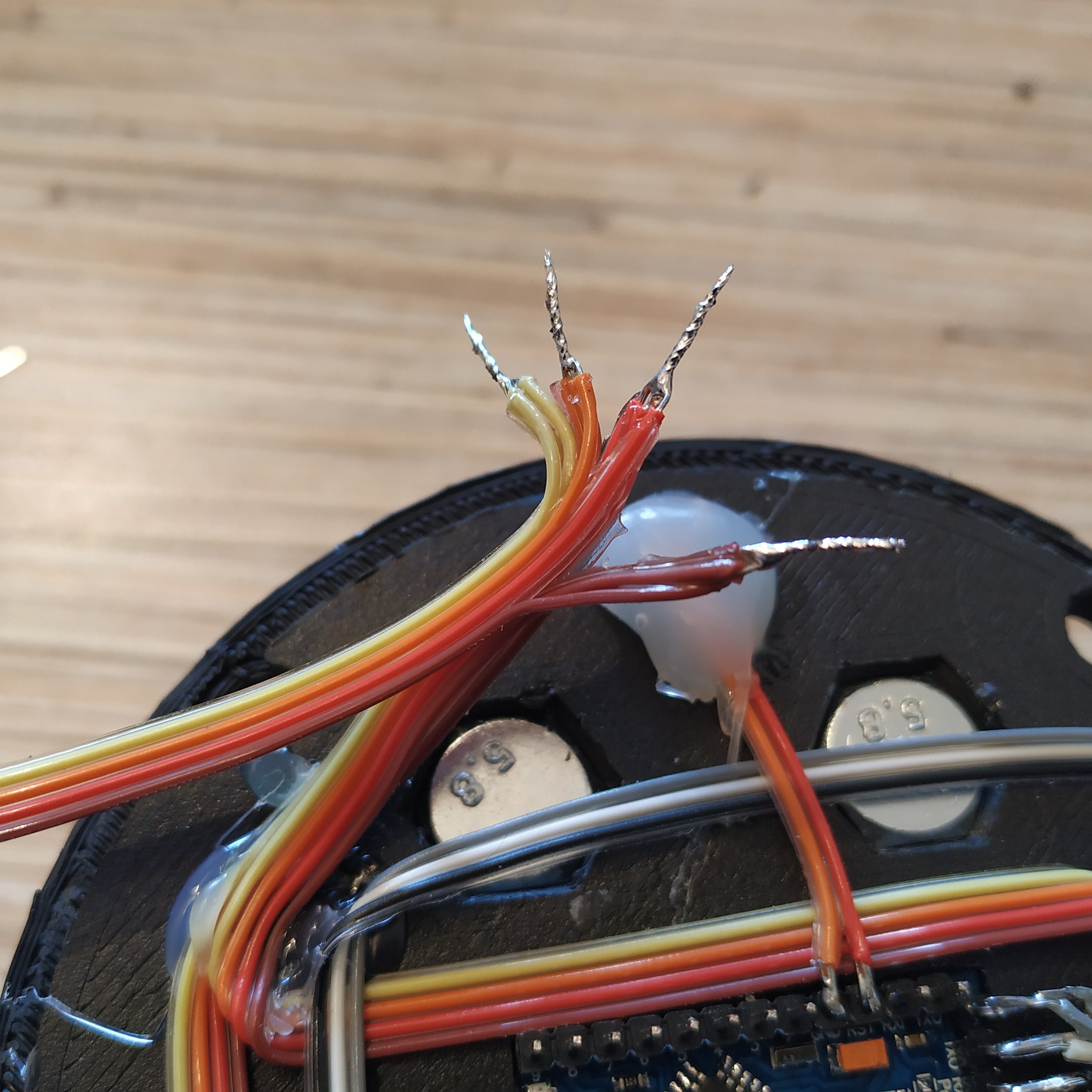
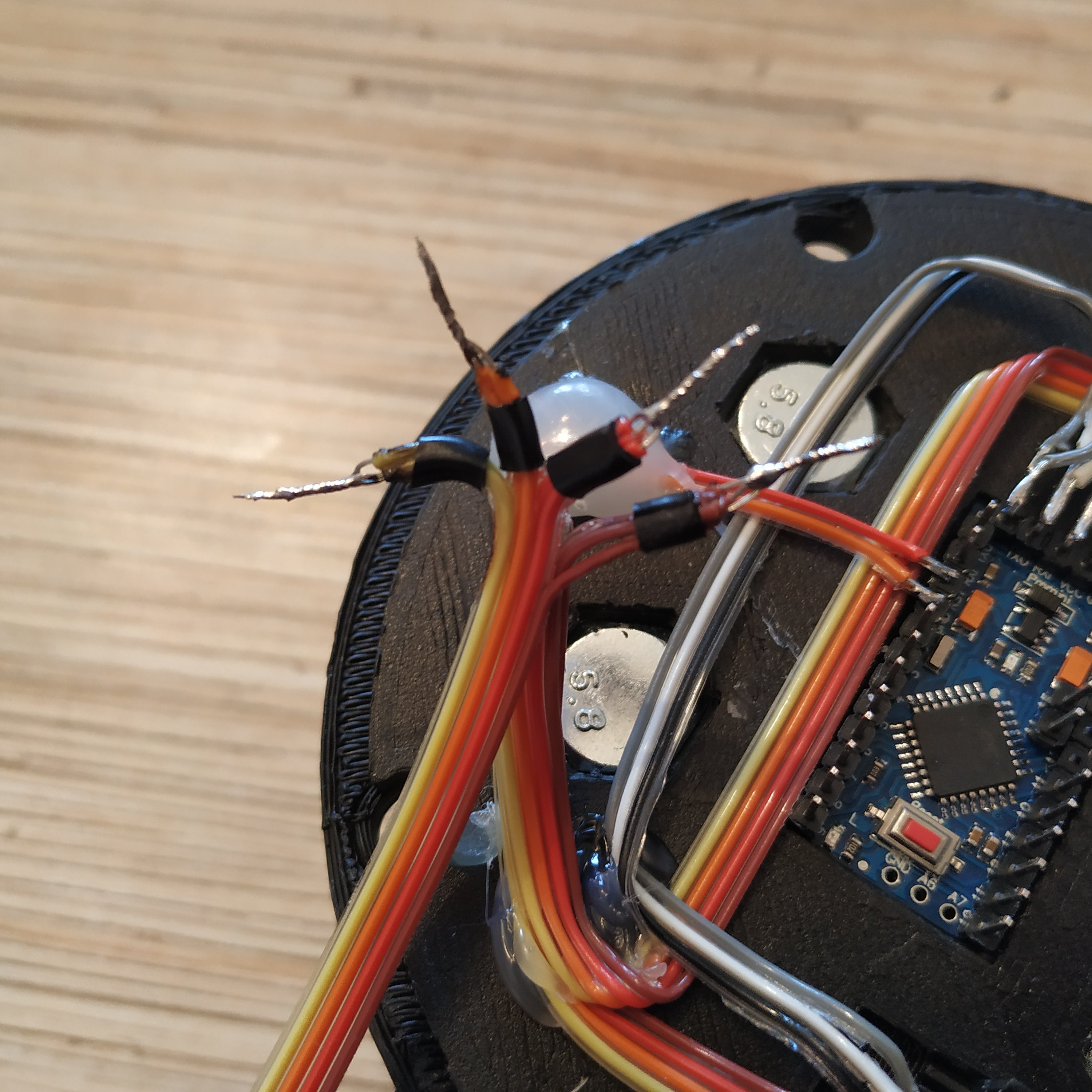
32. Connect I2C cable to VCC,GND,SCL(A5),SDA(A4)
33. Connect the left wire of the mode switch to pin 2, right one to pin 3, middle one to GND next to RST pin.
34. Solder SS495A1 cable to A0, VCC, and GND to VCC and GND on the UART header. Connect throttle pot to A1, VCC, and GND if one is present.
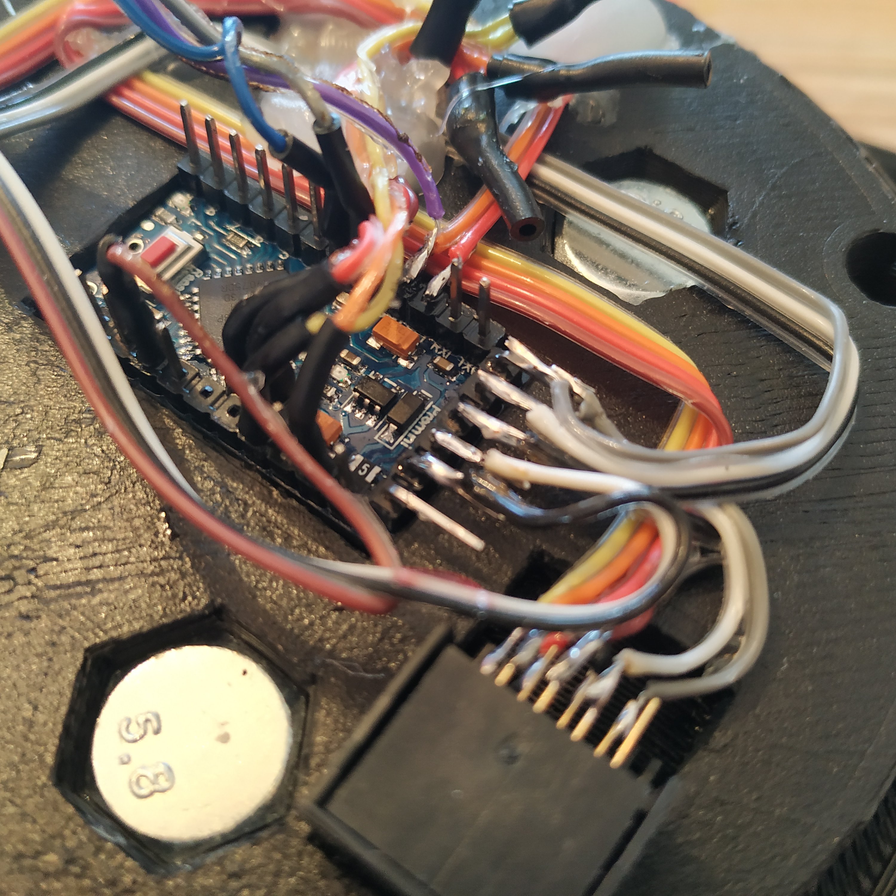
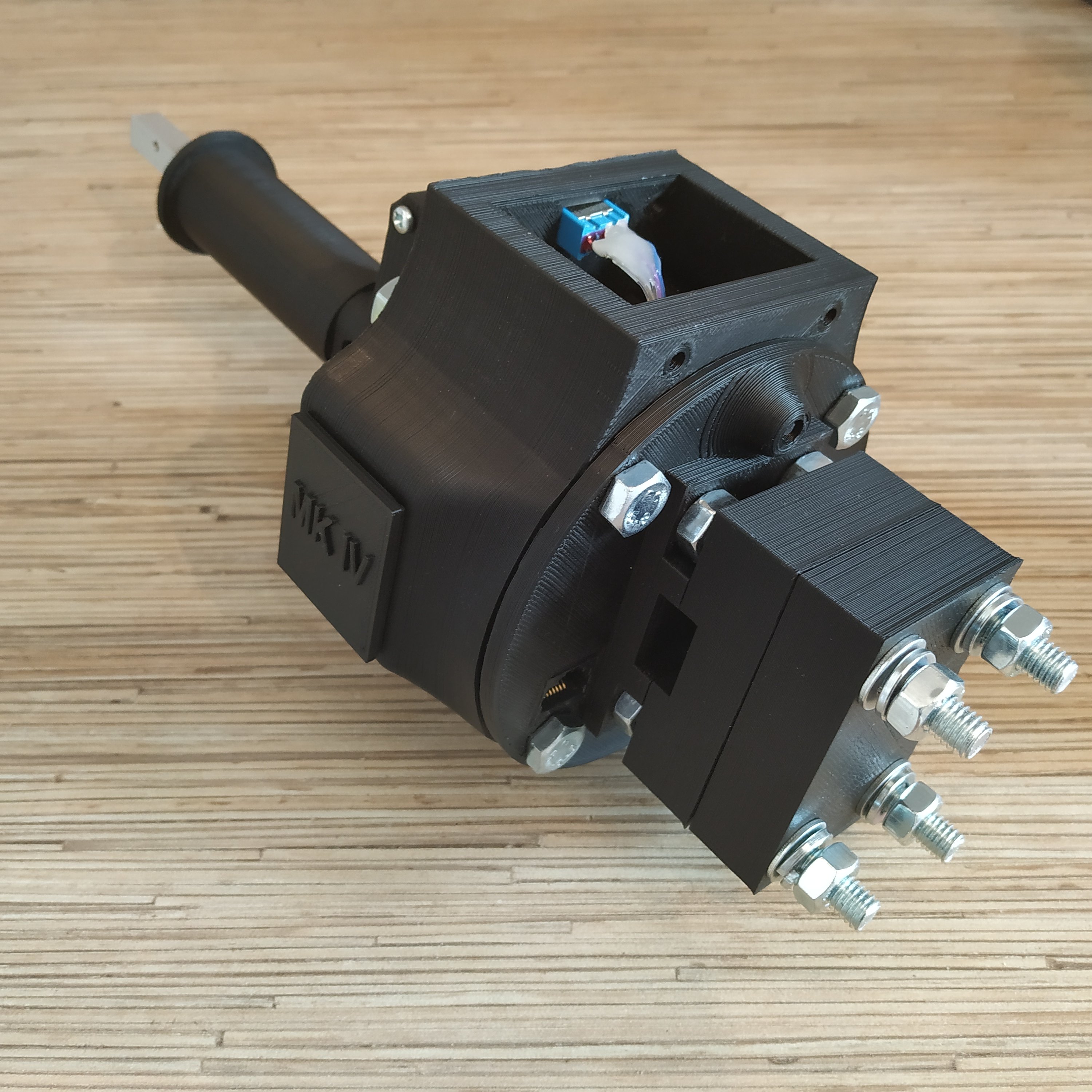
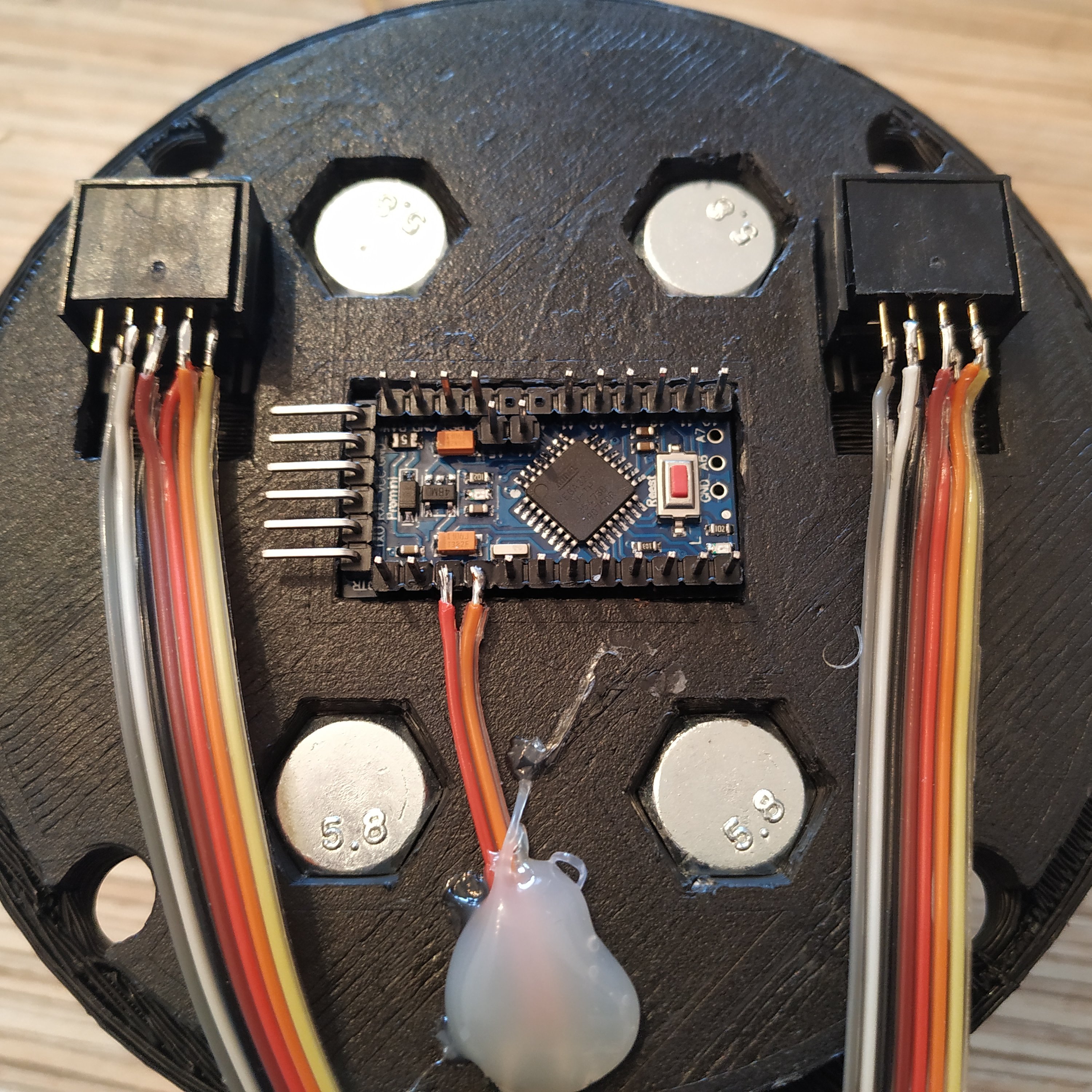
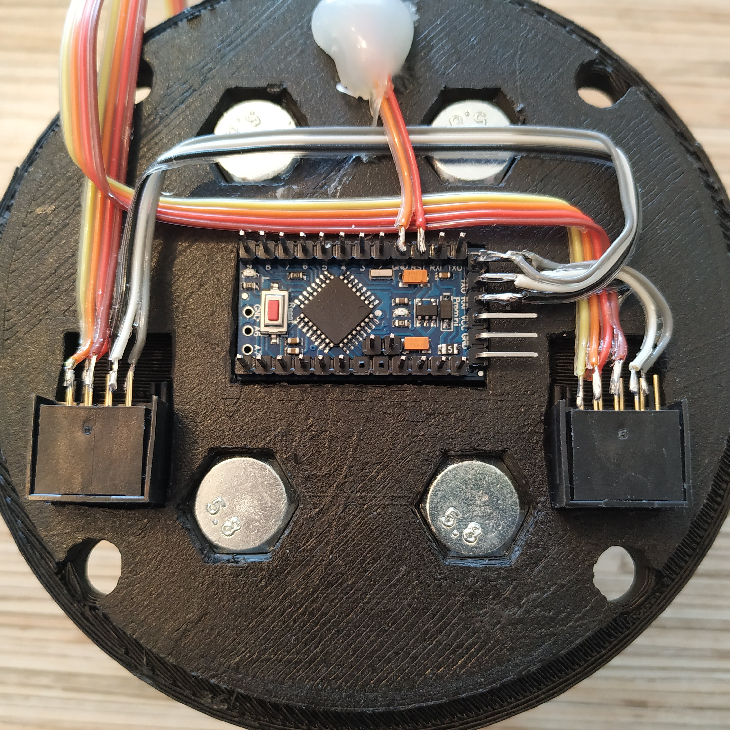
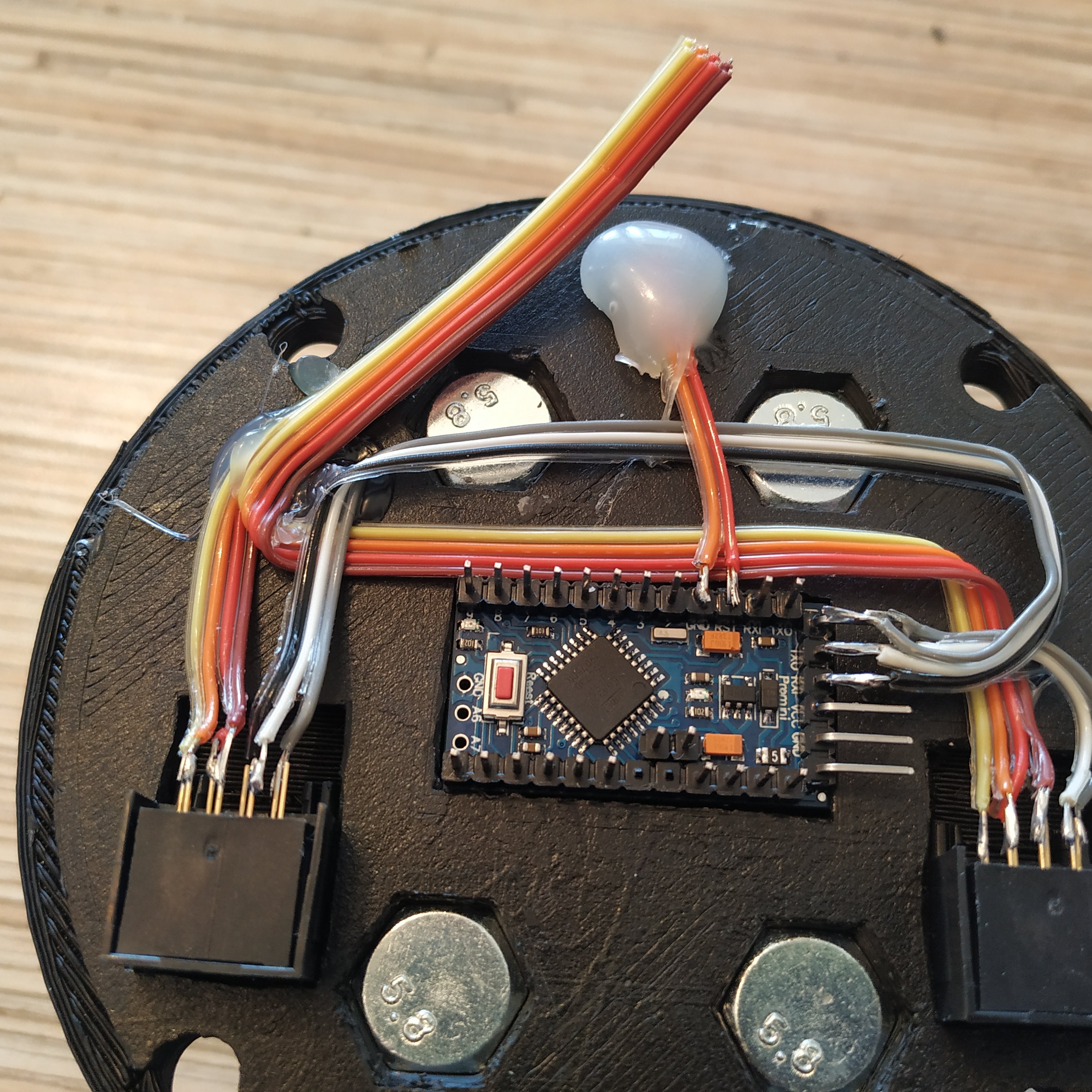
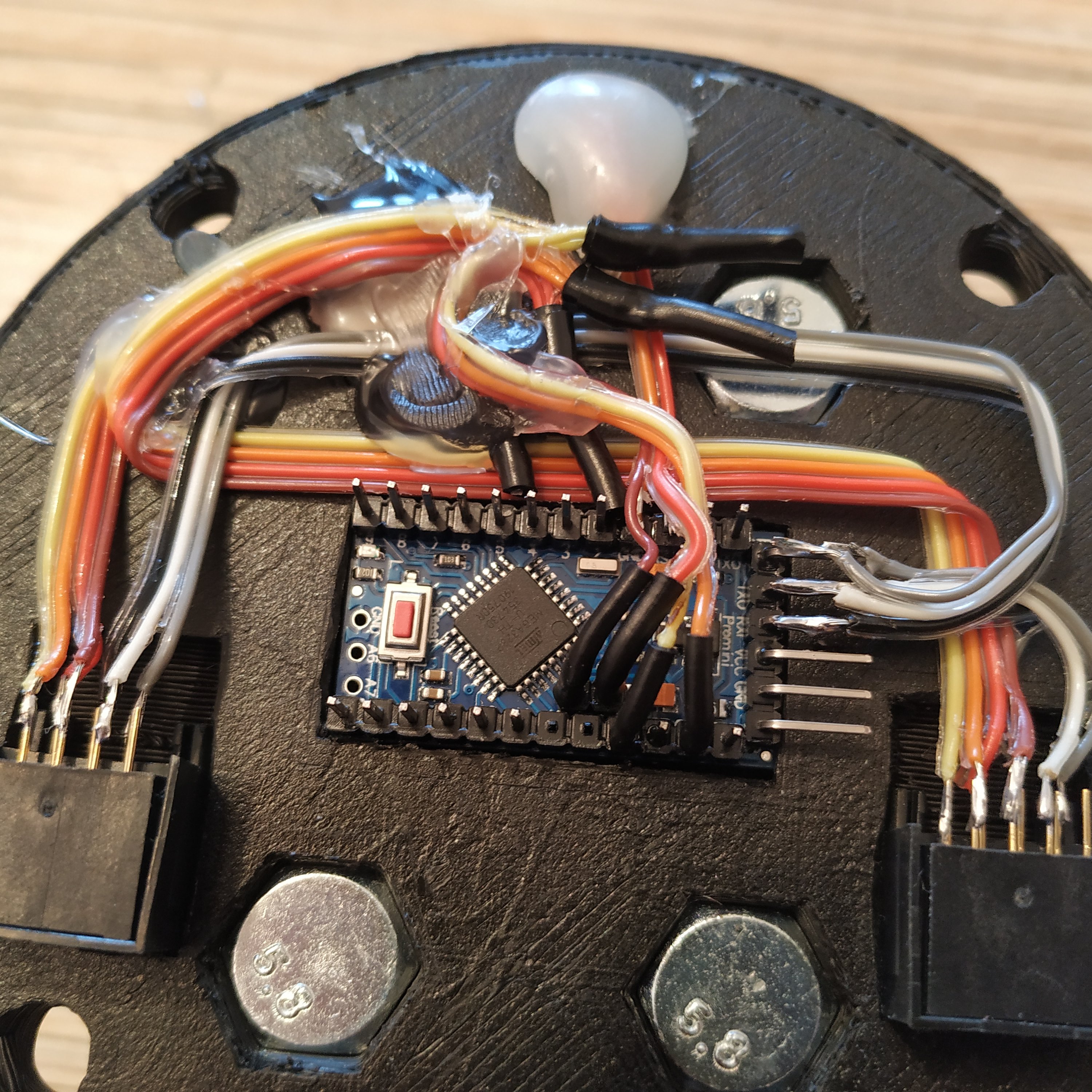
35. Here’s how the assembly should look:
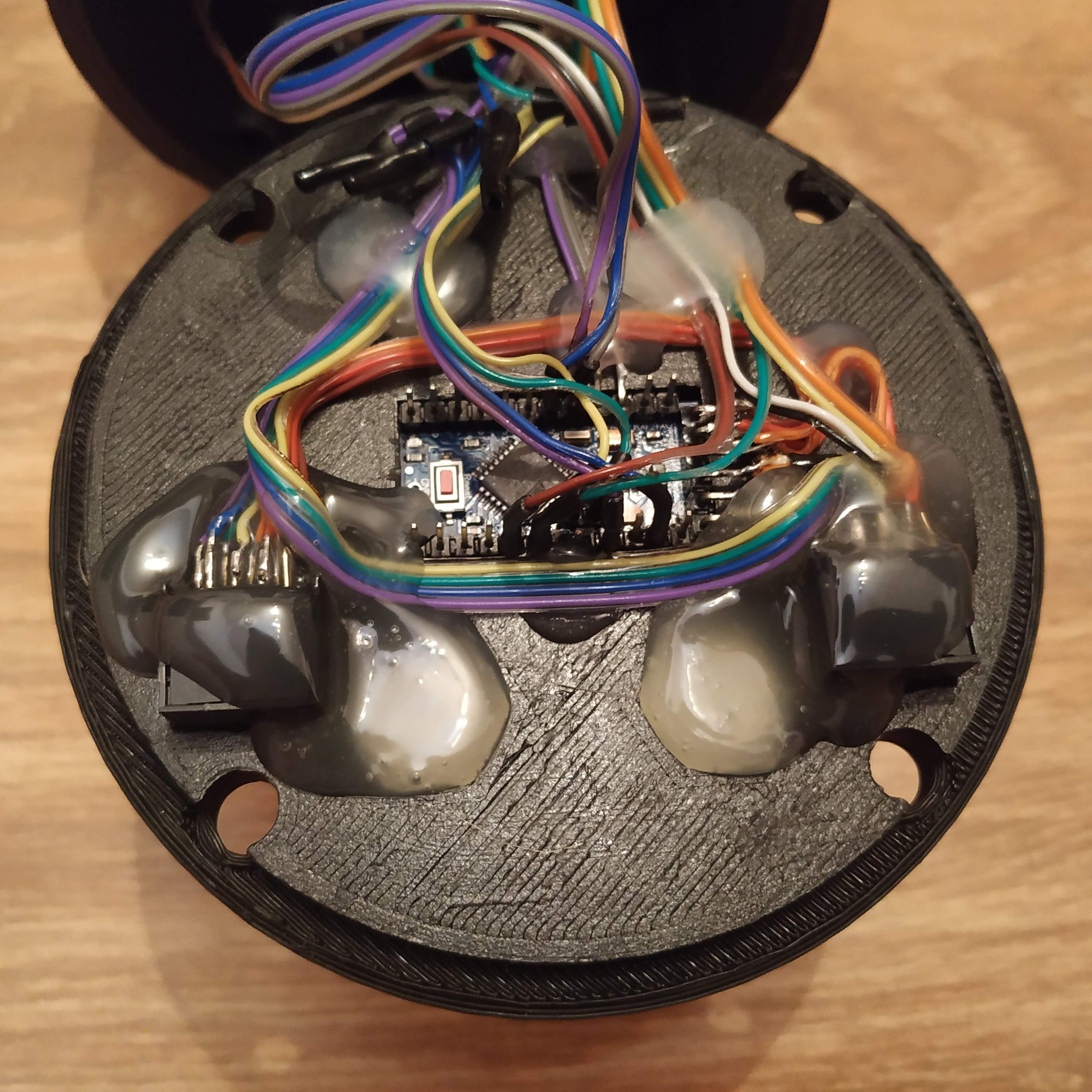
Mode switch left pin -> Pro Mini pin 2
Mode switch GND -> GND next to RST
Mode switch right pin -> Pro Mini pin 3
MCU RST button -> between RST and GND next to it
SS495A1 pin 1 -> THR POT left pin (on the left when the lever is mounted as usual) VCC cable tie <- Pro Mini VCC <- Ethernet sockets pin 1
SS495A1 pin 2 -> THR POT right pin -> GND cable tie <- Pro Mini GND <- Ethernet sockets pin 2
A0 -> SS495A1 signal
A1 -> THR POT signal
A4 -> SDA cable tie <- Ethernet sockets pin 3
A5 -> SCL cable tie <- Ethernet sockets pin 4
Collective head I2C cable -> VCC, GND, SCL,SDA cable ties
Pro Mini Rx -> Ethernet sockets pin 5
Pro Mini Tx -> Ethernet sockets pin 6
Pro Mini DTR -> Ethernet sockets pin 7
If everything looks correct, flash the board with its firmware using FT232TL based adapter (or any other) and a UART- Ethernet cable connected as follows:
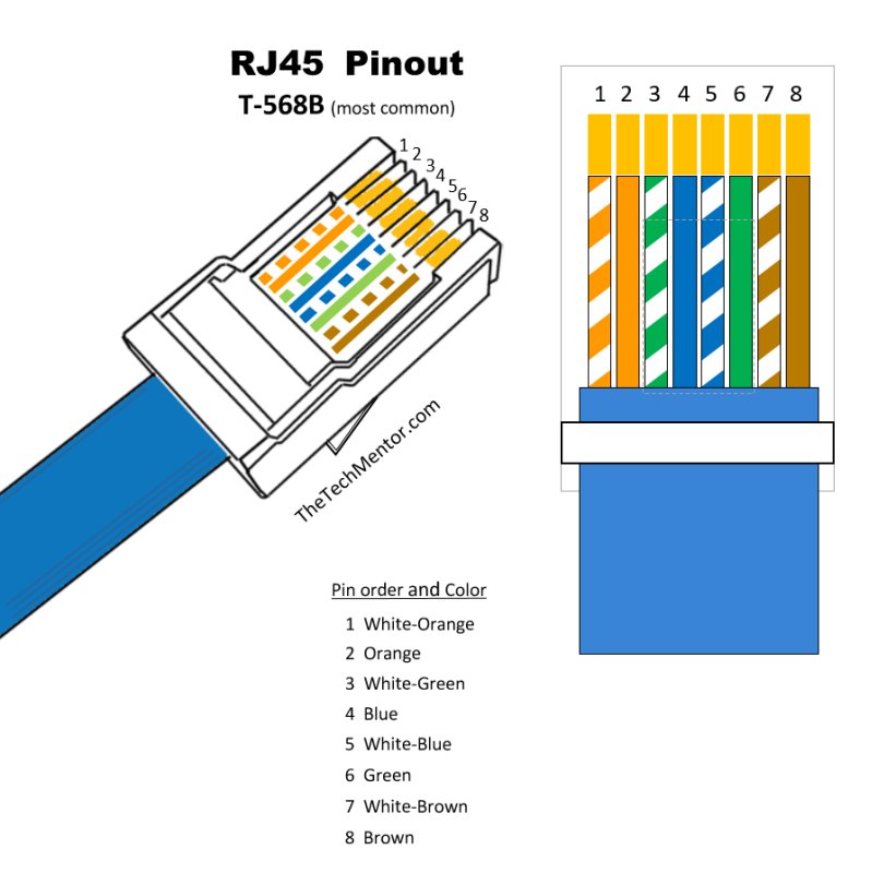
WHITE-ORANGE -> VCC
ORANGE -> GND
WHITE-GREEN -> NC
BLUE -> NC
WHITE-BLUE -> USB-UART TX
GREEN -> USB-UART RX
WHITE-BROWN -> USB-UART DTR (if available)
BROWN -> NC
We will need to calibrate the lever now. To do it, uncomment
#define CALIBRATE
and comment out map functions:
z = map(z,0,936,0,1023); rz = map(rz,32,1023,1023,0);
Then, flash the firmware and look into serial output. Adjust the bolt of the axis until the “zero” position of the lever will correspond to 0 in serial output. Check that the range you’re getting is close to 0-1000.
Replace 1st 2 values in map functions with values you see. Uncomment these functions and comment out the CALIBRATE line. Reflash the firmware, check there’s no serial output, and that’s it.
36. After finishing with the assembling of the lever body, put the lid onto the housing. Fix with 4 M8x70 or M8x75mm bolts and nuts.
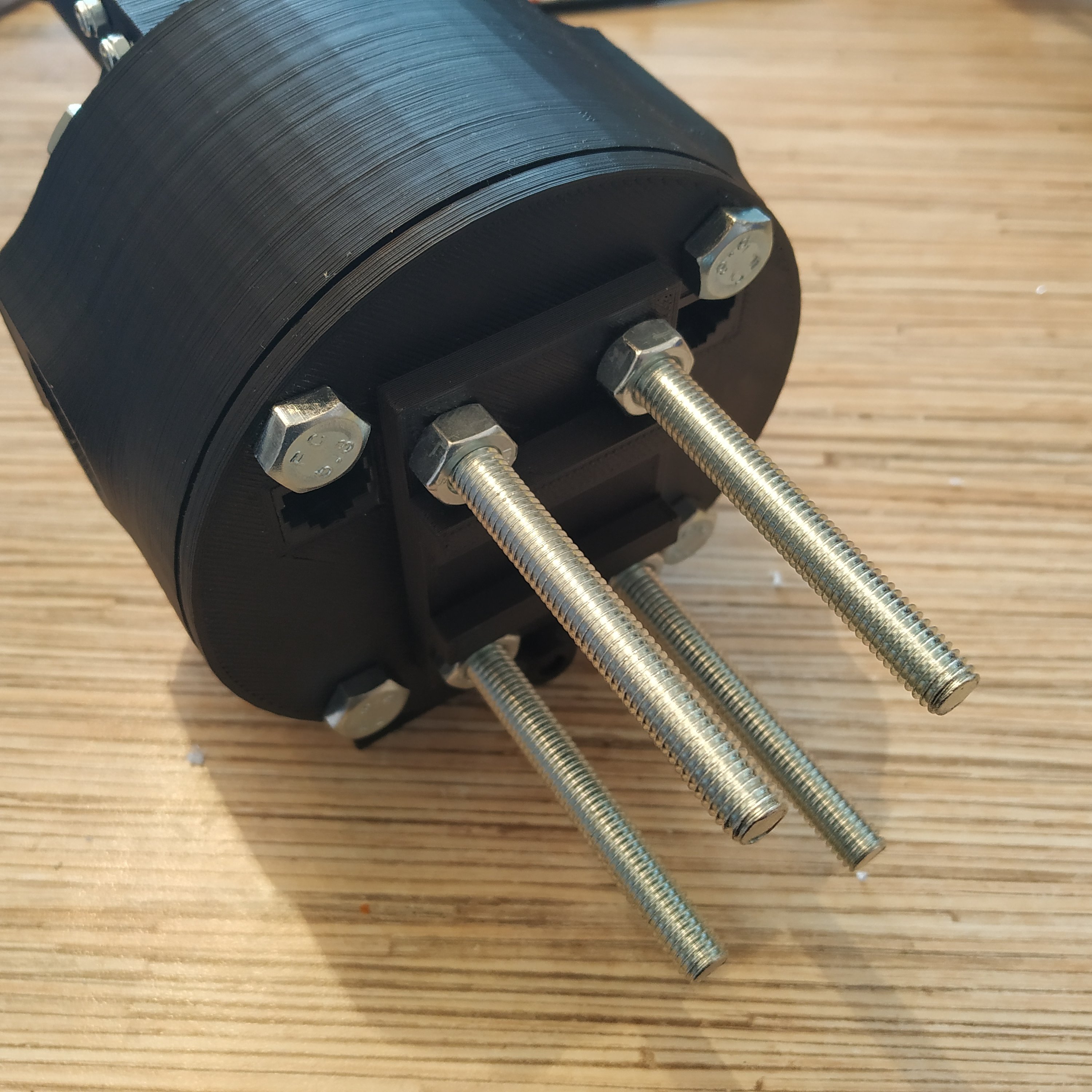
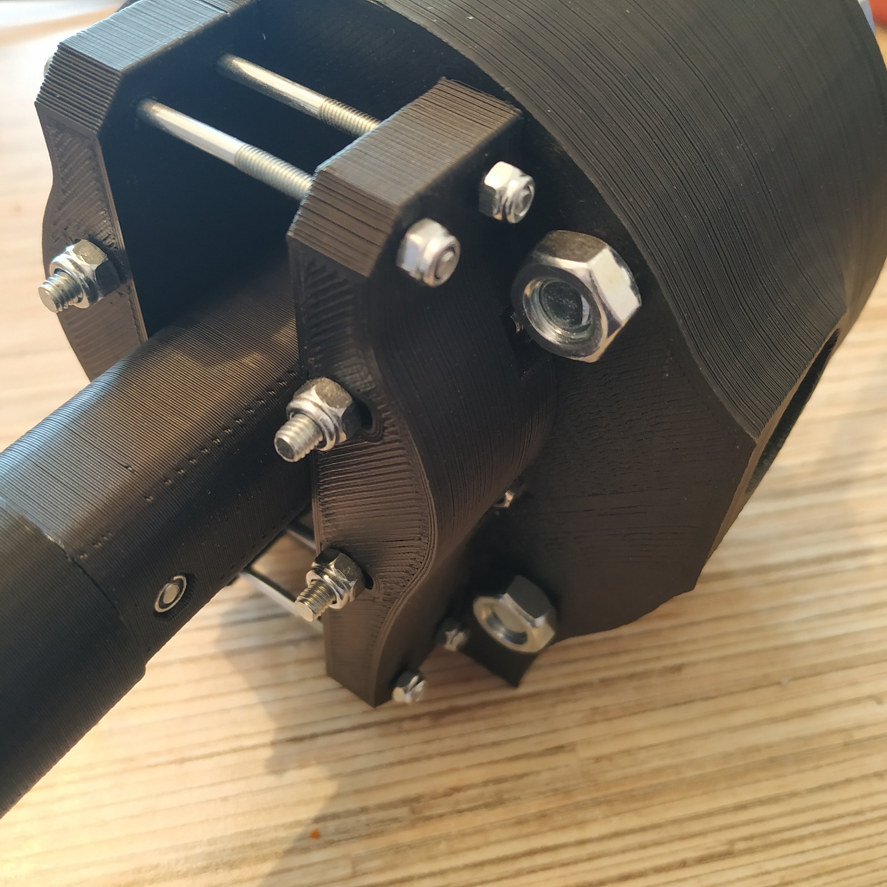
37. Add remaining parts of the housing: pneumatics mount and side covers. Congratulations, the base is finished!
