This is an old revision of the document!
Table of Contents
Simchair MKIV simple collective integrated head


Components
- 1 x 10x10mm aluminum square pipe (200mm length for single throttle)
- 1 x SS495A1 hall sensor
- 1 x MTS-103 ON-OFF-ON switch
- 1 x 6x6x4mm square magnet (or 5x5x5mm)
- 1 x M6x70mm screw
- 2 x M6 washers (reinforced)
- 1 x M6 nut
- 2 x M6x18x8mm hubs
- 6 x M4x40mm screws
- 4 x M4x70mm screws
- 1 x M3x20mm screw (round head)
- 1 x M3 nyloc nut
- 4 x M4 nyloc nuts
- 4 x M3x50mm screws for tensioner halves contraction
- 4 x M8x70 bolts
- 4 x M8x75mm bolts
- 8 x M8 nuts
- 10 x M8 washers (regular, non-reinforced)
- 4 x M8 spring washers
- 1 x bag of M4 nuts
- 4 x 608 bearings (standard skateboard bearings)
- 1 x Arduino Pro mini
- 1 x Simchair MKIV Master controller
- 2 x TJ8P8C Ethernet sockets (12,5x15x17,6mm)
- 1 x 6*6×17 mm tactile button
- super glue (cyanoacrylate), hot glue gun
Repository path
simchair4_models\printable components\peripherals\helicopter\collective lever\a_base - models
simchair4_software\peripherals - choose the preferred variant of the lever - software
Assembly Guide
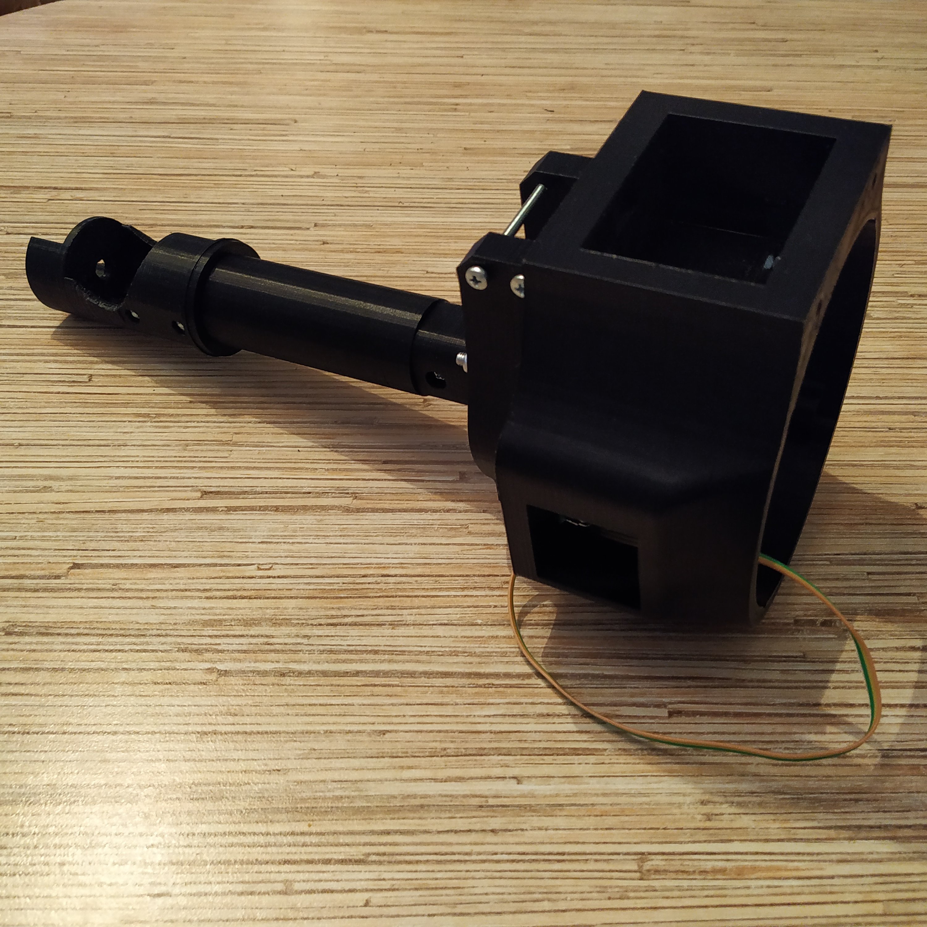
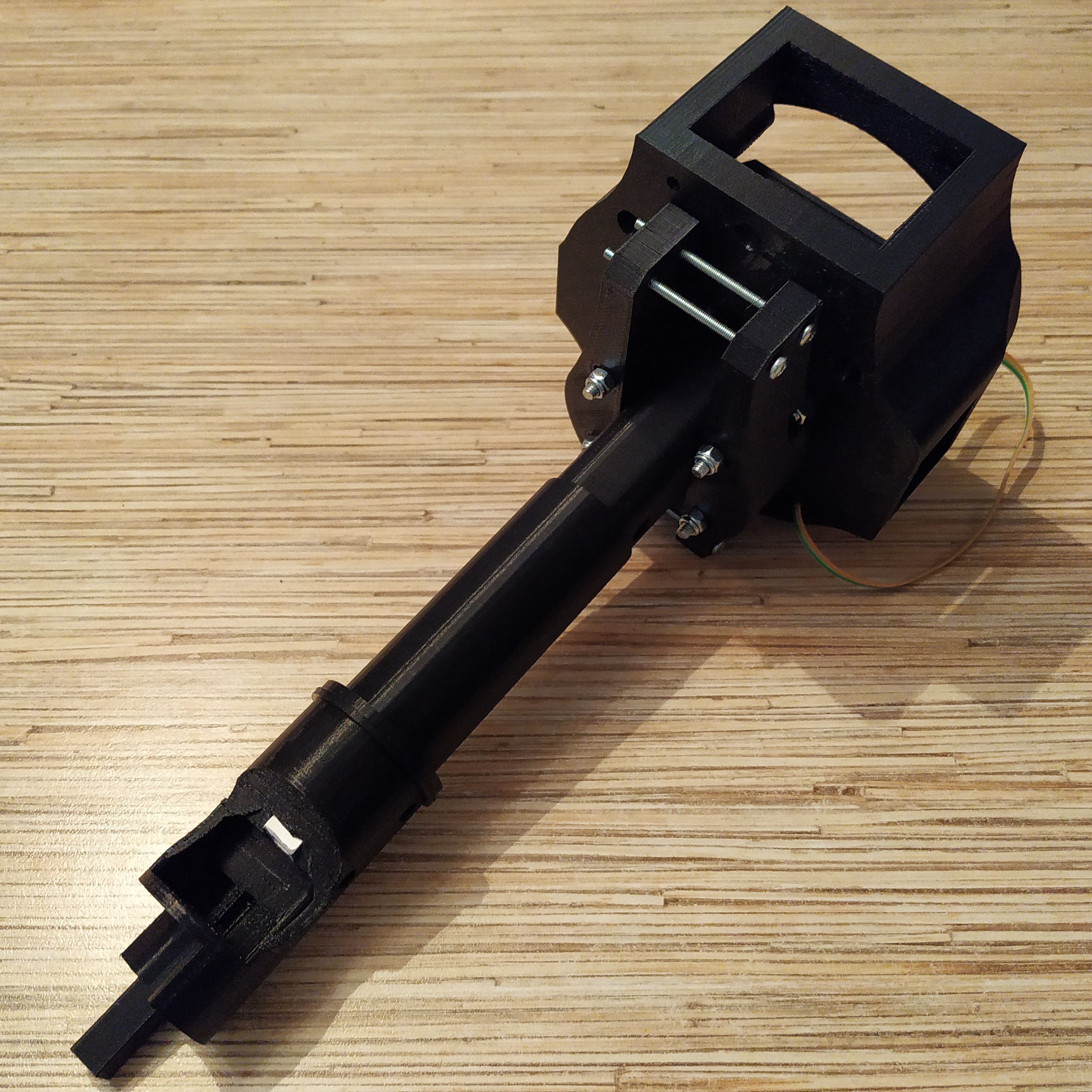
1. Assemble collective base up to the point shown on the pic below and install your preferred throttle frame p1 on it (in this guide I am using a 206-style lever throttle frame p1)
2. Install a throttle pot, the mode switch, and pull the pot cable and a 5-wire (!) cable through the lever.
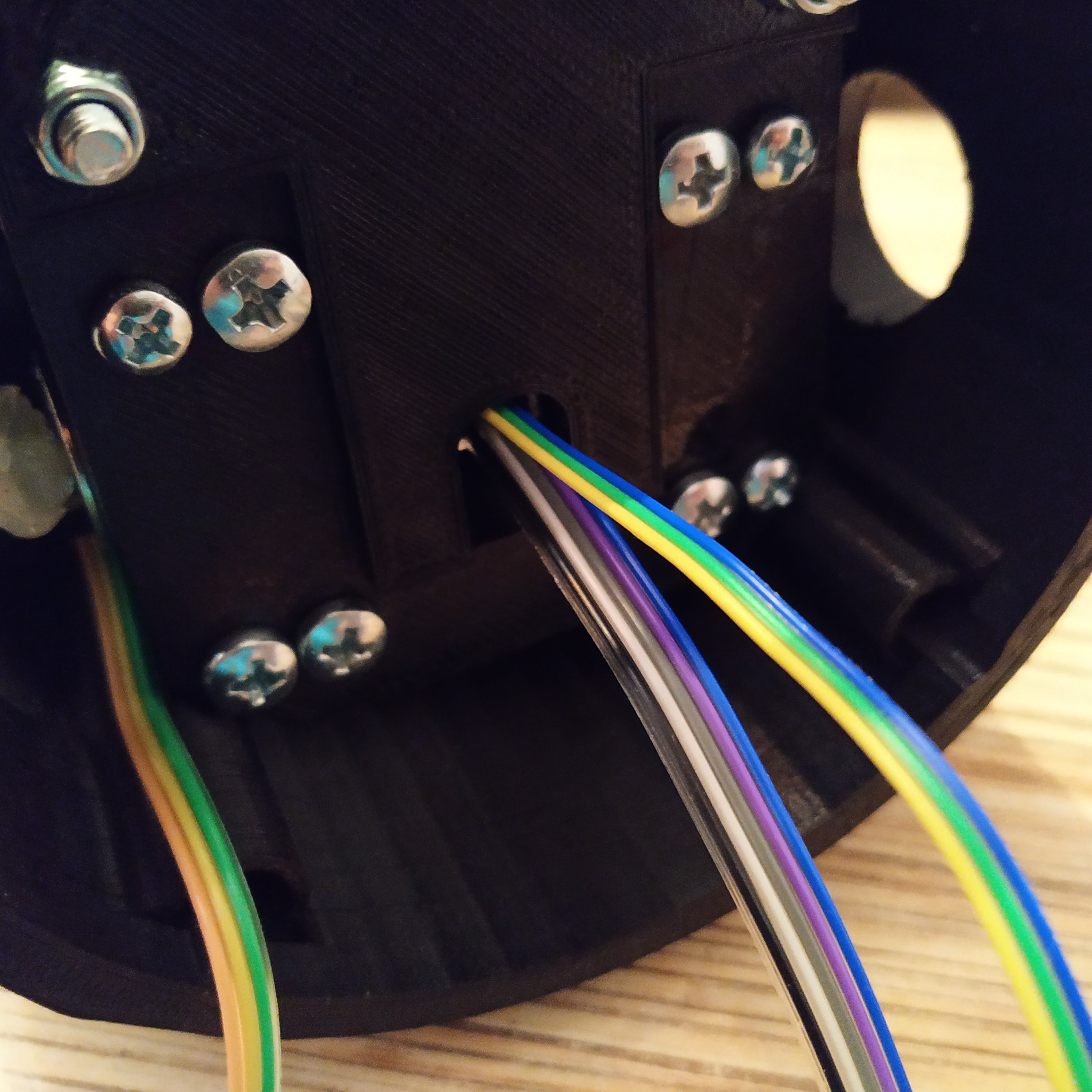
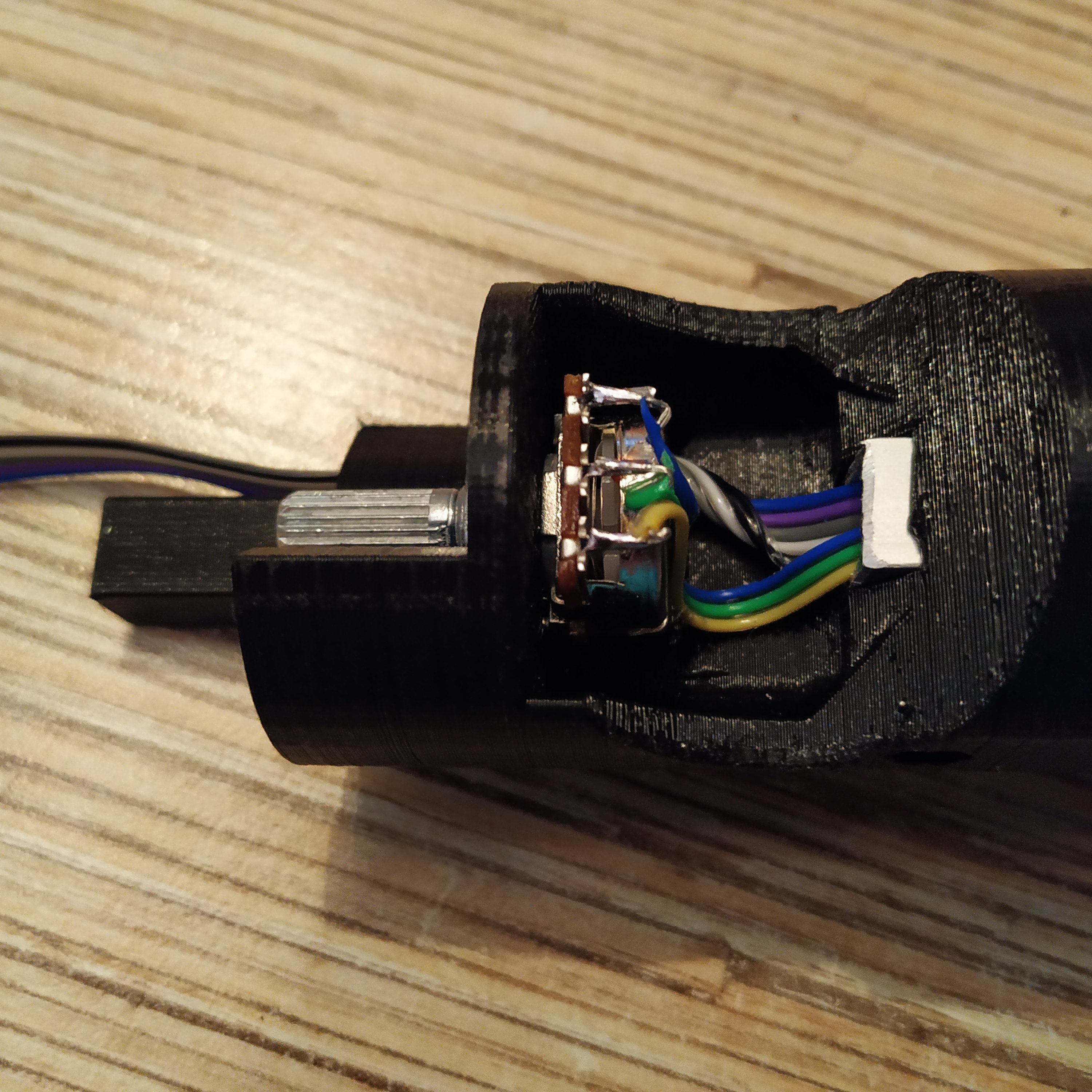
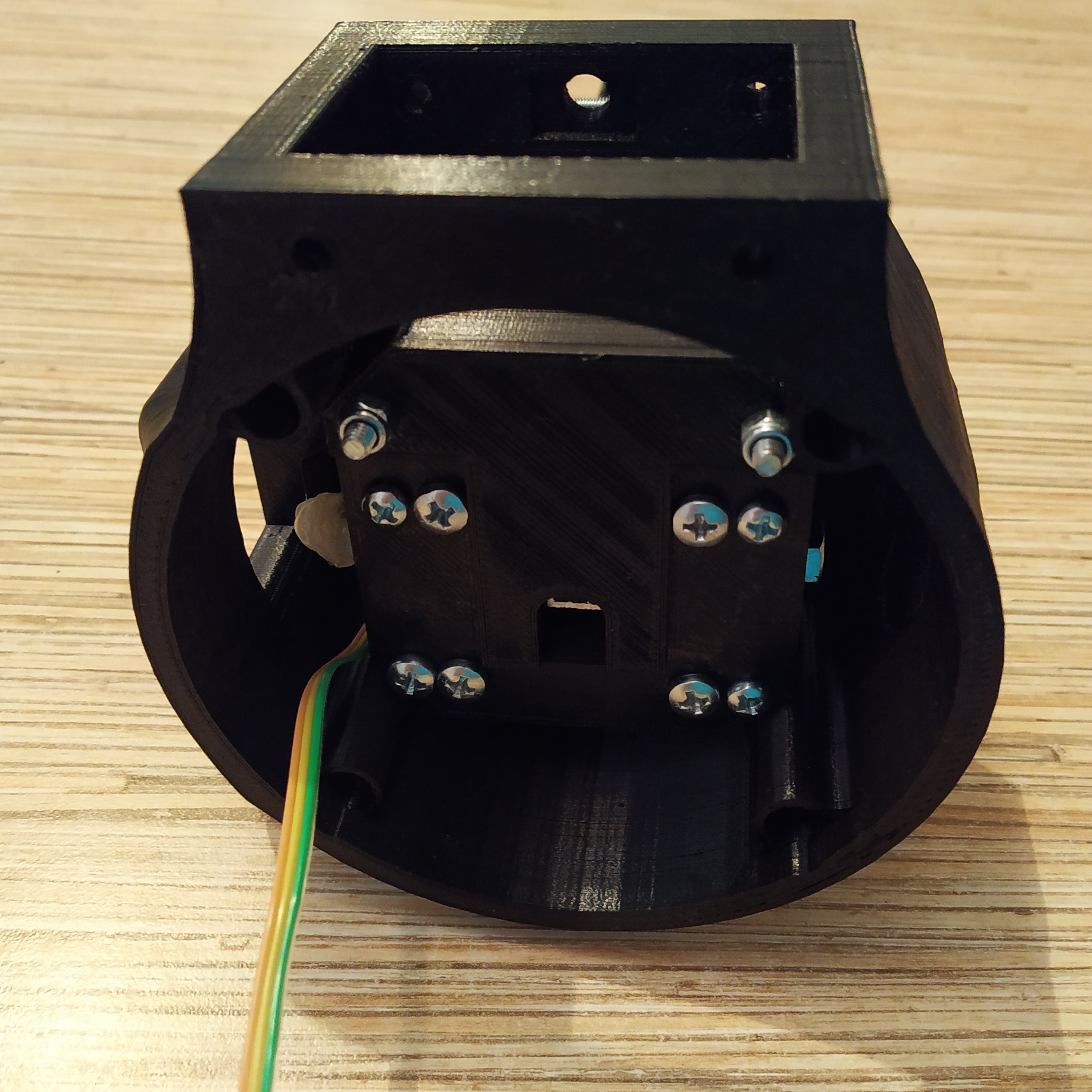
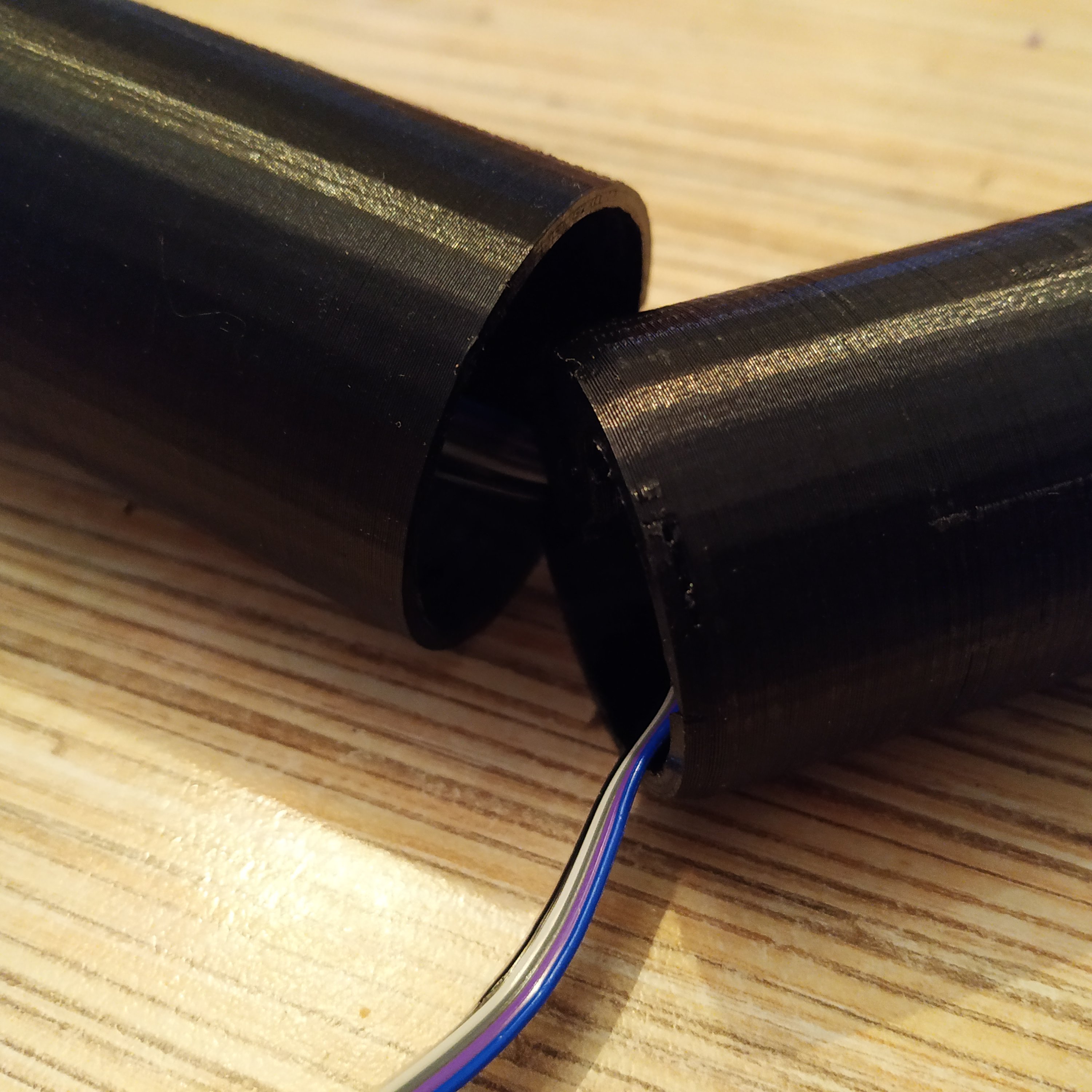
3. Turn the throttle pot fully left (full open collective as in Bell-206) and the slightly right to clear mechanical deadzone. Put the throttle grip on. Route the 5-wire cable through the cable channel in the the integrated head piece.
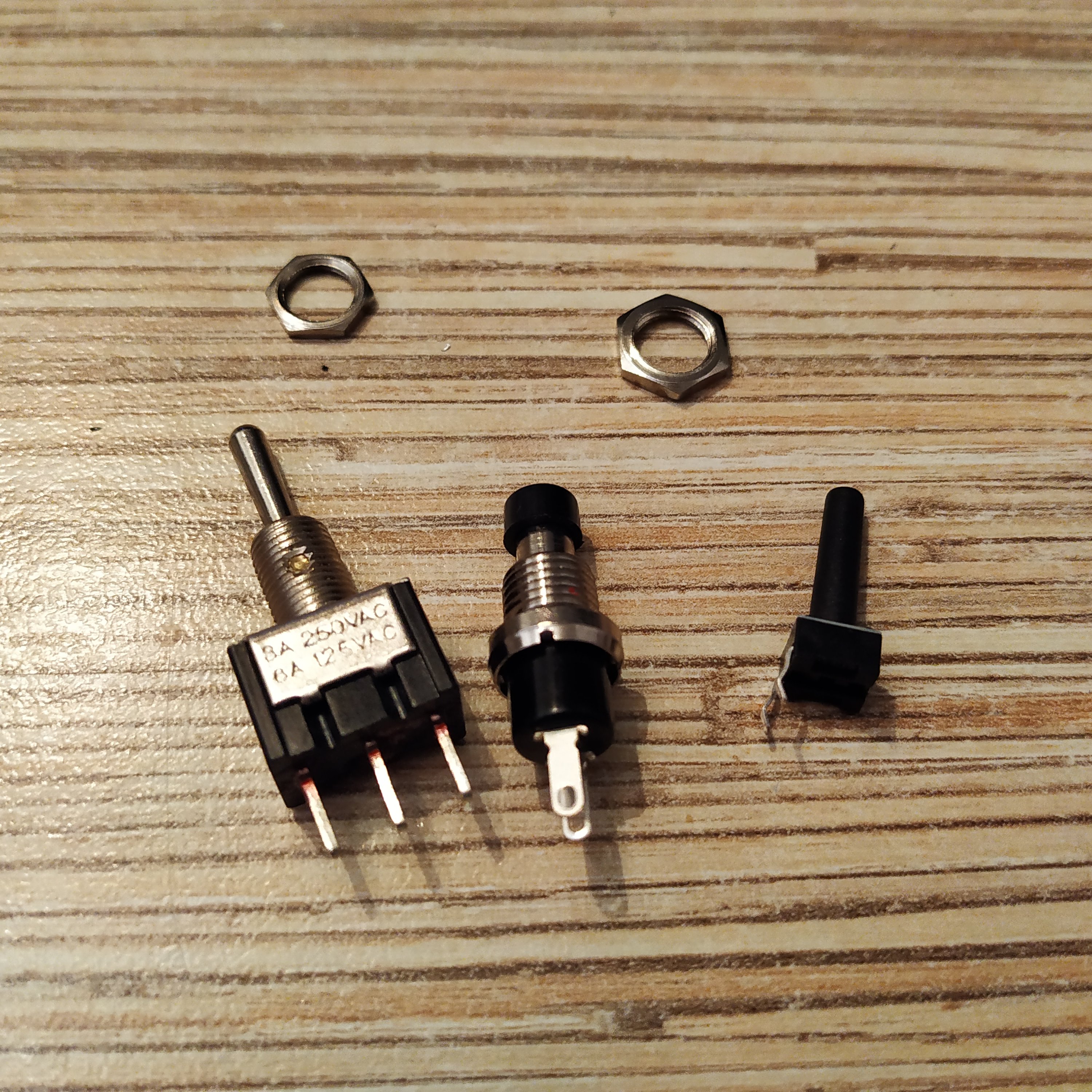
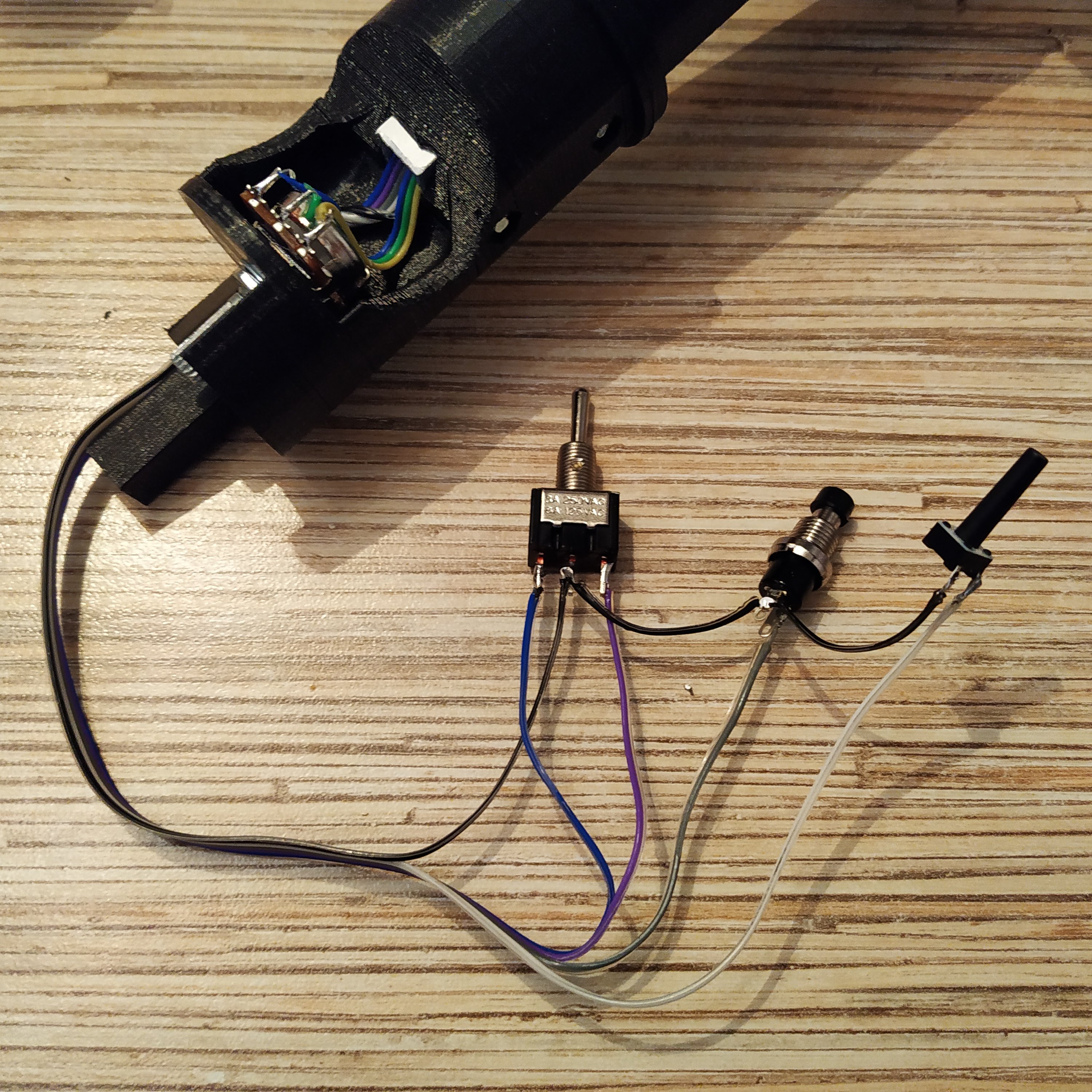
3. Prepare an MTS-123 switch, a 6x6x17mm tact button and a PBS-10-B2 button. Solder a ground wire from a 5-wire cable to them as shown on the picture below. Choose the wire at one of the ends of the cable that has a darker color.
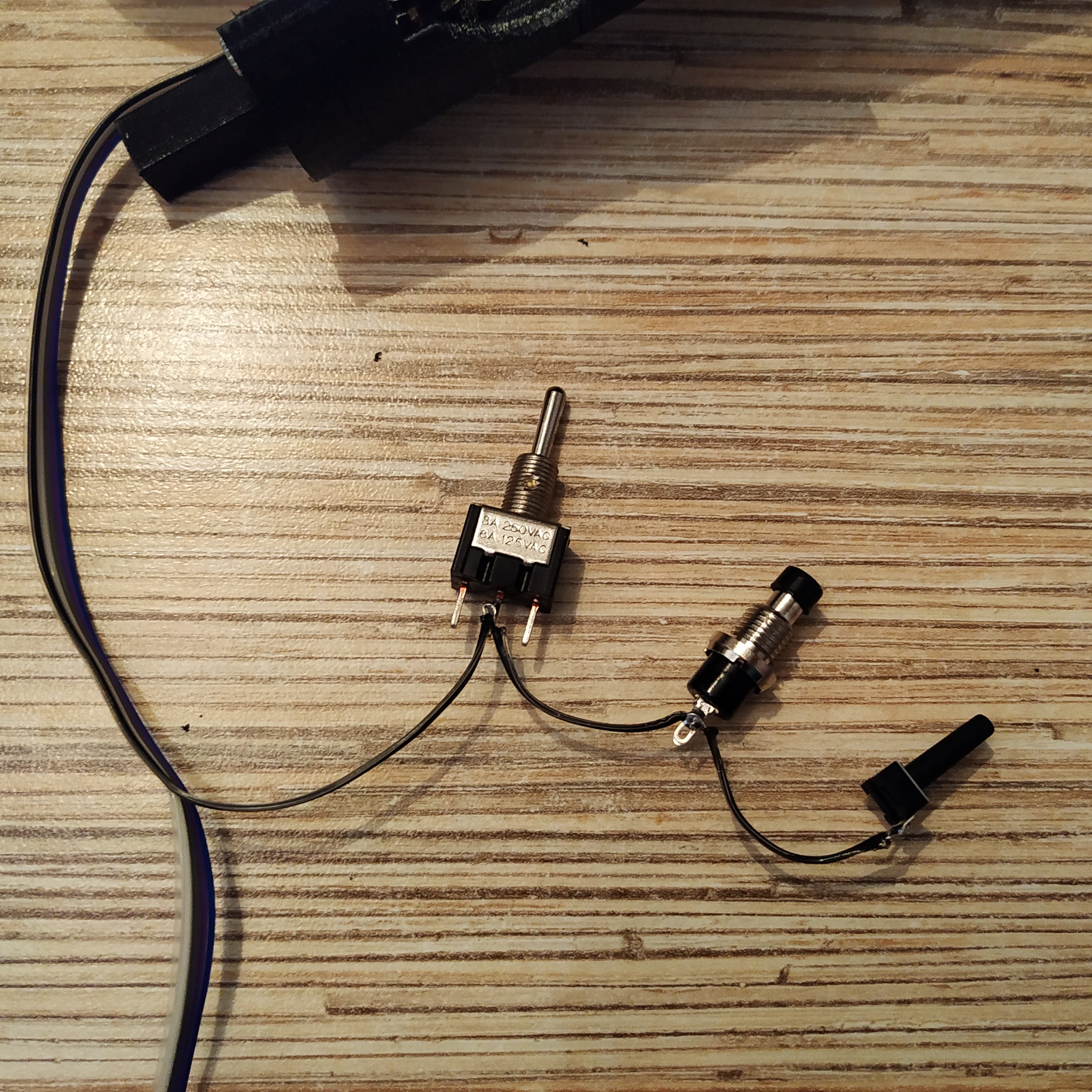
4. Solder other wires of a 5-wire cable. The ground wire is wire #1 in the ribbon:
1 → 6x6x17 mm tact button 2 → PBS-10B2 3 → MTS-123 switch right pin 4 → MTS-123 switch left pin
5. Put buttons and the switch to their sockets in thr frame p2
