This is an old revision of the document!
Table of Contents
Simchair MKIV simple collective integrated head


Components
- 1 x 10x10mm aluminum square pipe (200mm length for single throttle)
- 1 x SS495A1 hall sensor
- 1 x MTS-103 ON-OFF-ON switch
- 1 x 6x6x4mm square magnet (or 5x5x5mm)
- 1 x M6x70mm screw
- 2 x M6 washers (reinforced)
- 1 x M6 nut
- 2 x M6x18x8mm hubs
- 6 x M4x40mm screws
- 4 x M4x70mm screws
- 1 x M3x20mm screw (round head)
- 1 x M3 nyloc nut
- 4 x M4 nyloc nuts
- 4 x M3x50mm screws for tensioner halves contraction
- 4 x M8x70 bolts
- 4 x M8x75mm bolts
- 8 x M8 nuts
- 10 x M8 washers (regular, non-reinforced)
- 4 x M8 spring washers
- 1 x bag of M4 nuts
- 4 x 608 bearings (standard skateboard bearings)
- 1 x Arduino Pro mini
- 1 x Simchair MKIV Master controller
- 2 x TJ8P8C Ethernet sockets (12,5x15x17,6mm)
- 1 x 6*6×17 mm tactile button
- super glue (cyanoacrylate), hot glue gun
Repository path
simchair4_models\printable components\peripherals\helicopter\collective lever\a_base - models
simchair4_software\peripherals - choose the preferred variant of the lever - software
Assembly Guide
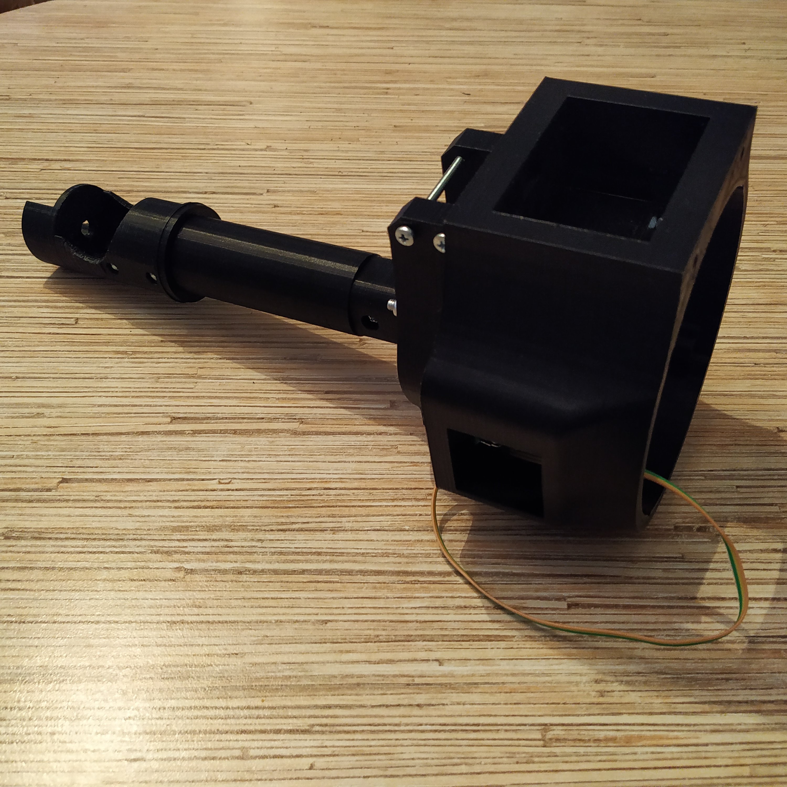
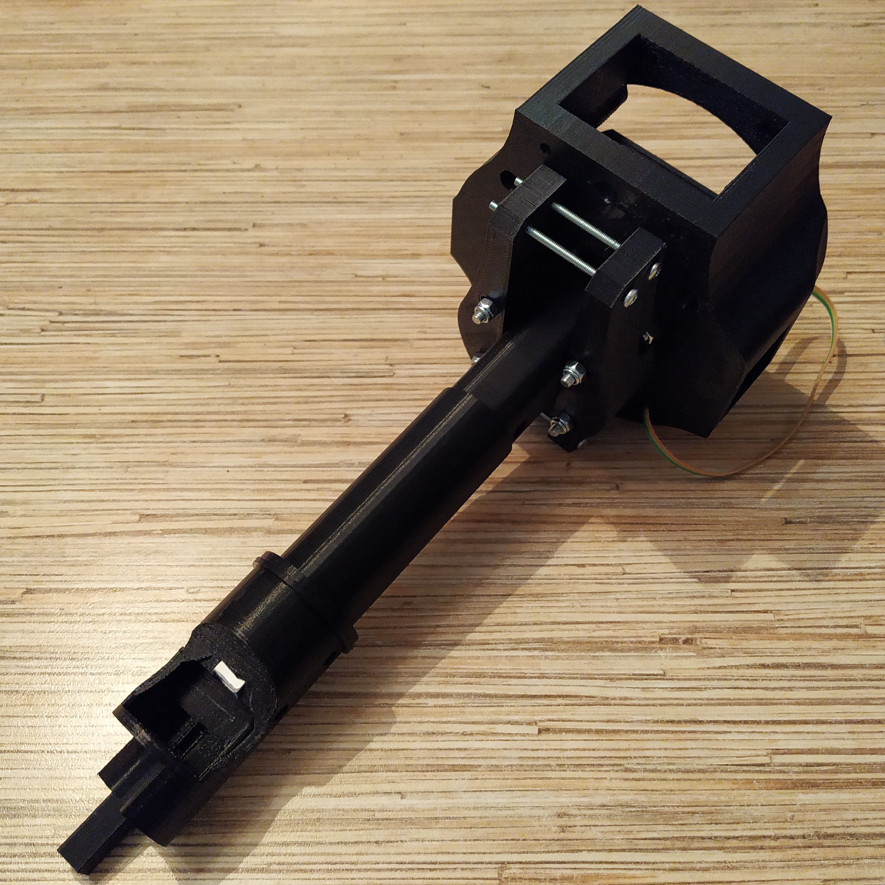
1. Assemble collective base up to the point shown on the pic below and install your preferred throttle frame p1 on it (in this guide I am using a 206-style lever throttle frame p1)
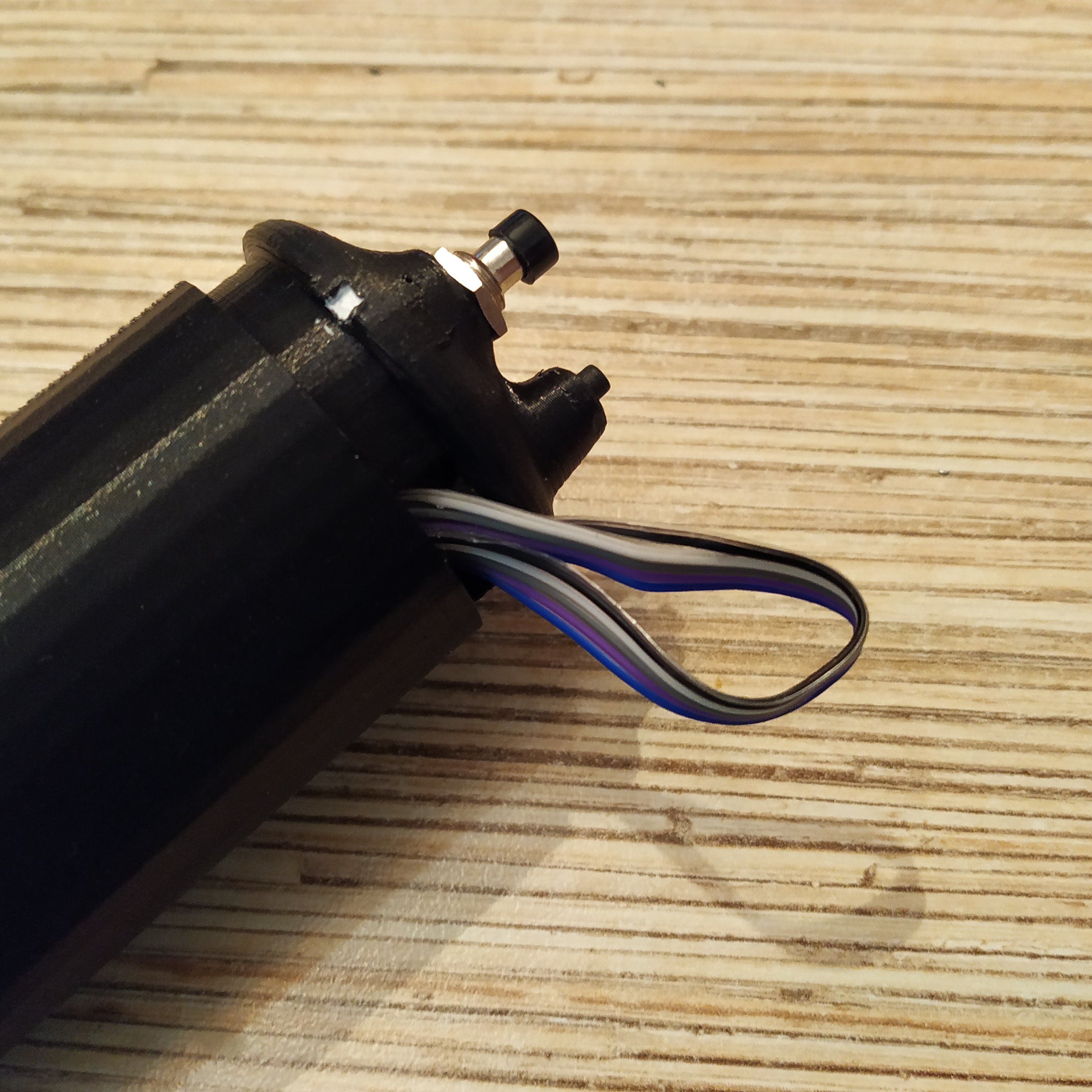
2. Install a throttle pot, the mode switch, and pull the pot cable and a 5-wire (!) cable through the lever.
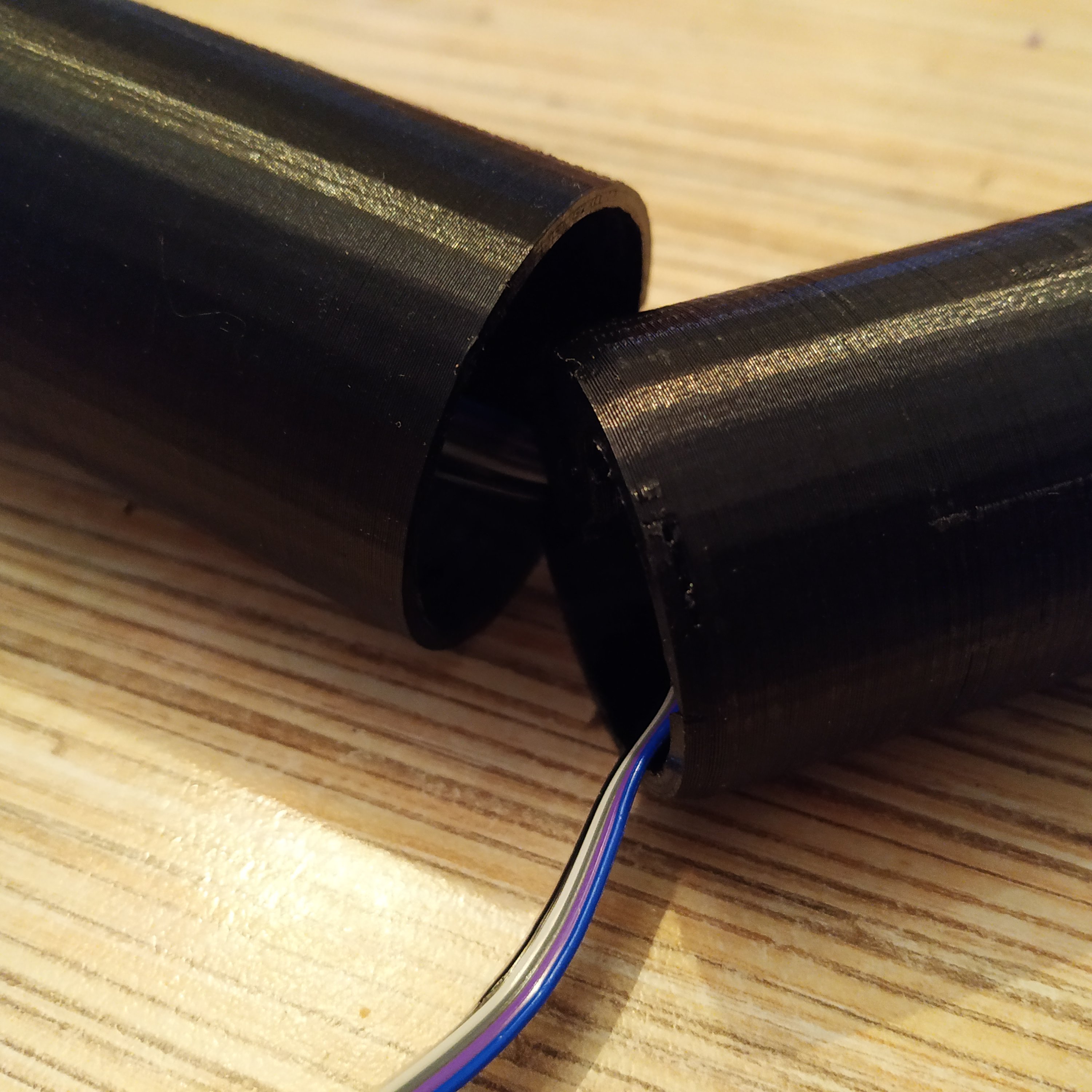
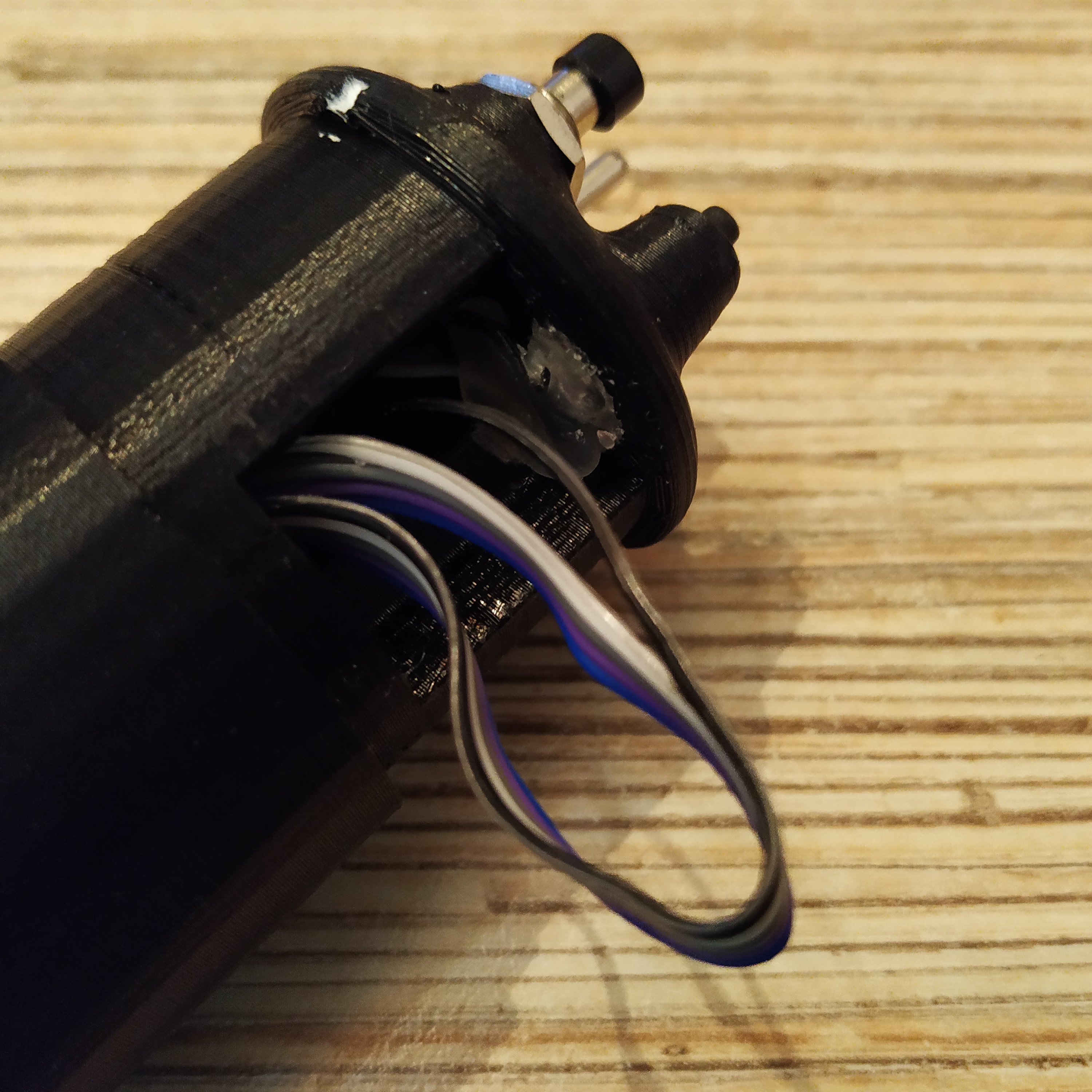
3. Turn the throttle pot fully left (full open collective as in Bell-206) and the slightly right to clear mechanical deadzone. Put the throttle grip on. Route the 5-wire cable through the cable channel in the the integrated head piece.
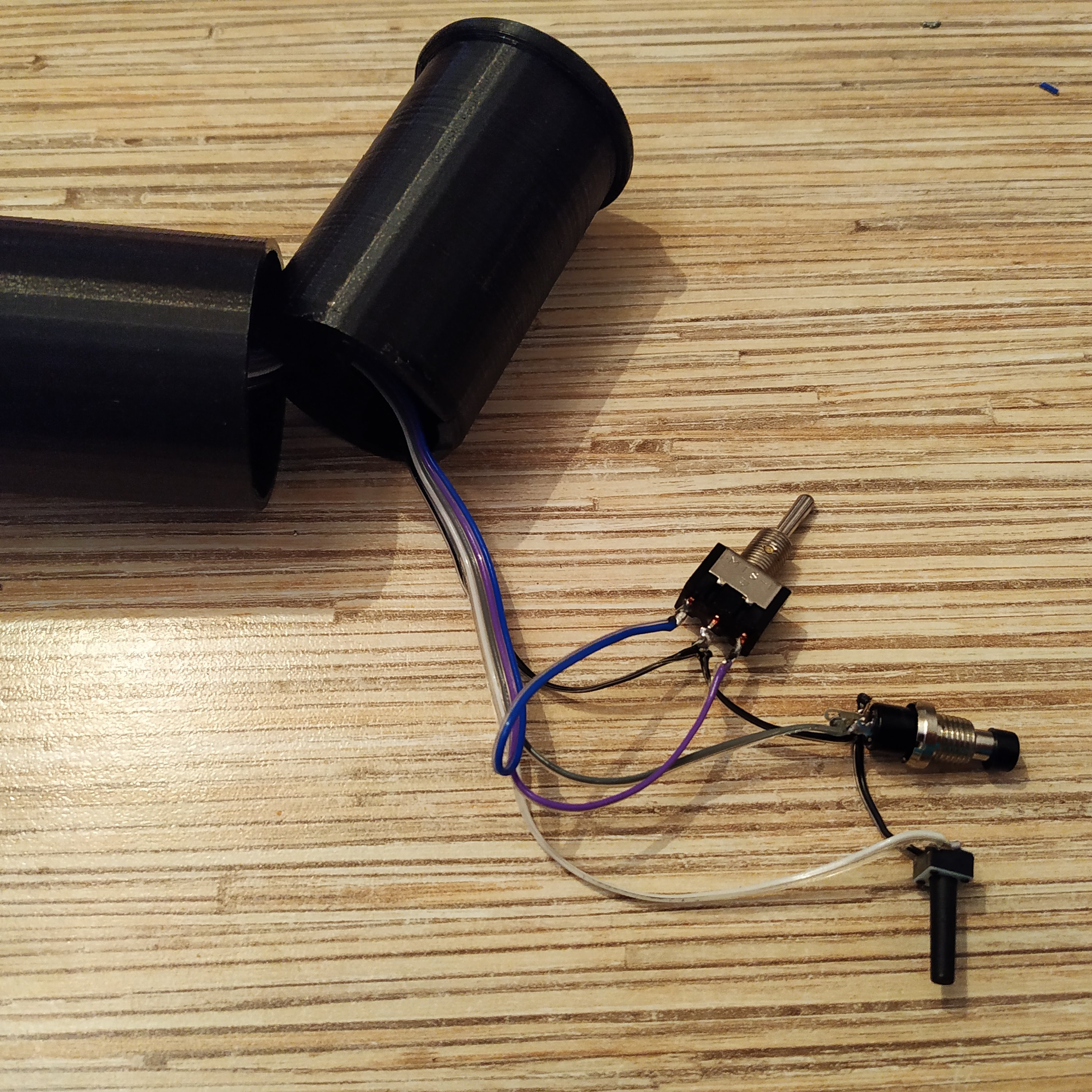
4. Prepare an MTS-123 switch, a 6x6x17mm tact button and a PBS-10-B2 button. Solder a ground wire from a 5-wire cable to them as shown on the picture below. Choose the wire at one of the ends of the cable that has a darker color.
5. Solder other wires of a 5-wire cable. The ground wire is wire #1 in the ribbon:
1 → GND 2 → 6x6x17 mm tact button 3 → PBS-10B2 4 → MTS-123 switch right pin 5 → MTS-123 switch left pin
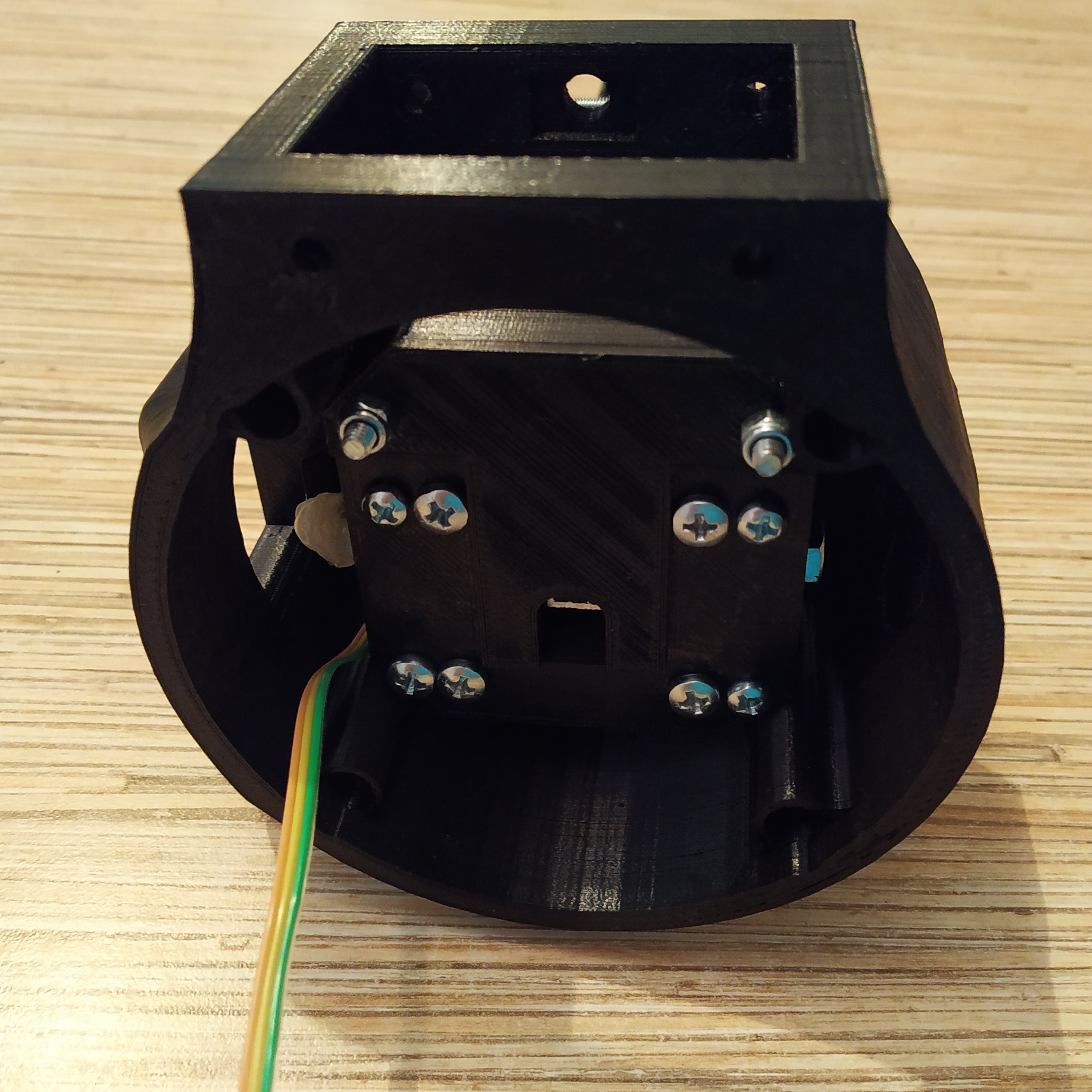
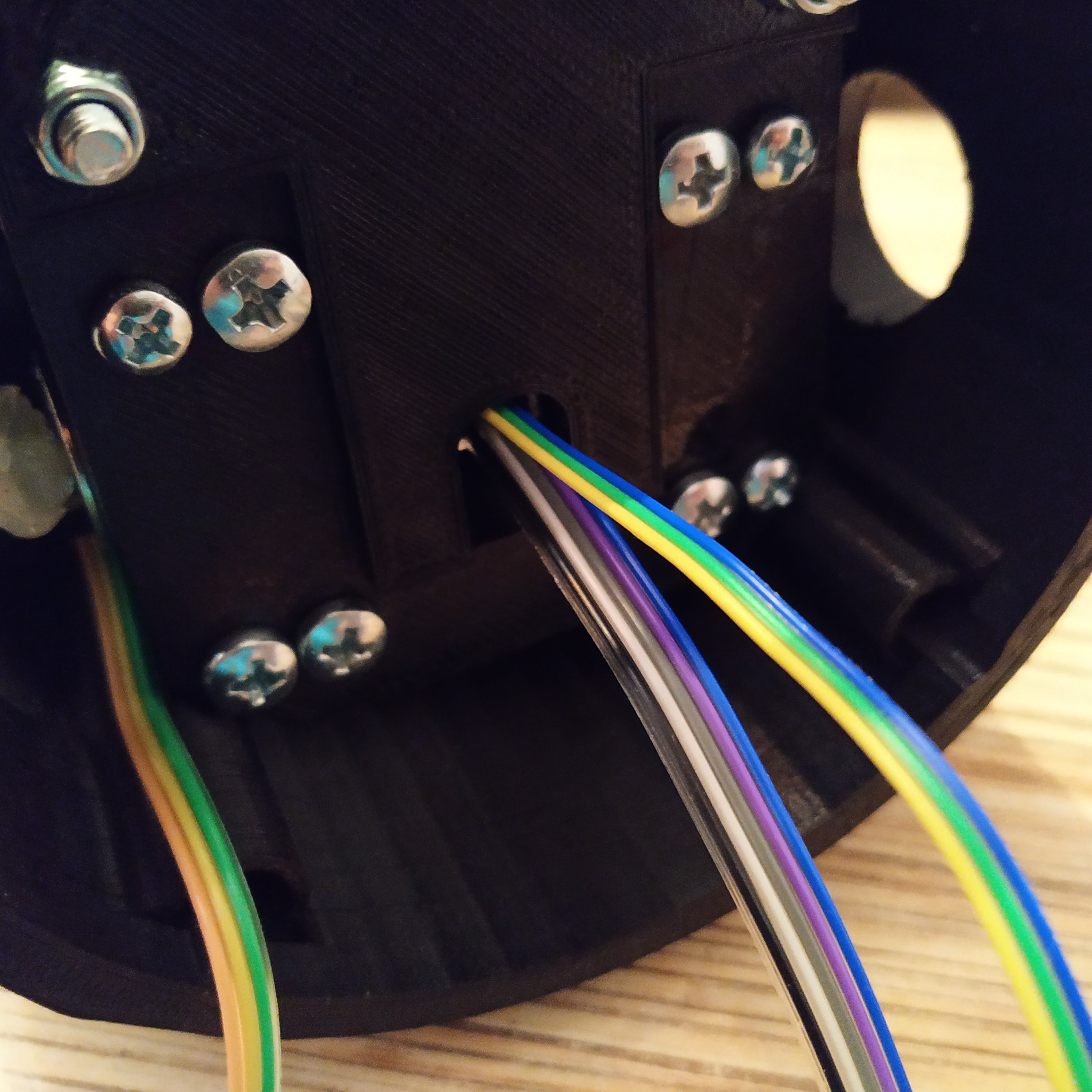
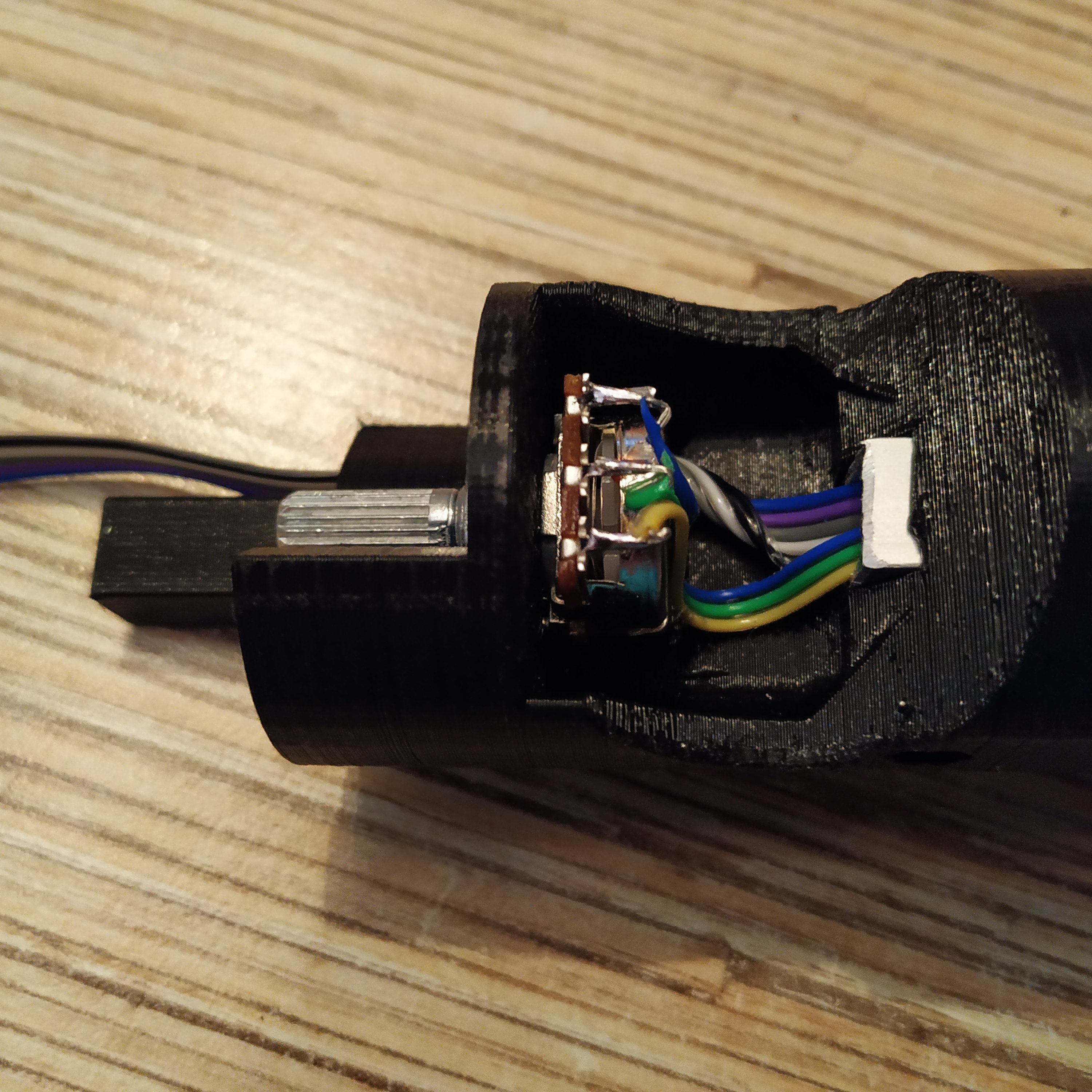
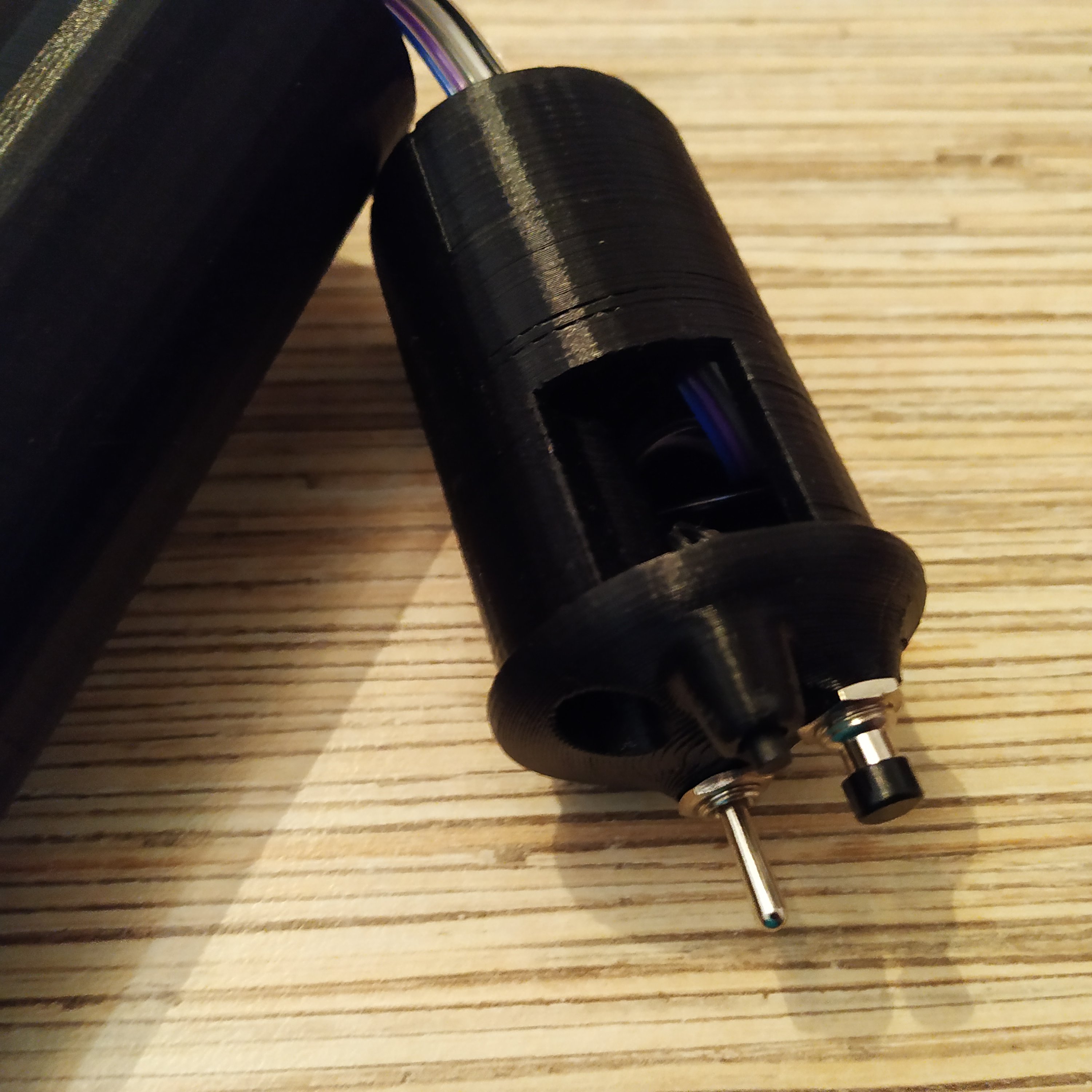
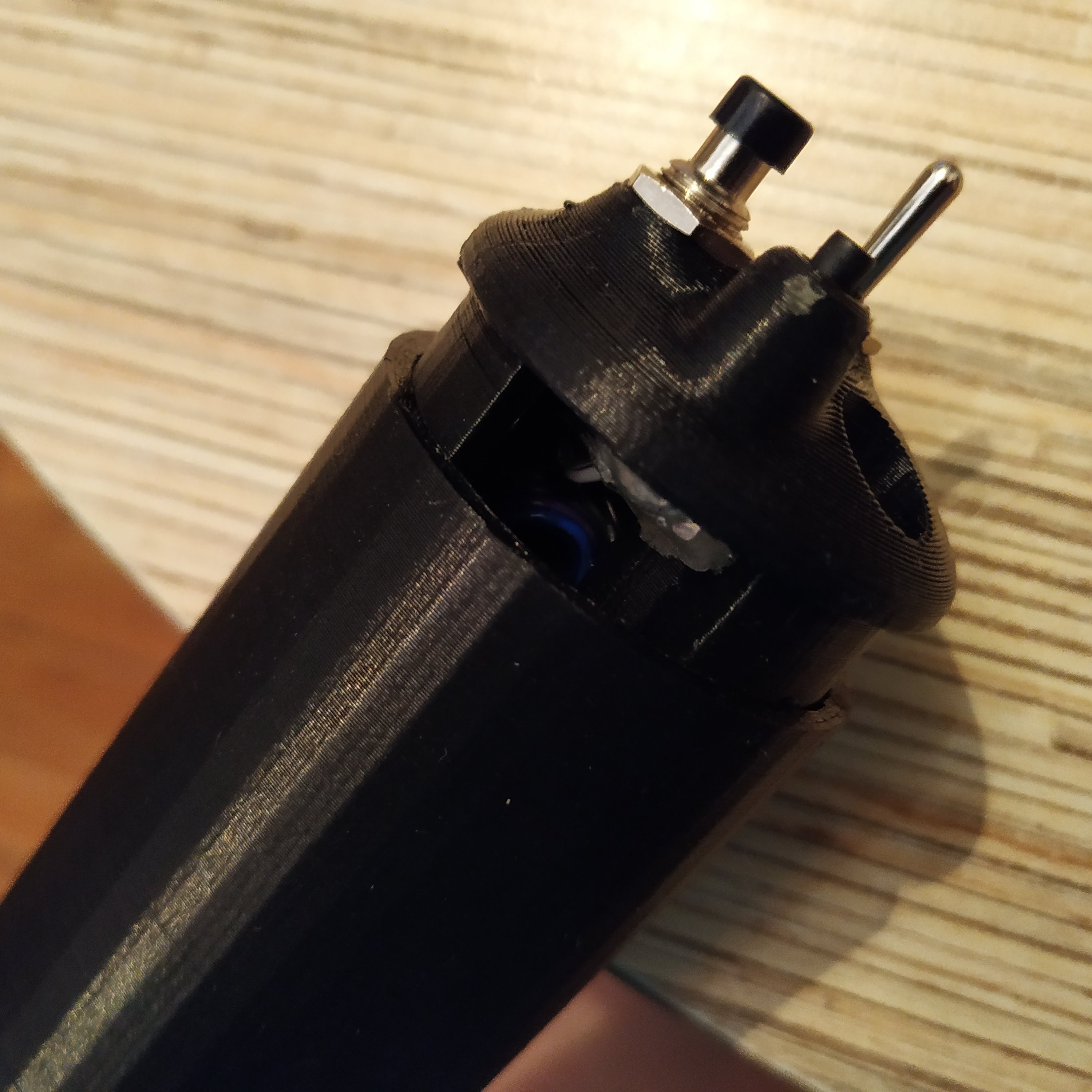
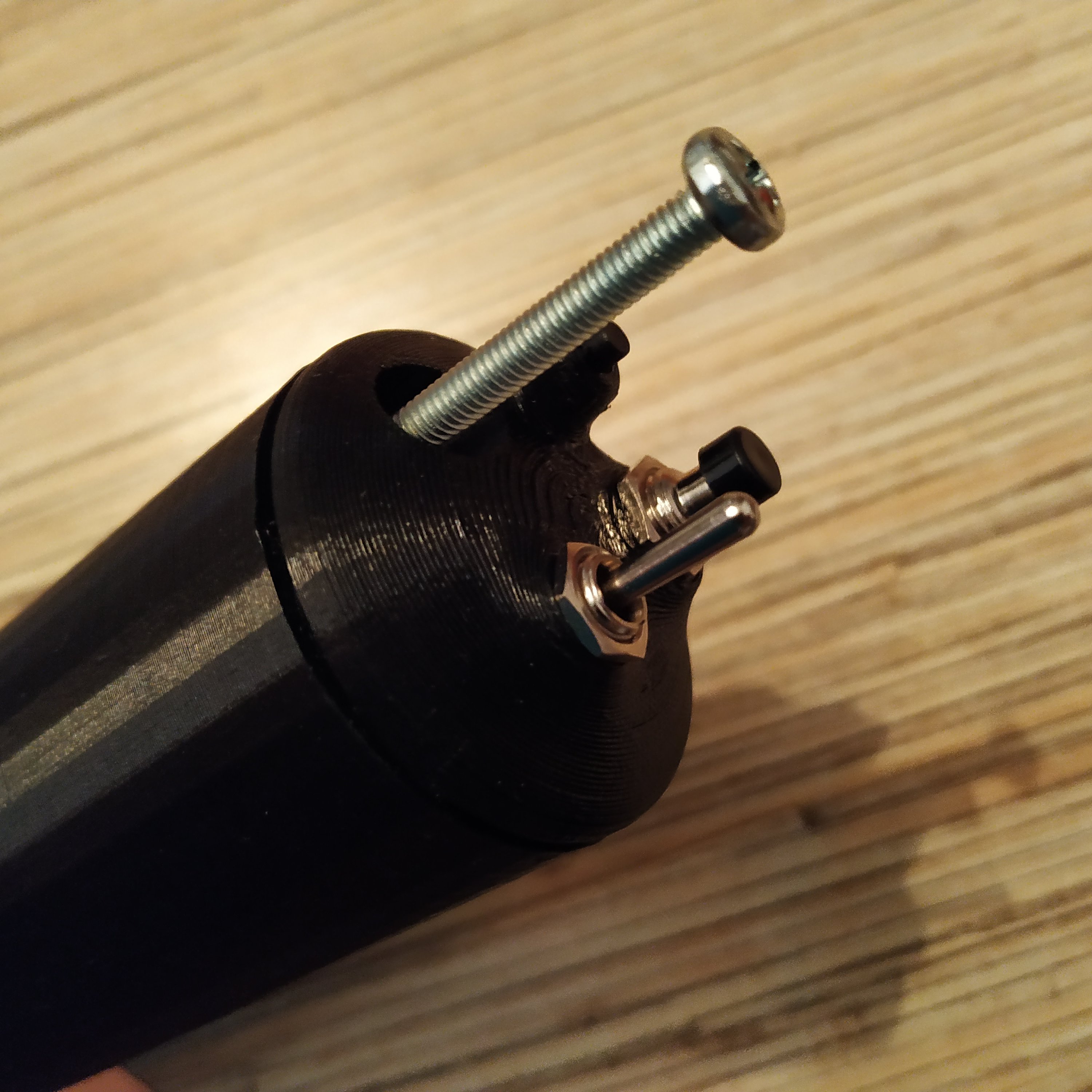
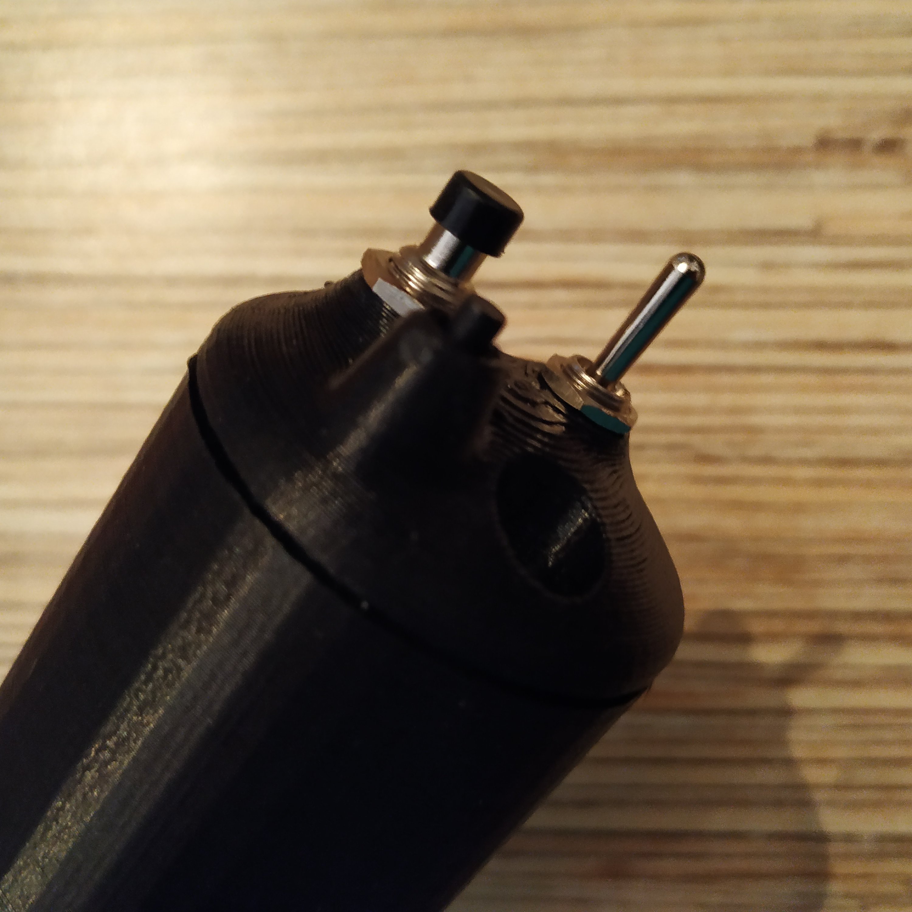
5. Fit buttons and the switch into their sockets in the head. Use pliers, screwdrivers, etc to accomplish that. Glue the tact button with some hot glue. Pull the 5-wire cable in a management window as shown in the corresponding picture below.
6. Press-fit the head onto thr frame p1 while simultaneously pulling the cable until there's just enough space to fit it into the head. Pack it into the head so it wont touch the rotating grip and press-fit the grip completely.
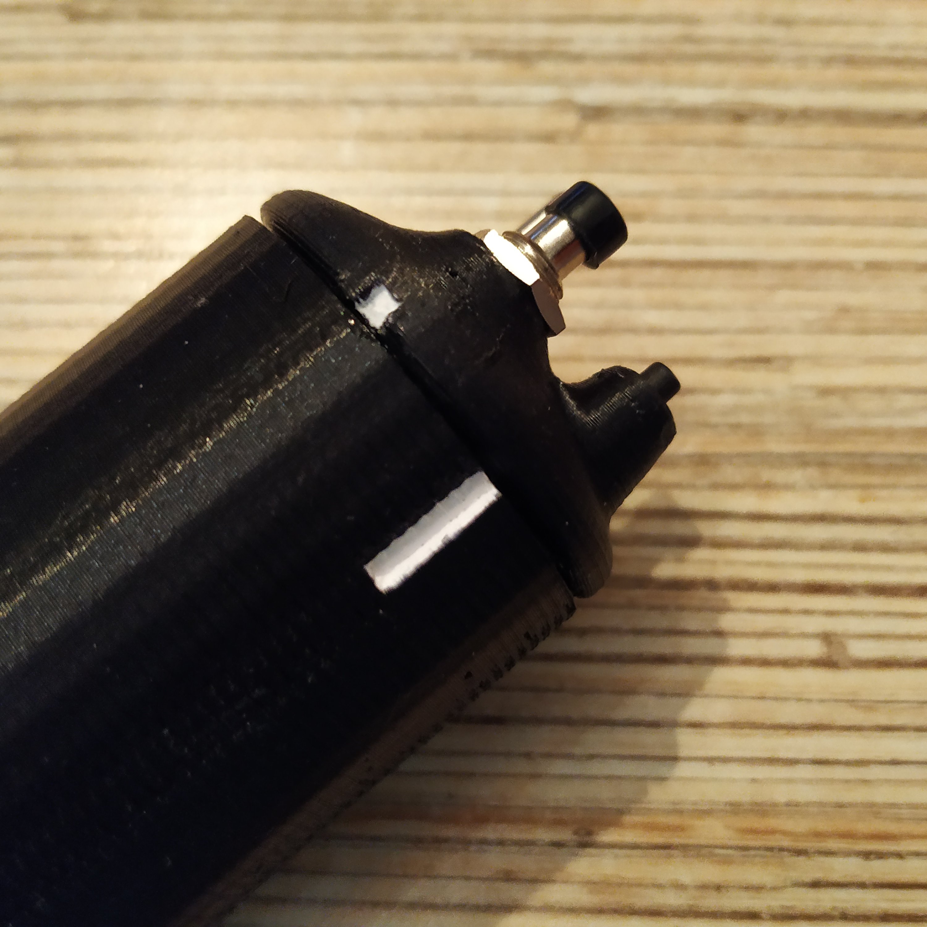
7. Put an M4x80mm screw into its socket in the head.
8. Finish wiring the base according to its manual, with one exception - connect the head to the Pro Mini of the base as described below. I will refer to 5 wire ribbon cable of the head as “head cable”, and wire 1 as a GND wire.
HEAD CABLE WIRE 1 → GND HEAD CABLE WIRE 2 → PIN4 HEAD CABLE WIRE 3 → PIN5 HEAD CABLE WIRE 4 → PIN6 HEAD CABLE WIRE 5 → PIN7
That's it, you have built yourself a very nice, easy to service, compact lever. For total awesomeness, consider adding a pedestal!
