Table of Contents
Simchair MKIV simple collective integrated head Second Edition
Summary
This collective lever is an awesome thing in its own way – beautiful in its minimalism, inexpensive, compact device that still supports all MKIV features, sporting an 8-way hat switch, that is mapped to a total of 24 buttons when used with MKIV base mode switch, and support for multiple throttle axes (2 at the moment) with MKIV EVO throttle mode switch. It supports advanced throttle features (software idle-stop detent) and can be operated with or without the pneumatic mod. It’s also very portable and can be used with motion platforms. You can also fit MKIV base extensions (pedestals at the moment) onto this lever, enabling you to control switches and knobs in your virtual cockpit with your left hand, which is especially useful in VR!
This is a perfect device for helicopter enthusiasts that have limited space in their sim pit or want an inexpensive but feature-rich device. It has enough buttons to fly pretty much anything unless you want it for combat and need more switches, particularly on the collective head. In this case, look at the MKIV compact collective with an integrated head!
Components
1 x MKIV collective EVO base (pick USB or I2C version)
1 x MKIV simple collective SE lever body
2 x 10mm hat switch (one spare for hat switch cap fitting)
ribbon cable
hot glue
Repository path
simchair4_models\printable components\peripherals\helicopter\collective lever\c_switch panels\simple integrated head se - models
simchair4_software\peripherals\collective_simple_se - software (I2C version only, the USB version is flashed with the master software)
Assembly Guide
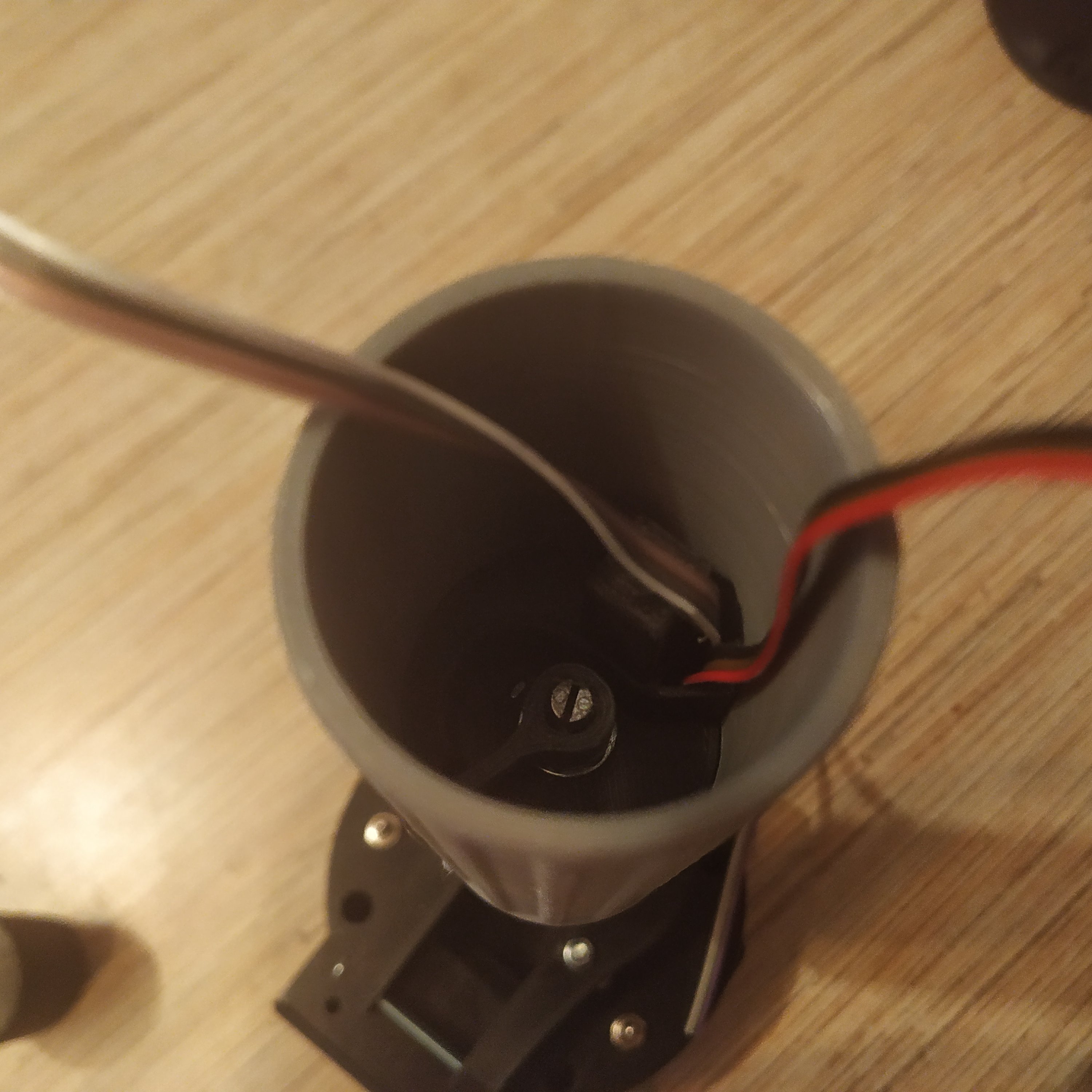
1. Assemble collective base and the lever body up to the point shown on the pic below (look at the Single throttle lever body for integrated heads manual but use parts from the simple collective SE body directory instead). Note that instead of the 4-wire I2C cable used in a regular lever, a 6-wire hat switch cable is inserted. Note the colors of the cable, the hat switch cable is strictly color-coded for ease of use.

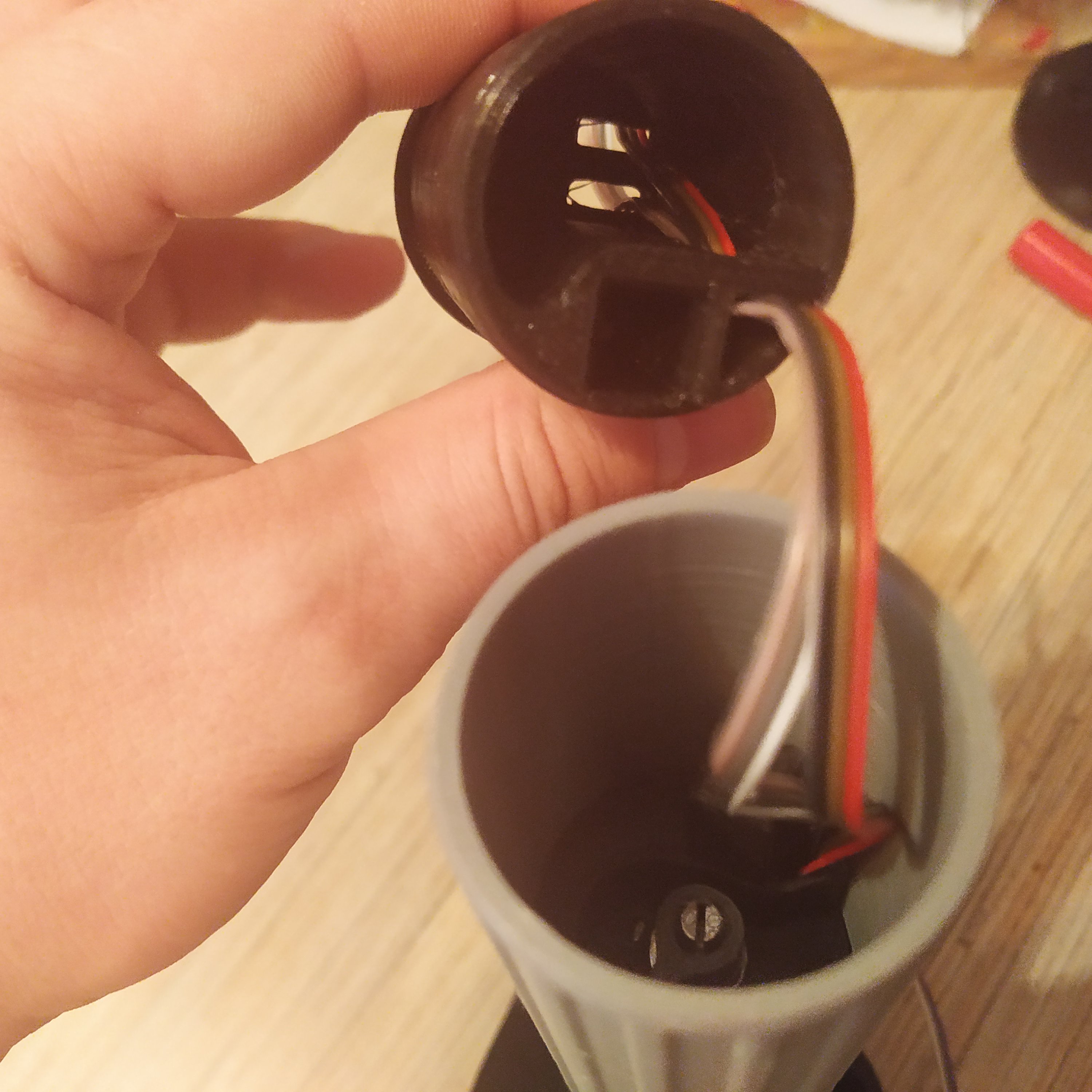
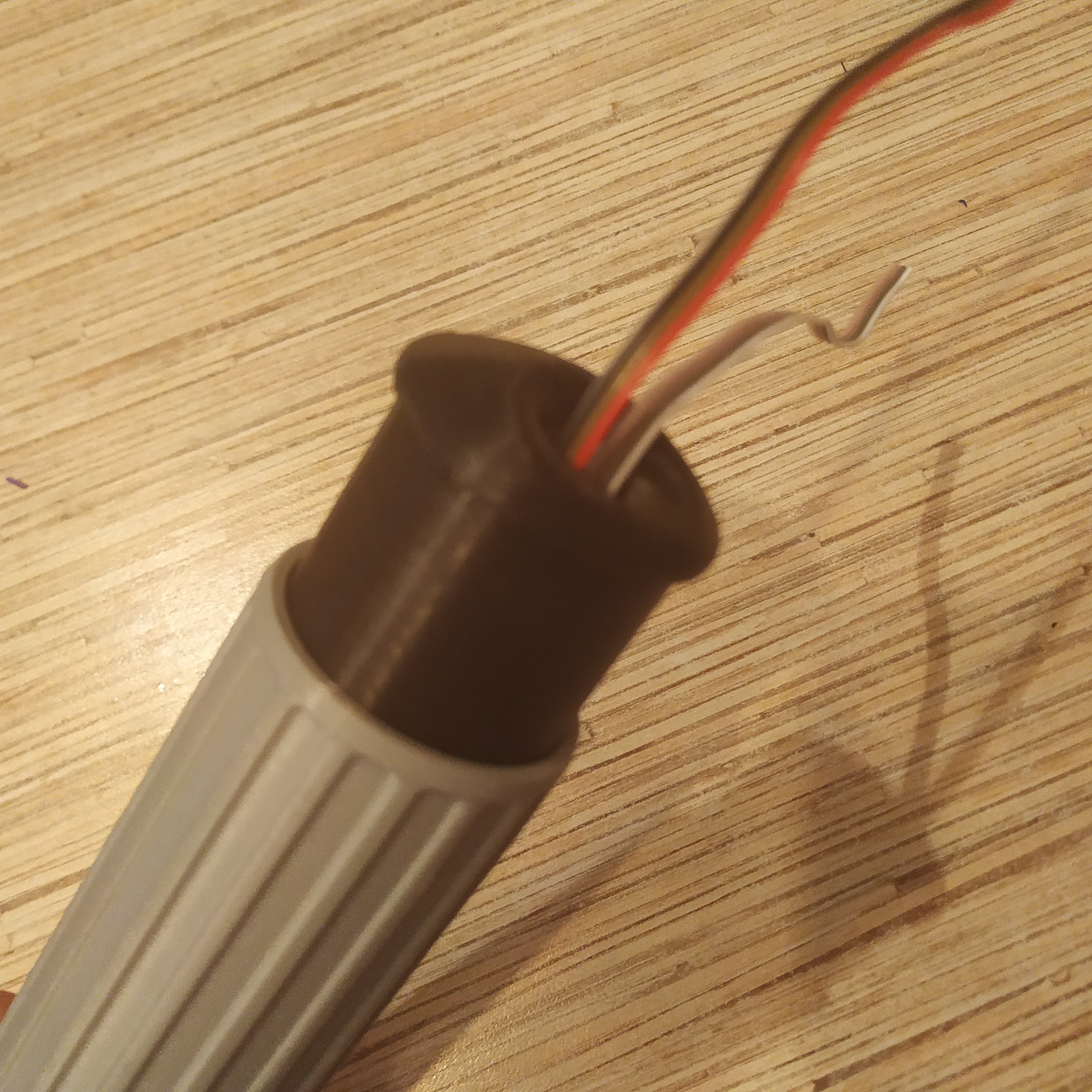
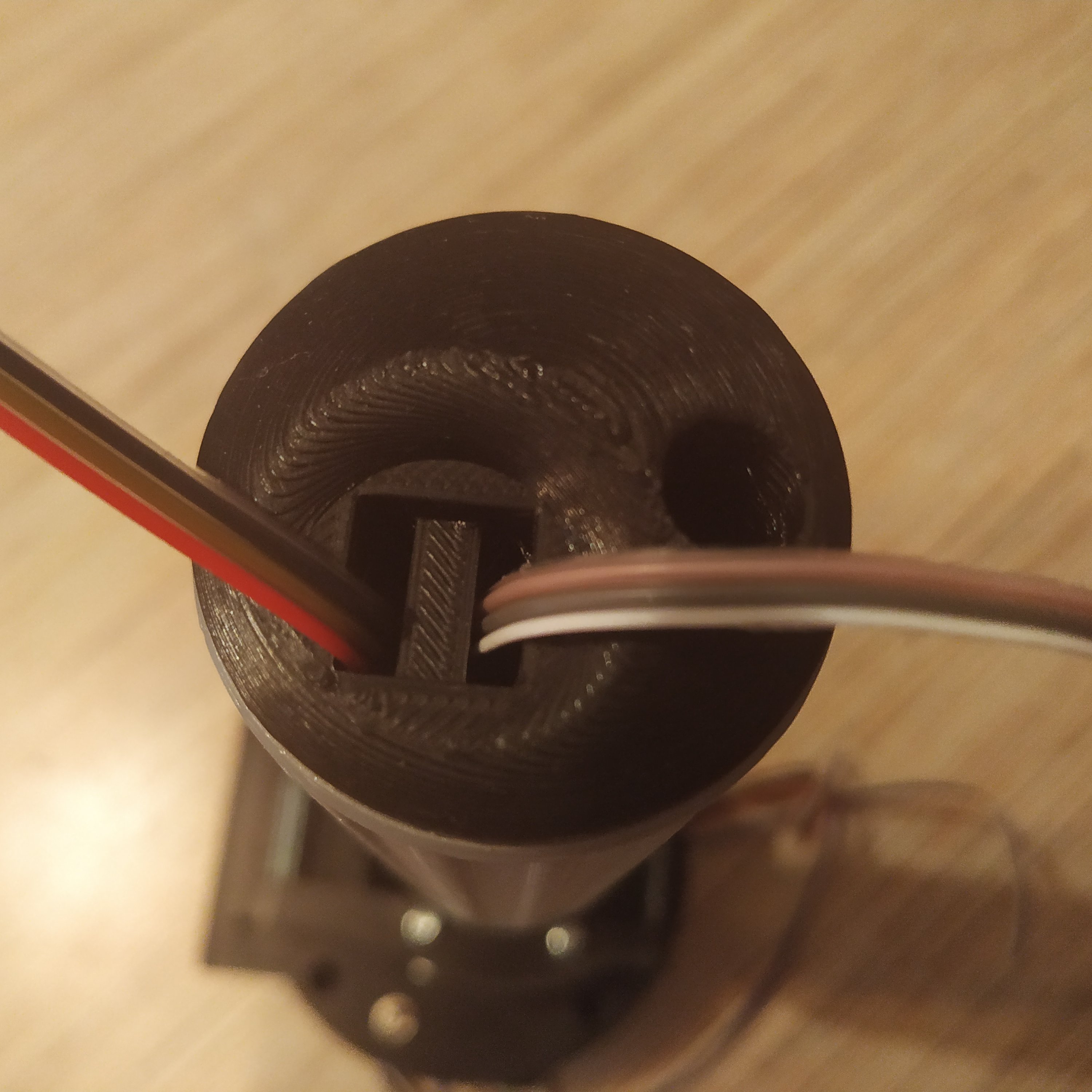
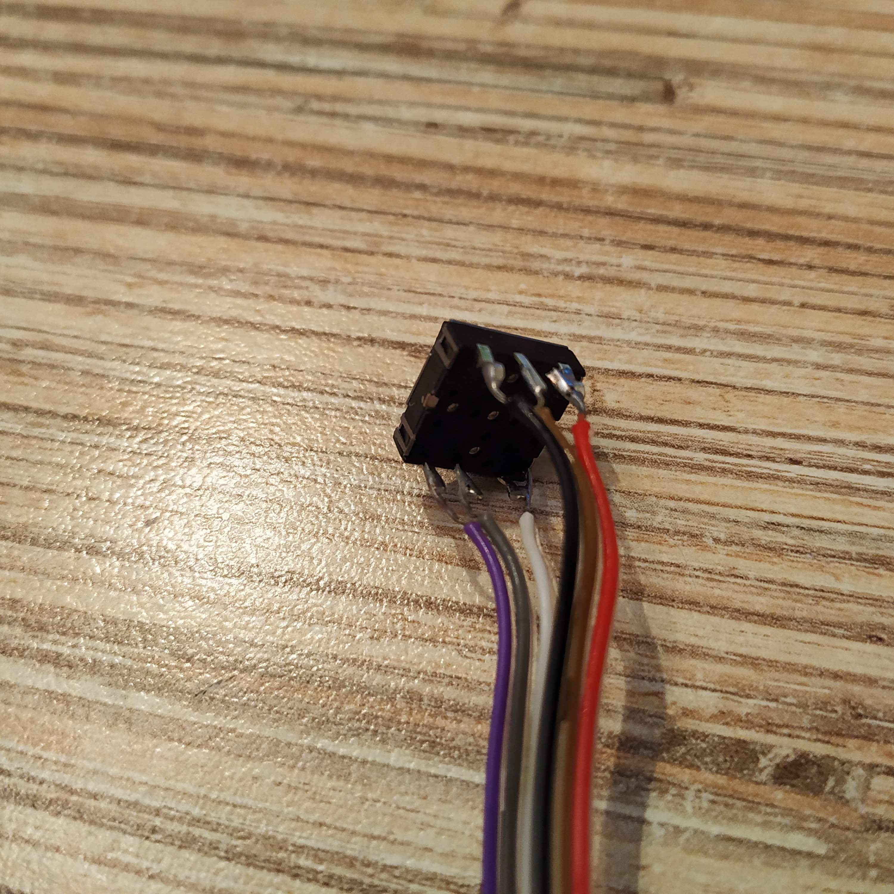
2. Install the simple collective throttle grip part and split the hat switch cable into two parts as shown in the picture below (mind the colors!). Route the cable through the cable guide in the throttle frame part 2, then insert two parts of the cable into slits of the hat switch slot strictly as shown below!
| AS SEEN FROM THE BACK (RIGHT PIC BELOW) | ||
| TOP LEFT | TOP MID | TOP RIGHT |
| BLACK | BROWN | RED |
| BOTTOM LEFT | BOTTOM MID | BOTTOM RIGHT |
| PURPLE | GRAY | WHITE |
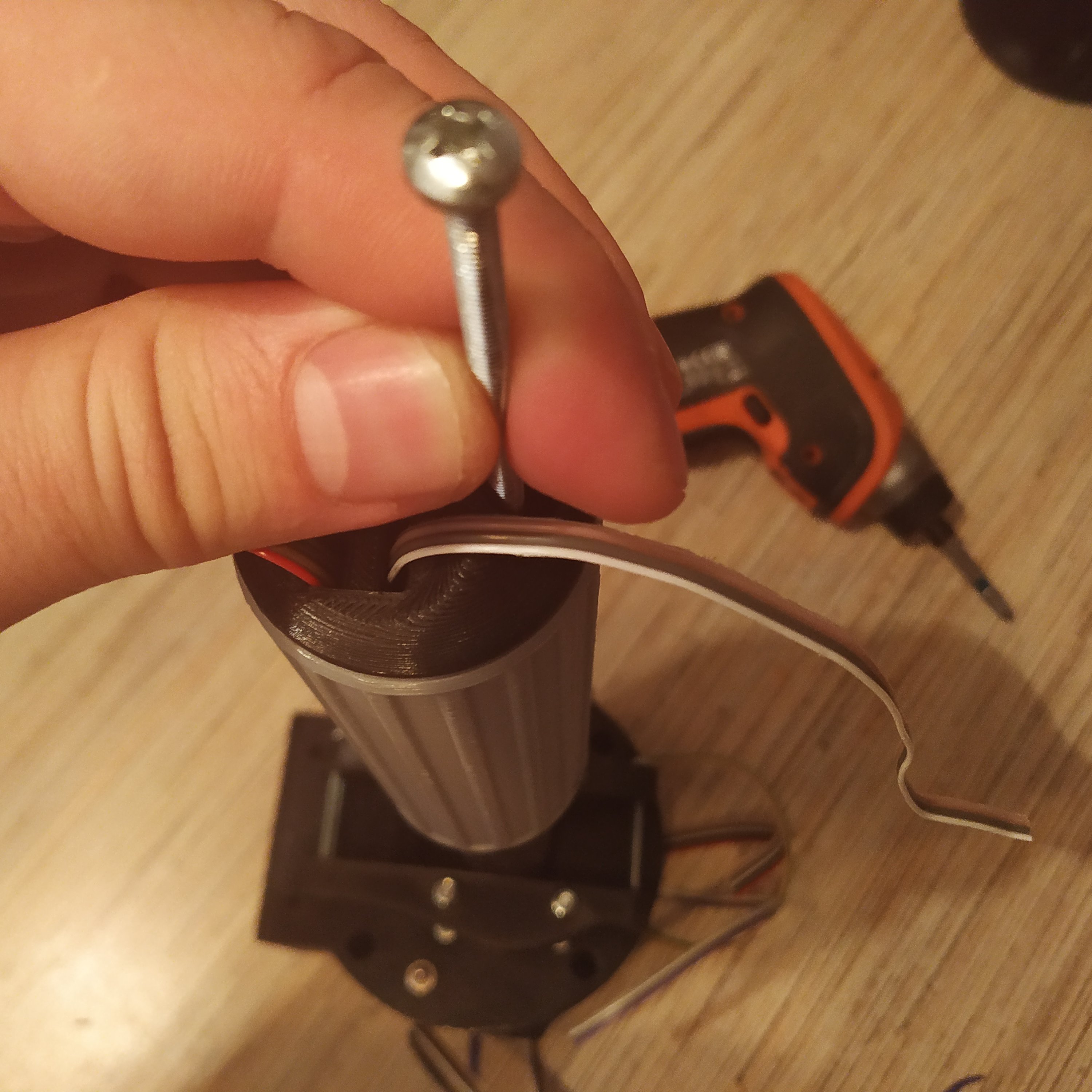
3. Install the throttle frame part2, pulling the hat switch cable carefully so it won't be caught in between the parts. Insert an M4x70mm screw and tighten it.
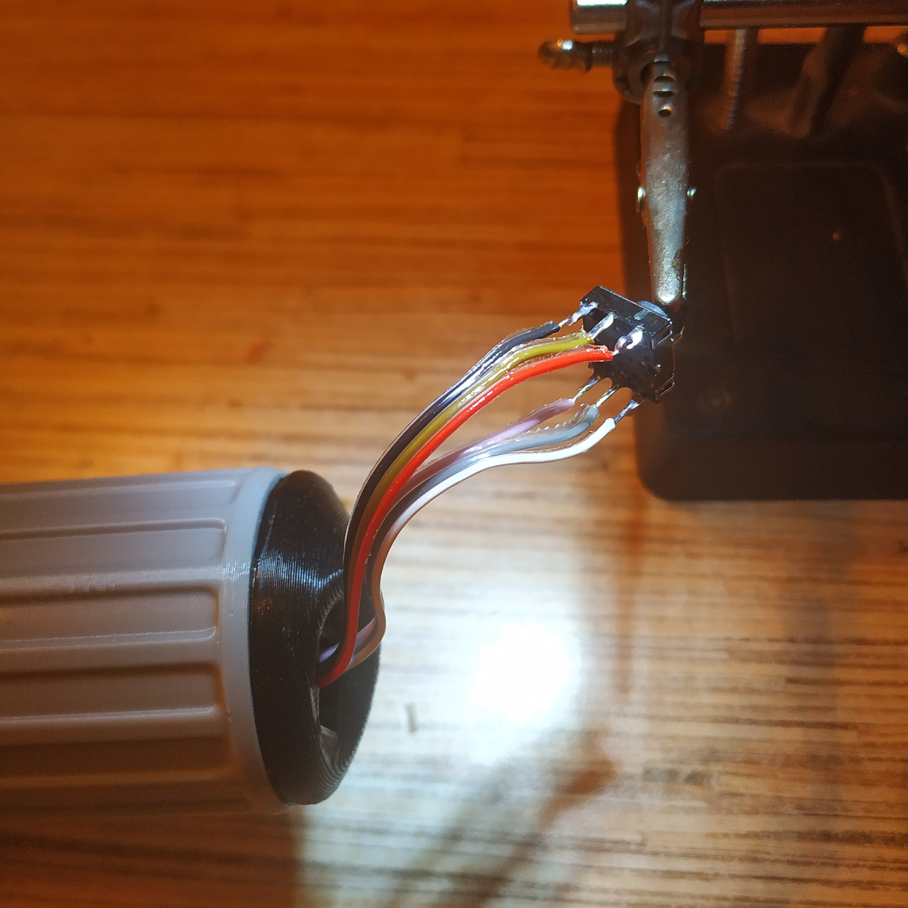
4. Cut an excess length of the cable and solder wires to the hat switch as shown in the pictures below. Note that the ground pin is slightly closer to the center one than the one on the right. When finished, carefully push the hat switch down into its socket.
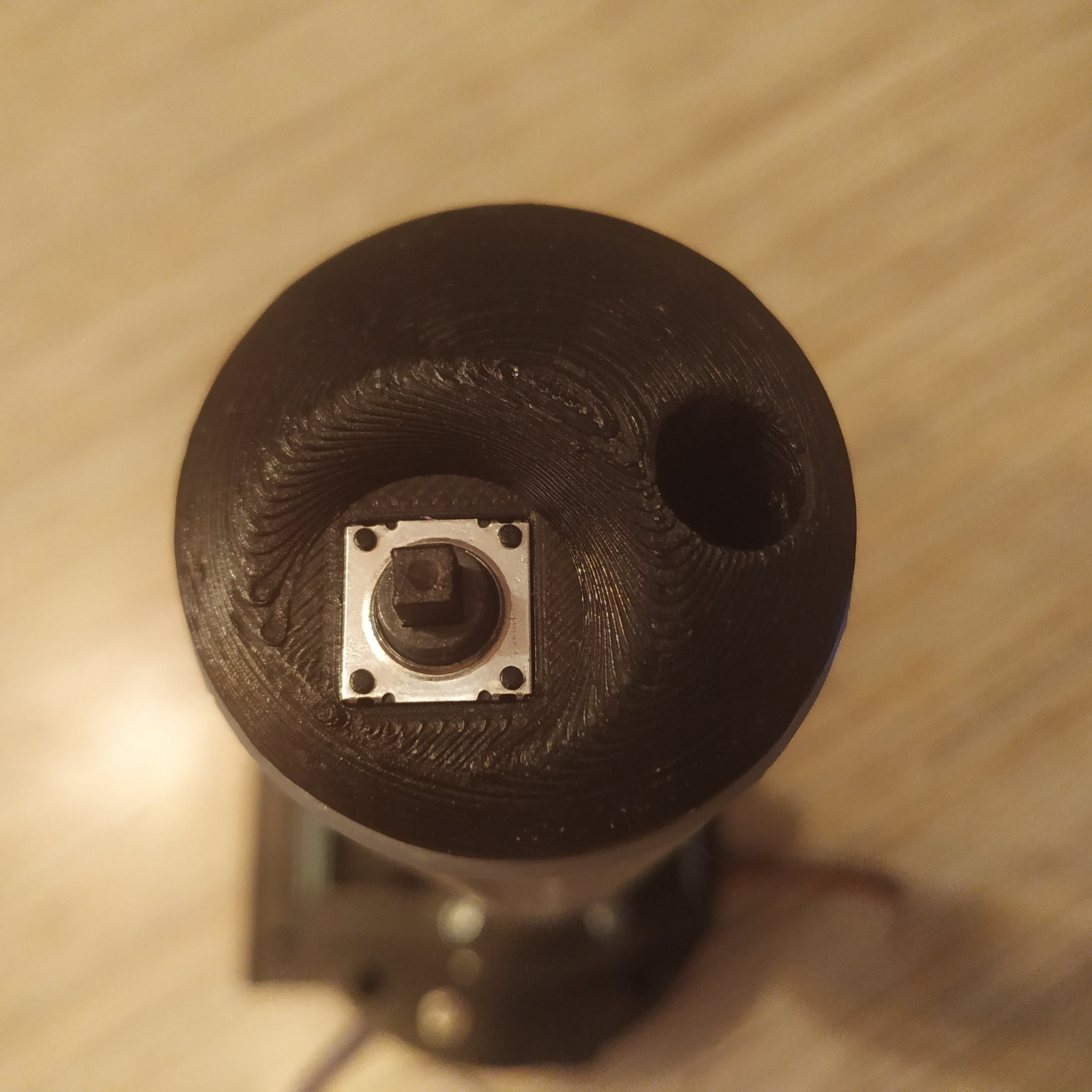
5. Test the hat switch cap fit on a spare hat switch. If it's overly tight, print it with a lower infill and number of perimeters and vice versa, or put it on and off to a spare hat switch a few times until it widens a bit. When you feel that it's safe to put it on, put it on the soldered hat switch.
If you ever happen to break the hat switch, it can be replaced in a couple of minutes! This lever is perfect maintenance-wise as everything can be pulled apart really quickly.
6. Solder the other side of the hat switch cable as shown in the table below (don't forget to remove the led on pin 13):
| CONN POINT A | CONN POINT B |
|---|---|
| HATSW GND | COLL BASE GND CABLE JOINT |
| HATSW BROWN | ARDUINO PIN 8 |
| HATSW RED | ARDUINO PIN 9 |
| HATSW PURPLE | ARDUINO PIN 10 |
| HATSW GRAY | ARDUINO PIN 11 |
| HATSW WHITE | ARDUINO PIN 12 |
7. ENCLOSURE WITH EXTENSION SLOT ONLY If you've chosen to make a lever with the base extension slot, solder the 4-wire i2c cable as shown in the picture below. You can solder it directly to your base extension of choice, or add an RJ-45 plug so you can connect stuff easily later.
| CONN POINT A | CONN POINT B |
|---|---|
| I2C VCC | VCC CABLE JOINT |
| I2C GND | VCC CABLE JOINT |
| I2C SCL | PRO MICRO PIN 3 |
| I2C SDA | PRO MICRO PIN 2 |
8. Flash the lever with firmware for your chosen variant (I2C or USB) and calibrate it. (Please consult with this video on YouTube if you're not familiar with the process). The video is for the single collective, but for this one, the process is the same minus the name of the lever.
That's it! Enjoy flying ![]()
