Table of Contents
Pneumatic actuator mod for collective levers


Summary
This mod makes collective levers perfect. Please consider to give it a whirl! This mod is compatible with all MKIII, and MKIV levers. For levers with integrated heads, the mod should be used without a counterweight.
You will need:
- 1 * MAL16-100 pneumatic actuator
- 1 * 20×10x1000mm aluminum rectangular pipe
- 4 * M3x50mm screws and nuts
- 2 * M4x80mm screws
- 4 * M8x55 bolts
- 2 * M8x45 bolts
- a pack of M8 washers, spring washers, and nuts
- 4 * M8x100 bolts
- 2* M5*12 screws
- 1 * M6x30 bolt
- 2* M6 nuts
- 4 x 608 bearings (standard skateboard bearings)
Repository path
simchair4_models\printable components\peripherals\helicopter\collective lever\d_pneumatics
Assembling guide
1. Cut a 310mm piece off a 10x20mm rectangular aluminum tube. Make a chamfer with a file on both ends of the tube.
2. Press-fit the 310mm piece of the 10x20mm aluminum tube into its socket in the lower lever connector ring part. Drill 4mm holes in it and fix the tube to the part with 2 M4x80mm screws. Use reinforced M4 washers on both sides and nyloc nuts. Press-fit 4 M3 nuts into their sockets.


3. Insert 2 M3x50mm strengthening screws into their sockets, use M3 reinforced washers on both sides of screws and nyloc nuts.


4. Insert an M4x80mm strengthening screw from the outer side of the part. Use a nyloc nut to fix it in it's place.


5. Put a cap onto the uncovered end of an aluminum tubing.

6. Press-fit 2 M8x40mm bolts into their sockets in the counterweight housing back. Fix with nuts.


7. Put the counterweight housing back onto the tube. There is no need to tighten the nuts too much, at this point.


8. Put a detent ring onto the cylinder, as shown in the picture below:

9. Put an M6 nut into its socket in upper cylinder connector hinge.

10. Screw the upper hinge onto the cylinder rod. Hold the rod as shown in the picture below, while doing it.


 11. Put 2 M5 screws into their sockets in the cylinder, turn for a couple of turns. Do not tighten the screws!

12. Put the lower hinge connector onto the cylinder, and fix it in place with an M6x30 mm bolt. Apply thread locker to the nut.

13. Put 2 M8x55mm bolts into the lower hinge part. Fix it with nuts.


14. Take an M8x45mm bolt. Put a bearing and a nut onto it. Add a washer.


15. Put the bolt through the lower hinge, and screw it to the lower cylinder connector part, as shown in following pictures:


16. Put 5 washers onto the bolt.

17. Add a bearing and a nut. Tighten. Ensure jitter-free operation of the hinge.

18. Prepare the second M8x45 bolt as described in step 14. We will be connecting the upper hinge with it.
19. Screw the bolt into the lever connector's lower ring part, to something like 70% of its length.

20. Put 5 washers onto the bolt.
 21. Put a bearing and a nut onto the bolt and screw it completely. Tighten. Check jitter-free operation of the hinge.
 22. Put the back of the lower hinge onto it.

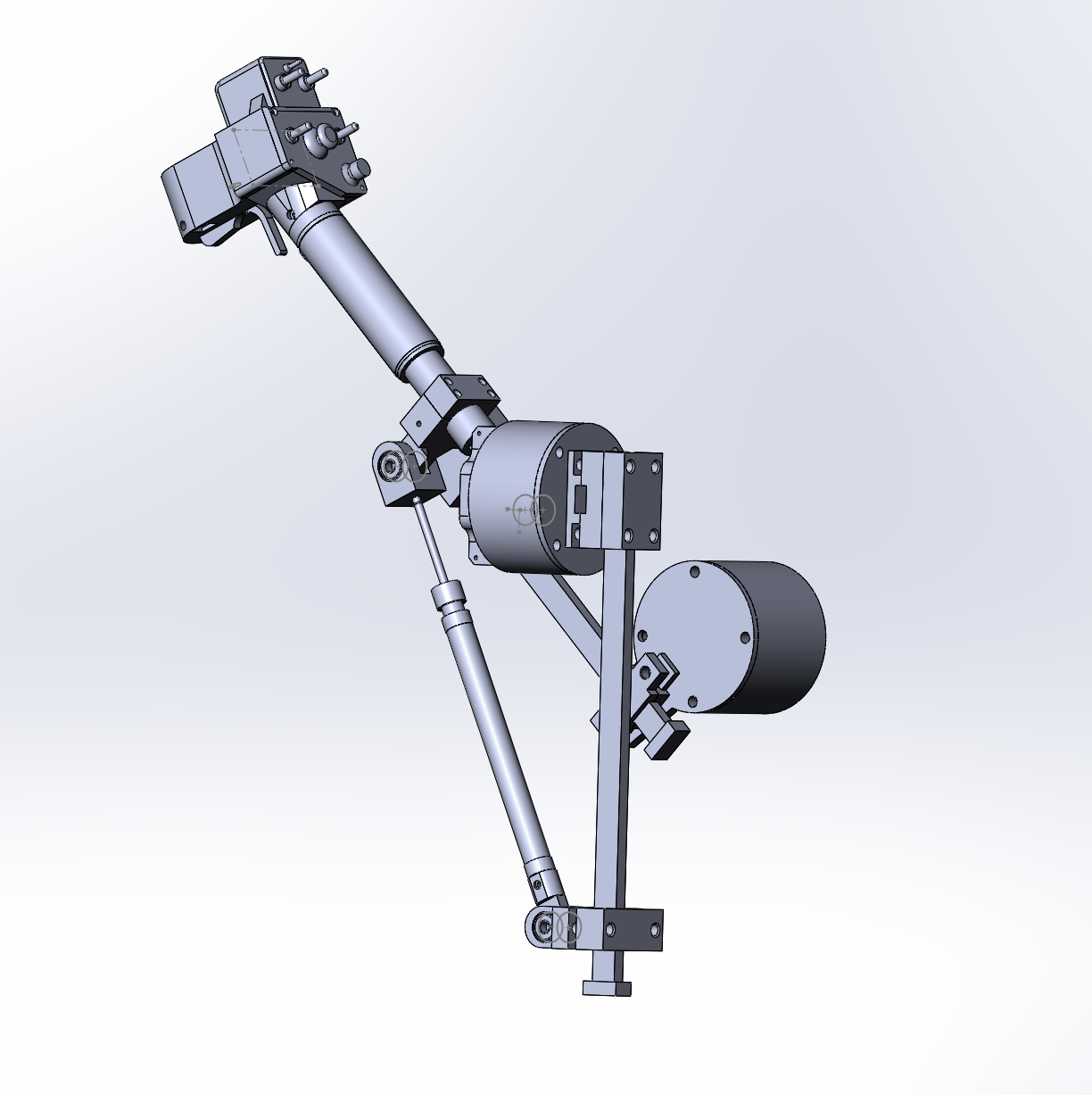
That’s it, here’s how it should look at this point:
23. Cut a 340mm piece of 10x20mm aluminum tubing, file the ends, and attach a cap onto it.

No we are ready for the mod installation!
Installation
1. If you are installing the mod on an older collective, you have to change the rear lid of the housing. To do that, cut an Ethernet plug off, unscrew 4 bolts that hold the lid, and carefully detach electronics from the lid if it is glued with hot glue or two-sided tape. Install the new lid. The result should look like that:

2. We will be mounting our collective to the piece of 10x20mm aluminum tubing, inserted into a frame, designed for use with an IKEA GUNDE chair.

3. Press-fit the 340mm piece of alu tubing into its socket in pneumatic_mod_enclosure_bottom_p2_pneumatic_mod02 part.


4. Put the lever onto the frame and fix with enclosure_bottom_p2 part
 5. Add enclosure_bottom_p3 part, put 4 washers, 4 spring washers onto the bolts, then tighten everything with nuts.


6. Put the lever connector ring onto the lever and fix lightly with screws so it won’t fall. Estimate where the lower hinge will go and put it onto its frame. Turn lever connector as necessary so the hinge will fit onto its frame.


7. Try pulling the lever and make sure it moves through all its range. Adjust lever connector position if necessary.

8. Tighten 4 screws of the lever connector carefully. Do not overtighten!

9. Put the back part of the lower hinge on. Use washers and nuts to fix it.

10. Adjust lever detent ring nut until the lever will be resting on the detent in a full-down position. Use thread locker or a drop of hot glue to fix the nut (it should be removable).

11. Adjust the counterweight mount so it won’t protrude too much.

12. Screw 4 M8x100mm bolts halfway into the counterweight housing.

13. Put some weight into the counterweight housing (start with 500g or so for a twin collective, 400g for the single one) and check if it’s enough to hold the lever in all of its travel range.


14. After you have checked that the lever stays where you leave it, screw bolts completely into the box and put nuts on.

15. Adjust friction tensioner so it will protect the lever from unwanted lateral movements, but won't cause any unwanted friction.

16. The last step is to adjust the airscrews of the cylinder, screw them in, for more resistance, unscrew them a bit for less. You will want a silky-smooth movement of the lever. Make sure the Screws do not touch the rod! If they do, they will damage the cylinder!

Congratulations! With this mod, you will get the most out of your collective. Final adjustments can only be made while flying, so take your favorite helicopter for a test ride! You want a perfect, silky-smooth operation of the lever, with reliable fixation in all of it's travel range. Please note, that depending on airscrews position you may need to hold the lever for one or two seconds before taking your hand off.
