Table of Contents
MKIV MASTER CONTROLLER V2A
Summary
The MKIV master controller V2 is a successor of the first version. It features 5 ports for your peripherals, one of which can be used for flashing their firmware (in version V2A), and a durable USB-B socket. A separate flashing cable is no longer needed. This version of the controller is compatible with all peripherals including MKIII ones, except for VRMax collective head, which was replaced with the VRMax pedestal that does its job much better.

Components
- 1 x Arduino Leonardo
- 1 x MTS-102 switch
- 1 x PBS-10-B2 button
- 1 x USB-B socket USBB-1J (DS1099-W)
- 5 x TJ8P8C Ethernet sockets (12,5x15x17,6mm)
- 4 x M3x30mm screw
- 2 x M3x35mm screw
- 4 x M3x6mm screw
- 4 x M3 nuts
- 2 x M3 nuts with cap
- A ribbon cable
Downloads
Assembly guide
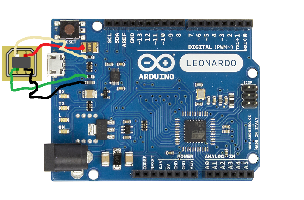
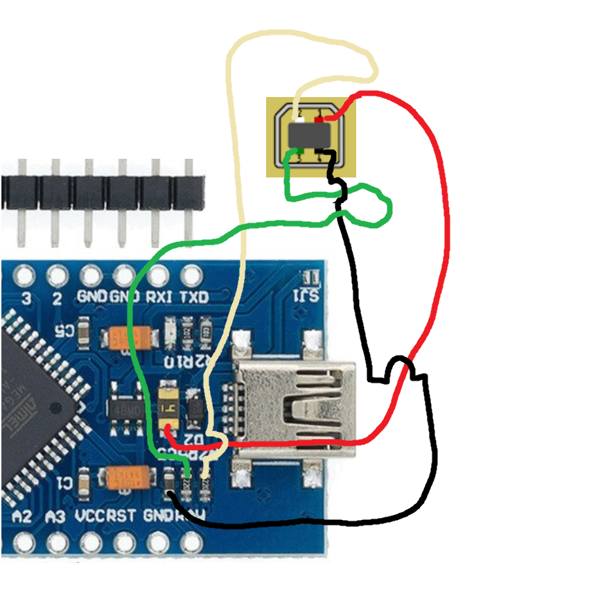
1. Insert the Leonardo board into its place in the box, fix with 4 3x6mm screws. Snap off the Micro-USB socket, remove the power input socket and solder the USB-B one as shown in the picture below (you can use the Pro Micro board alternatively, but do not do it yet if you don't understand what you will need to change - no docs yet):

WARNING! We will be using cable joints to connect wires of the I2C cable. Make sure only 1 wire from
each joint goes from the tie to the board header or to each of the sockets. Do not attempt to solder
multiple wires to a single pin of the header or a socket!
2. Insert pin headers into the Leonardo board as needed and solder wires to them as described below:
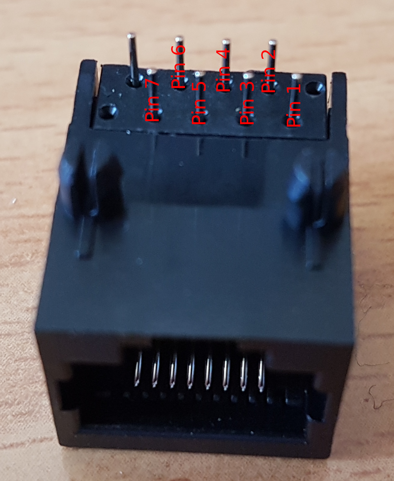
WARNING! Let's agree to call the separated socket used for flashing peripherals "Socket 1".

VCC -> VCC cable joint -> SOCKETS 1-5 PIN1
GND -> GND cable joint -> MTS-102 -> PBS-10-B2 -> SOCKETS 1-5 PIN2
SCL -> SCL cable joint -> SOCKETS 1-5 PIN3
SDA -> SDA cable joint -> SOCKETS 1-5 PIN4
TX -> SOCKET 1 PIN 5
RX -> SOCKET 1 PIN 6
PIN4 -> SOCKET 1 PIN 7
PIN2 -> MTS-102
RST -> PBS-10-B2
Time to test the controller in both modes. Look at the “How to use the controller” section below and make sure each port works as an I2C port and also check the flashing function of socket 1. Secure everything with hot glue, put the lid on, insert 4 M3x30mm screws. That's it!


How to use the controller
This controller can work in two modes:
- F (FLY) - the main mode used for operation and flashing of the master controller.
- P (PROGRAM) - the mode, used for flashing peripherals.
To flash the master controller firmware:
1. Check that the mode switch is in the "F" position and connect the master to your PC
2. Install libraries from z_libraries folder (copy them to Arduino/libraries folder of your IDE)
3. Open the master firmware and select your hardware on the device definitions tab
4. Select the COM port with "Arduino Leonardo" next to it in IDE
5. Select "Arduino Leonardo" board from the board menu
6. Press "Upload" button
7. That's it! After "Upload finished" message proceed to configuration of your peripherals.
To use the controller for flashing of your peripheral:
1. Connect the peripheral to the separated port of the controller
2. Set the mode switch to "P"
3. Press the R (RST) button
4. Open the firmware file for your peripheral
5. Select the COM port with "Arduino Leonardo" next to it in IDE
6. Select "Arduino Pro Mini" from the board menu
7. Press "Upload" button
8. After IDE says "Upload finished", flip the switch back to "F"
9. The controller will reboot and pop up as a joystick in joy.cpl

WARNING! to upload the master controller firmware, use "F" mode and choose "Arduino Leonardo"
from the board menu!
