simchair4:guide_master_controller_v2
This is an old revision of the document!
Table of Contents
MKIV MASTER CONTROLLER
Summary
The MKIV master controller V2 is a successor of the first version. It features 5 ports for your peripherals, one of which can be used for flashing (in version V2A). A separate flashing cable is no longer needed. This version of the controller is compatible with all peripherals including MKIII ones, except for VRMax collective head, which was replaced with the VRMax pedestal which does its job much better.
Components
- 1 x Arduino Leonardo
- 1 x MTS-102 switch
- 1 x PBS-10-B2 button
- 5 x TJ8P8C Ethernet sockets (12,5x15x17,6mm)
- 4 x M3x30mm screw
- 2 x M3x35mm screw
- 4 x M3x6mm screw
- 4 x M3 nuts
- 2 x M3 nuts with cap
- A ribbon cable
Downloads
Assembly guide
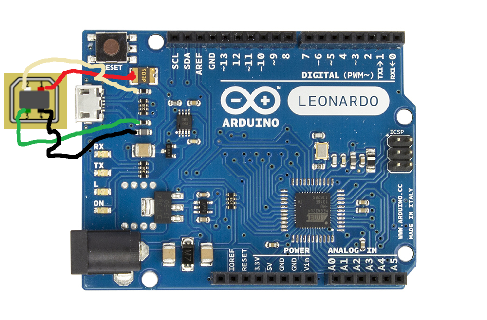
1. Insert the Leonardo board into its place in the box, fix with 4 3x6mm screws. Snap off the Micro-USB socket and solder the USB-B one as shown in the picture below:
WARNING! We will be using cable joints to connect wires of the I2C cable. Make sure only 1 wire from
each joint goes from the tie to the board header or to each of the sockets. Do not attempt to solder
multiple wires to a single pin of the header or a socket!
2. Insert pin headers into the Leonardo board as needed and solder wires to them as described below:
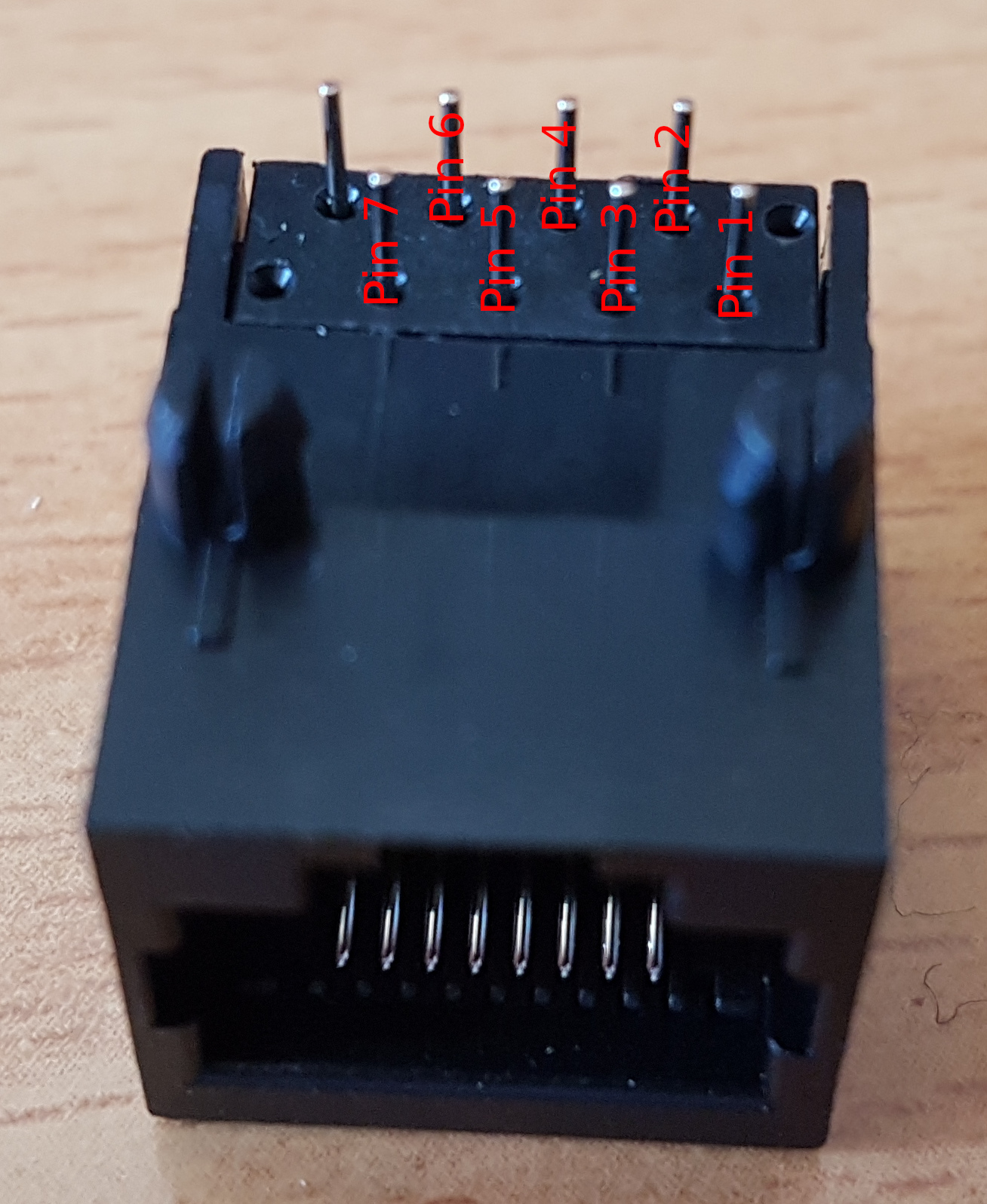
WARNING! Let's agree to call the separated socket used for flashing peripherals "Socket 1".

VCC -> VCC cable joint -> SOCKETS 1-5 PIN1
GND -> GND cable joint -> MTS-102 -> PBS-10-B2 -> SOCKETS 1-5 PIN2
SCL -> SCL cable joint -> SOCKETS 1-5 PIN3
SDA -> SDA cable joint -> SOCKETS 1-5 PIN4
TX -> SOCKET 1 PIN 5
RX -> SOCKET 1 PIN 6
PIN4 -> SOCKET 1 PIN 7
PIN2 -> MTS-102
RST -> PBS-10-B2
simchair4/guide_master_controller_v2.1606423518.txt.gz · Last modified: 2020/11/26 21:45 by hc625ma
Except where otherwise noted, content on this wiki is licensed under the following license: GNU Free Documentation License 1.3
