Table of Contents
Bell 412 Style Collective Head
About Collective Heads
A collective head is a device that is mounted onto the top of the collective lever to extend its functionality. A few of them are currently available under the MKIV line of hardware.
The recommended default option for flying in VR is the Compact (integrated) collective head (MKVI).
There is a simpler version available, the Simple (integrated) collective head as well as replica ones:
- Bell412-style collective head (MKVI) (You are currently here)
- Bell206-style collective head (planned)
Summary
This is the AB412-style collective lever head. It’s not 100% scale, but is close enough and has quite a lot of stuff in it: two Arduino Pro Minis onboard, two hat switches, seven 3-way switches and three buttons on the top panel, and optionally up to two rotary pots on its sides, along with a mode switch. It also has some interesting software-driven features:
- four switch modes to cover all your needs
- you can choose which switches to use: toggle 3-way switches of spring-loaded ones in any combination
- DCS UH-1 idle stop compatibility mode – this thing can realistically start and stop the Huey, although it doesn’t support advancing throttle past idle-stop detent with a joystick axis
- X-Plane X-Trident AB412 idle stop compatibility mode (with an external Lua script)
- mode switch triples your buttons and spring-loaded switches number
Special Features
- XTrident AB412 startup /shutdown support
- DCS Huey startup / shutdown support
- Collective hold (right thumbstick click)
- hat switches support 4-way or 8-way modes
- 4 switch operation modes for every possible use scenario
- mode switch triples the number of switches / buttons configured as pushbuttons
Available mods
enclosure bottom variants (check the Mods downloads): 
- scale version
- two side pots and a mode switch
- two side pots, no mode switch
- one pot, no mode switch
Components
You will need:
- 2 x Arduino pro mini board
- 2 x KY-023 joystick module
- 1 x USBtoCOM adapter (e.g., PL2303) or another Arduino to program it
- 1 x PBS-10B-2 button
- 1 x KN3(B)-103A-A3 switch (starter, in a real 412 it seems to be a toggle type switch)
- 2 to 7 x MTS-223-A2 (ON)-OFF-(ON) spring-loaded switches
- 0 to 5 MTS-223-A1 ON-OFF-ON toggle type switches
- some wires
- 2 x m3x20 screws and nuts
- 2 x m3x40 screws and nuts
- 1 x Simchair MKIII I2C controller (Arduino Leonardo based) (https://www.thingiverse.com/thing:2919692)
- 1 x Simchair MKIII collective (single or twin-throttle version)
- 1x TJ8-8P8 ethernet socket
Downloads
Assembly guide
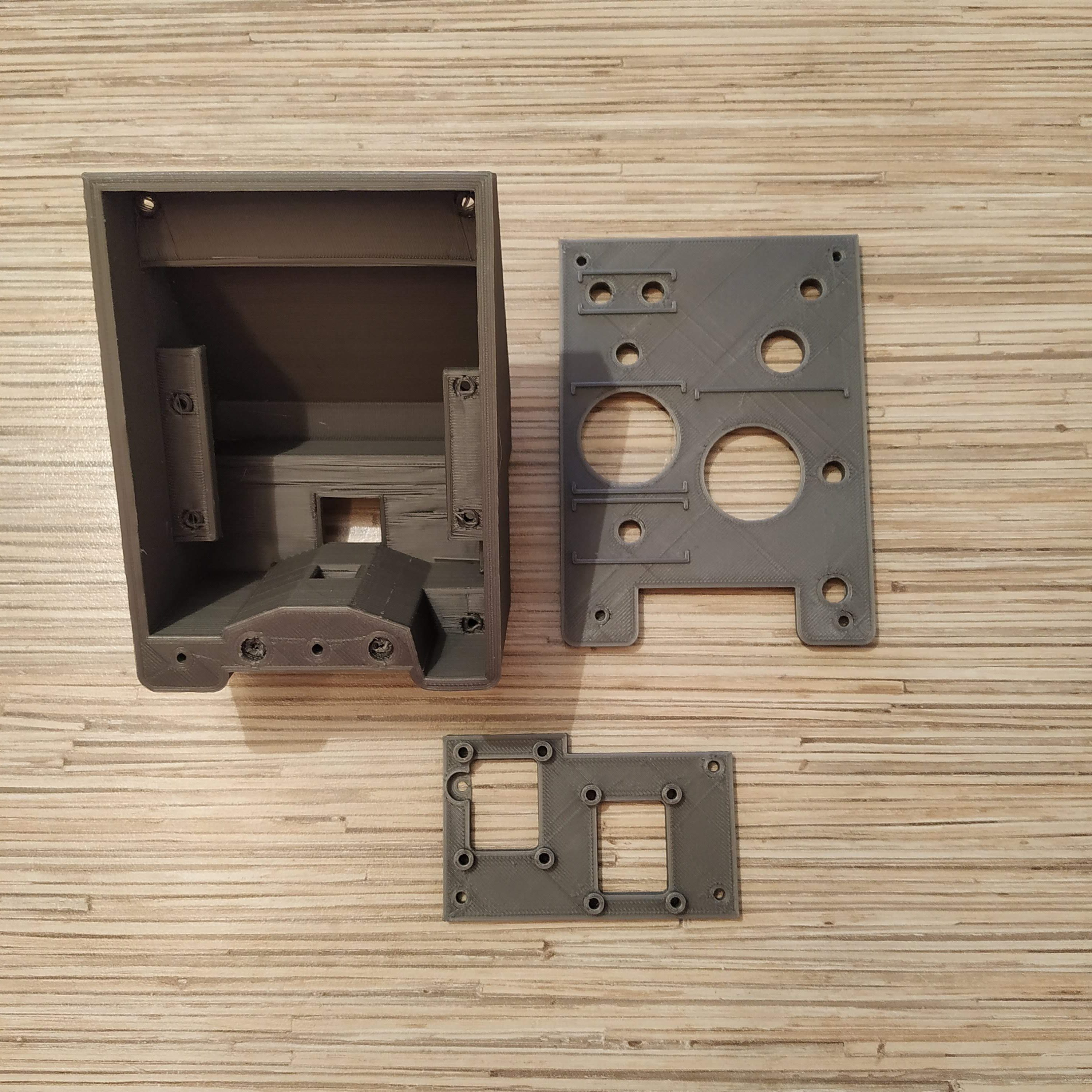
1. Remove supports from all printed parts. Take a spare piece of square alu pipe and put the head housing onto it several times to ensure a tight, but not overly tight, fit. Press-fit nuts into their sockets.
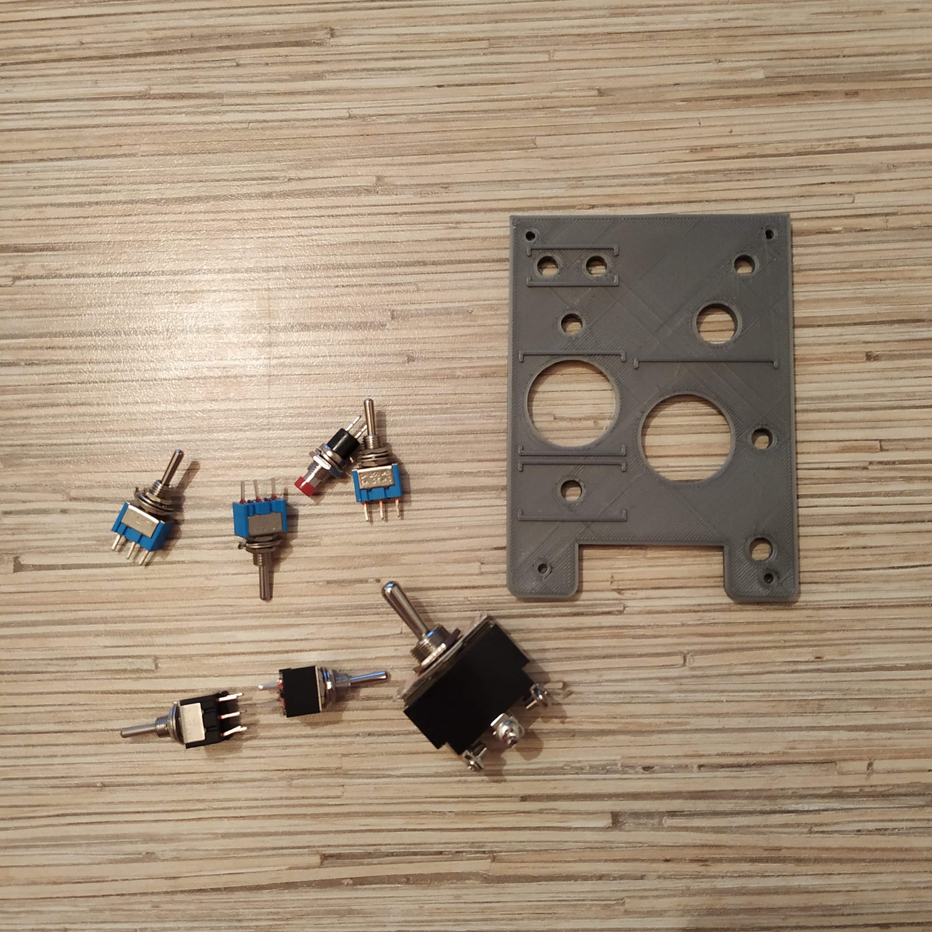
2. Insert switches and a button into the top cover. By default, there are two (ON)-OFF-(ON) momentary switches, that go to two lower slots on the left side of the head cover. All others are toggle type – ON-OFF-ON. Switch next to the starter (idle stop) flips sideways.
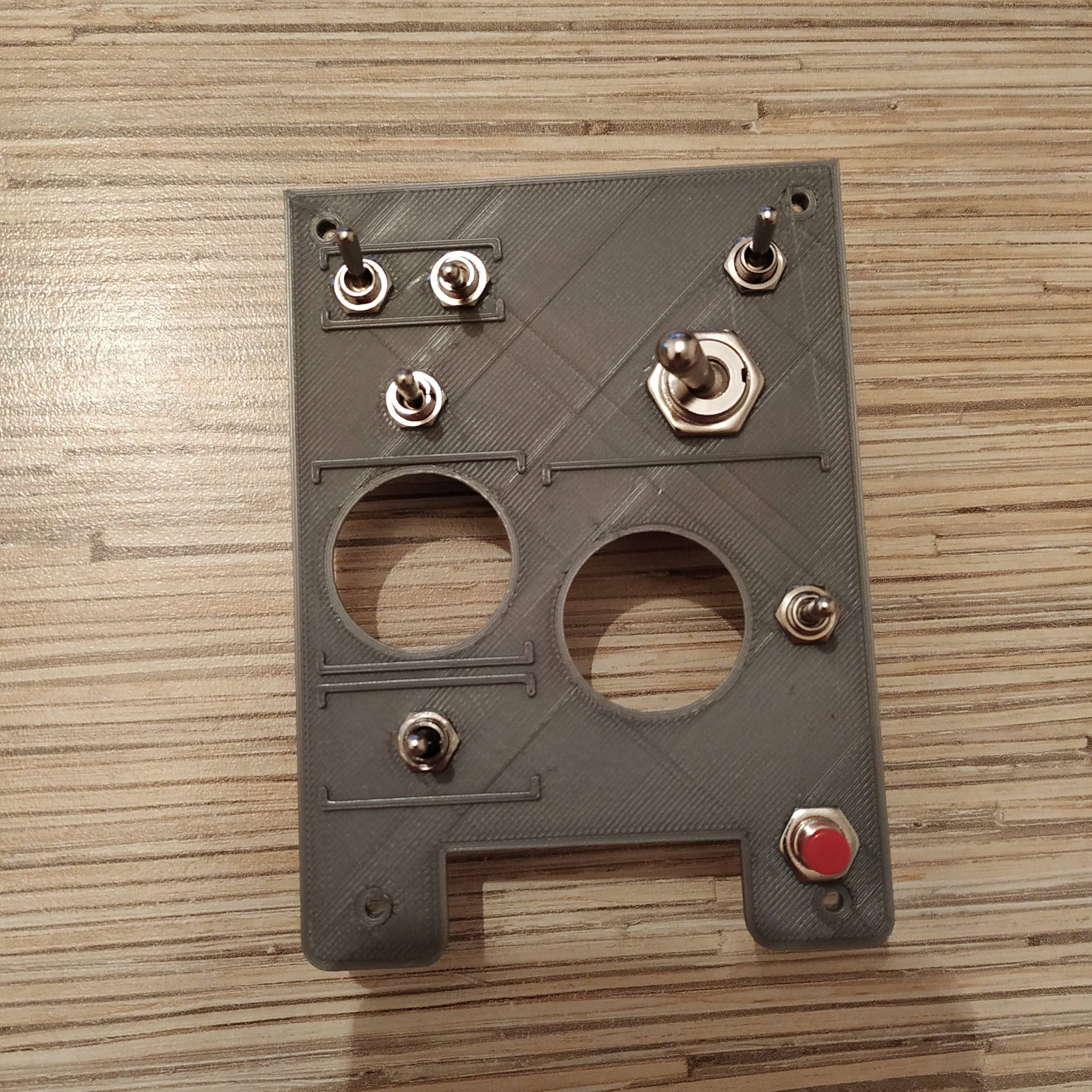
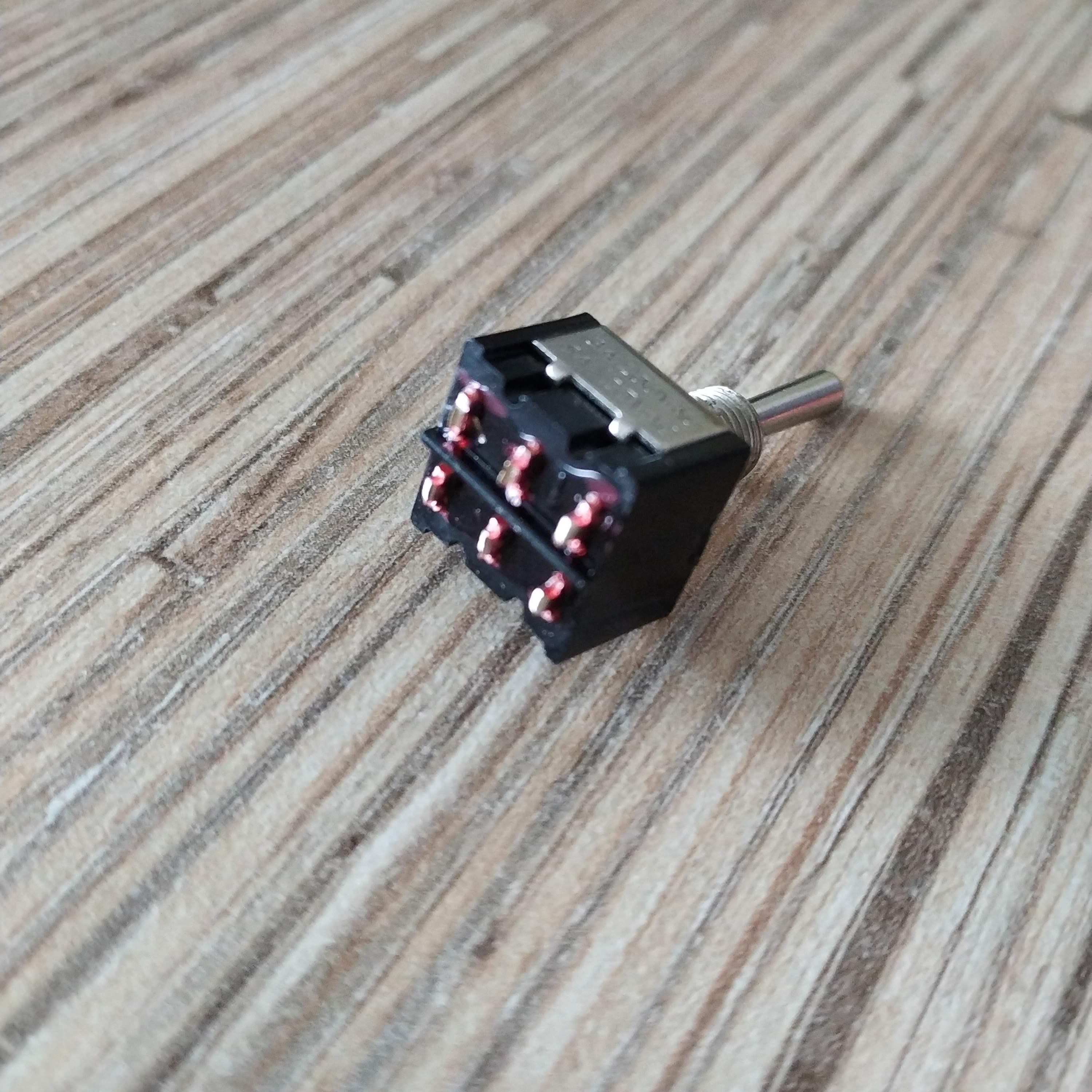
3. IMPORTANT FIX: cut legs of the bottom left switch (when viewed from the top (previous picture), face side, the spring-loaded governor switch) short! Otherwise, it will be shorting pins of the KY-083 board under it!
4. Break off parts of contact points with screws from a starter switch. Apply some solder to remaining parts of contact pads.
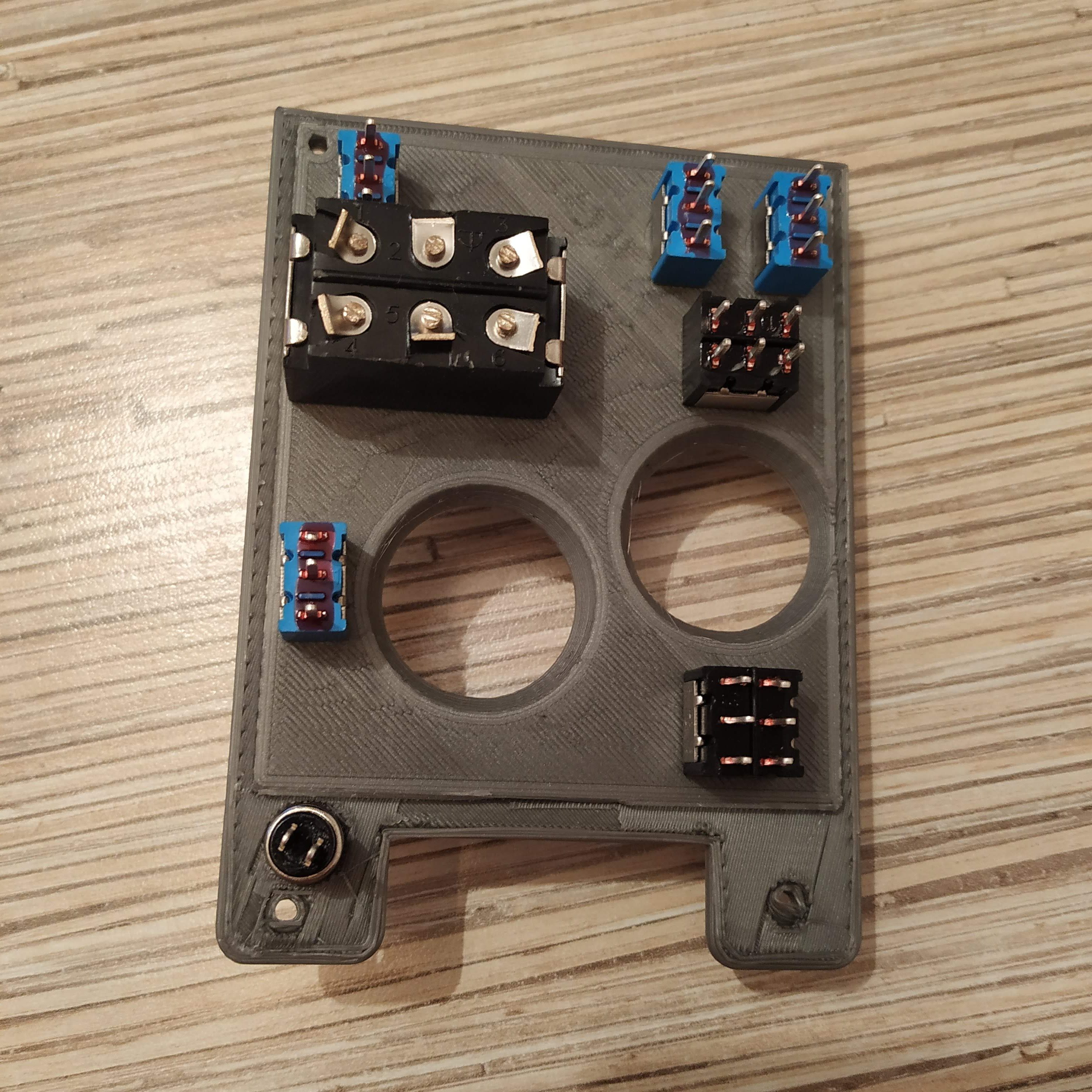
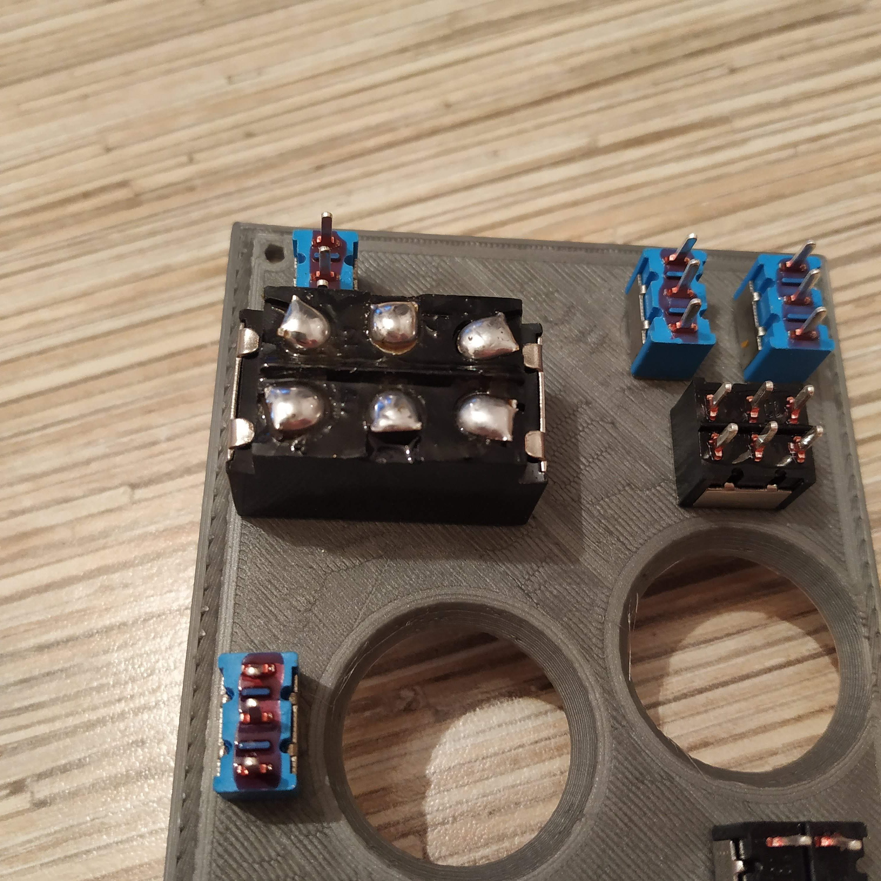
5. Now, it’s time to solder ground pins together. Cut 1 wire from the ribbon cable, make cuts in its isolation where needed, and solder it to middle pins of each switch and one of the button pins. Note that for switches with 2 rows of pins, you only need to use 1 row (they are not connected internally). Proper cable routing is very important at this stage.
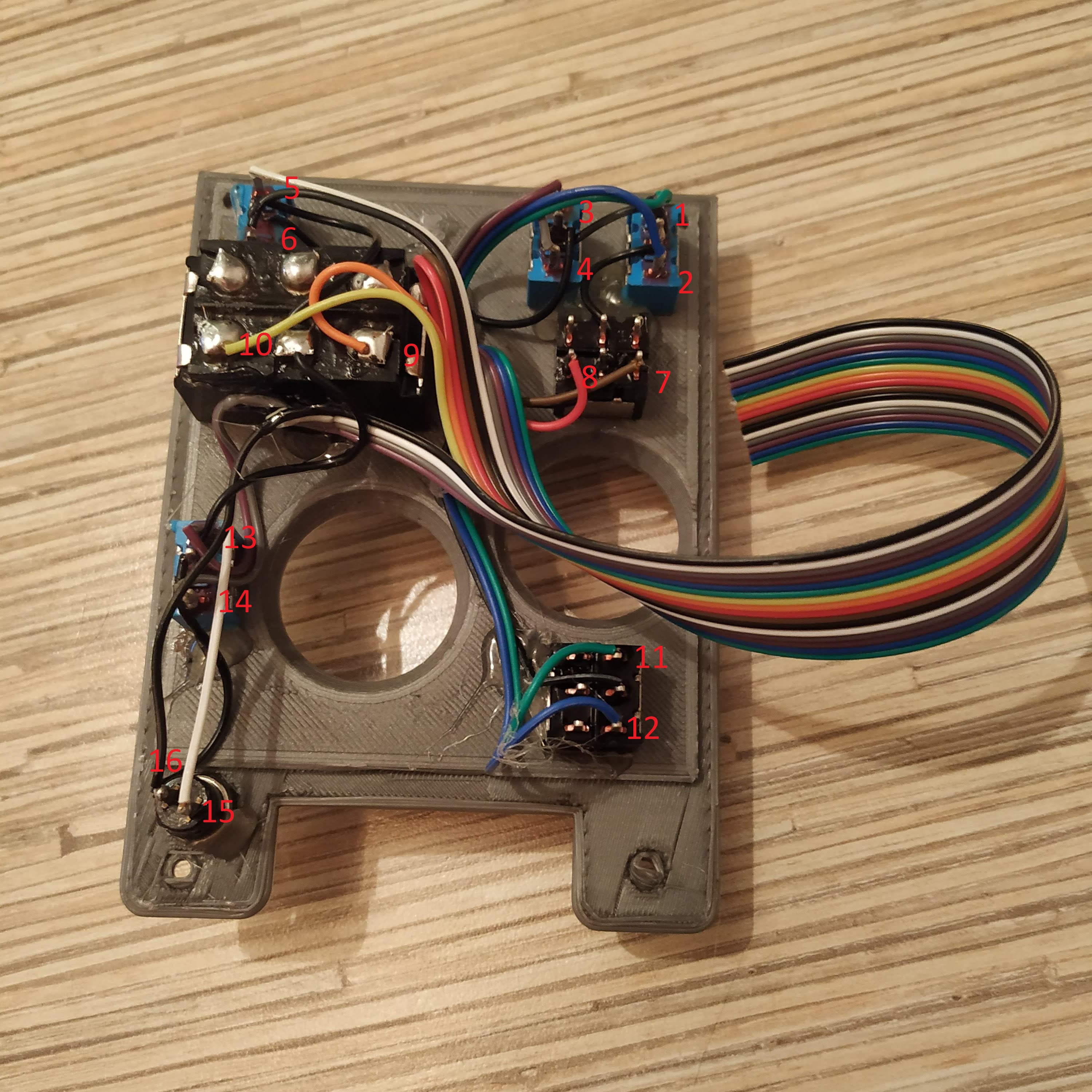
6. Cut a 16-wire cable off the ribbon cable. Position the head cover so the little red button will be on the bottom. Turn the cover and start soldering wires, 1st wire to the upper contact point of the 1st switch from the right, 2nd wire to its lower contact point, 3rd wire to the upper contact point of the next switch to the left in the same row, and so on until everything will be connected. Switches flipping sideways should be soldered starting from their rightmost contact point. The last wire goes to ground. When finished, secure everything in place with hot glue. Please consult with the picture below.
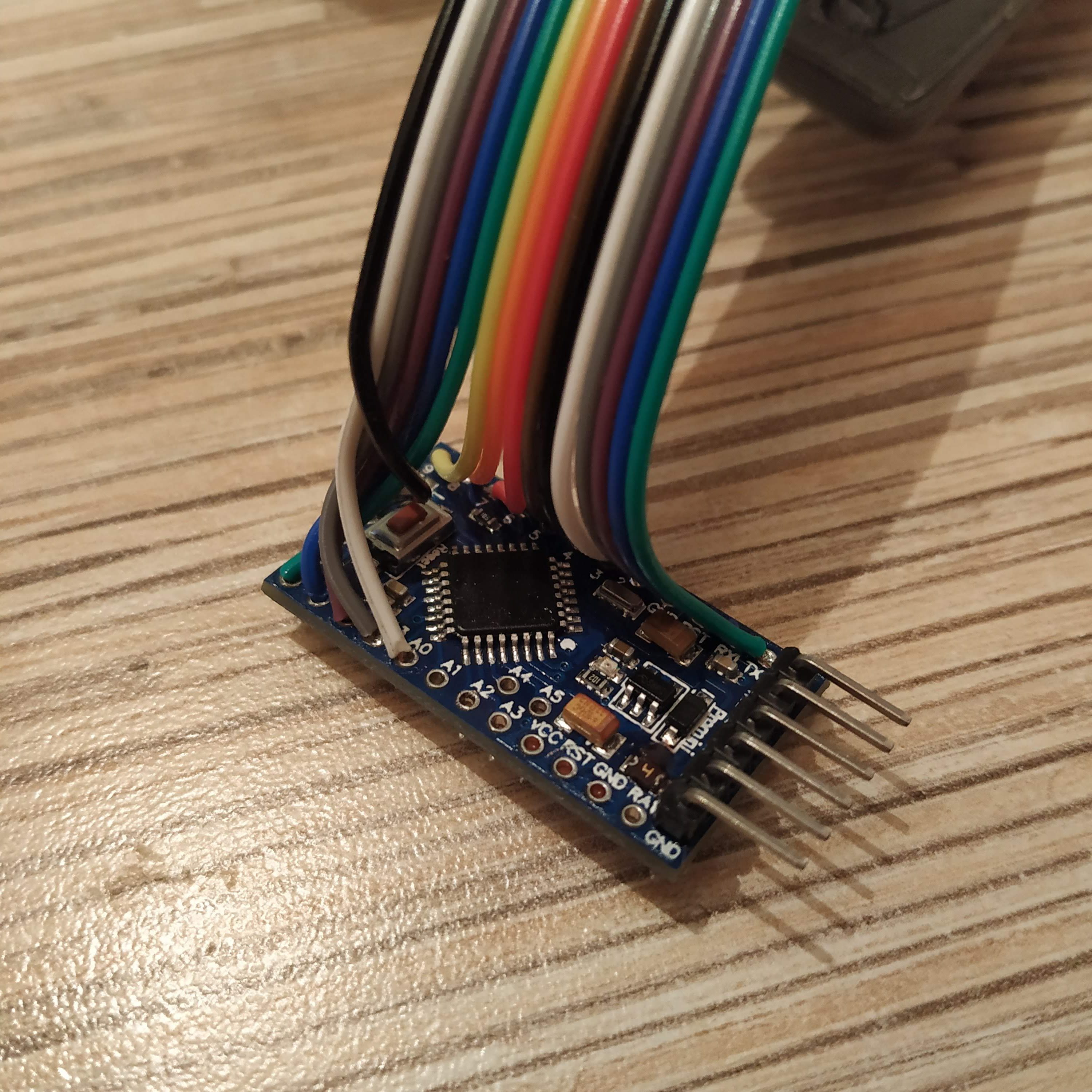
7. Now it’s time to solder another end of the 16-wire cable to an Arduino pro mini (solder a UART header to it first). Start from pin0,(top-right switch upper contact pad should go there) and solder all wires one by one. Remove the led, connected to pin 13 (you can find it next to pin 9). The 11th wire goes to pin 10. The 15th wire will go into A0 pin, that’s ok. The 16th wire goes to a GND pin.
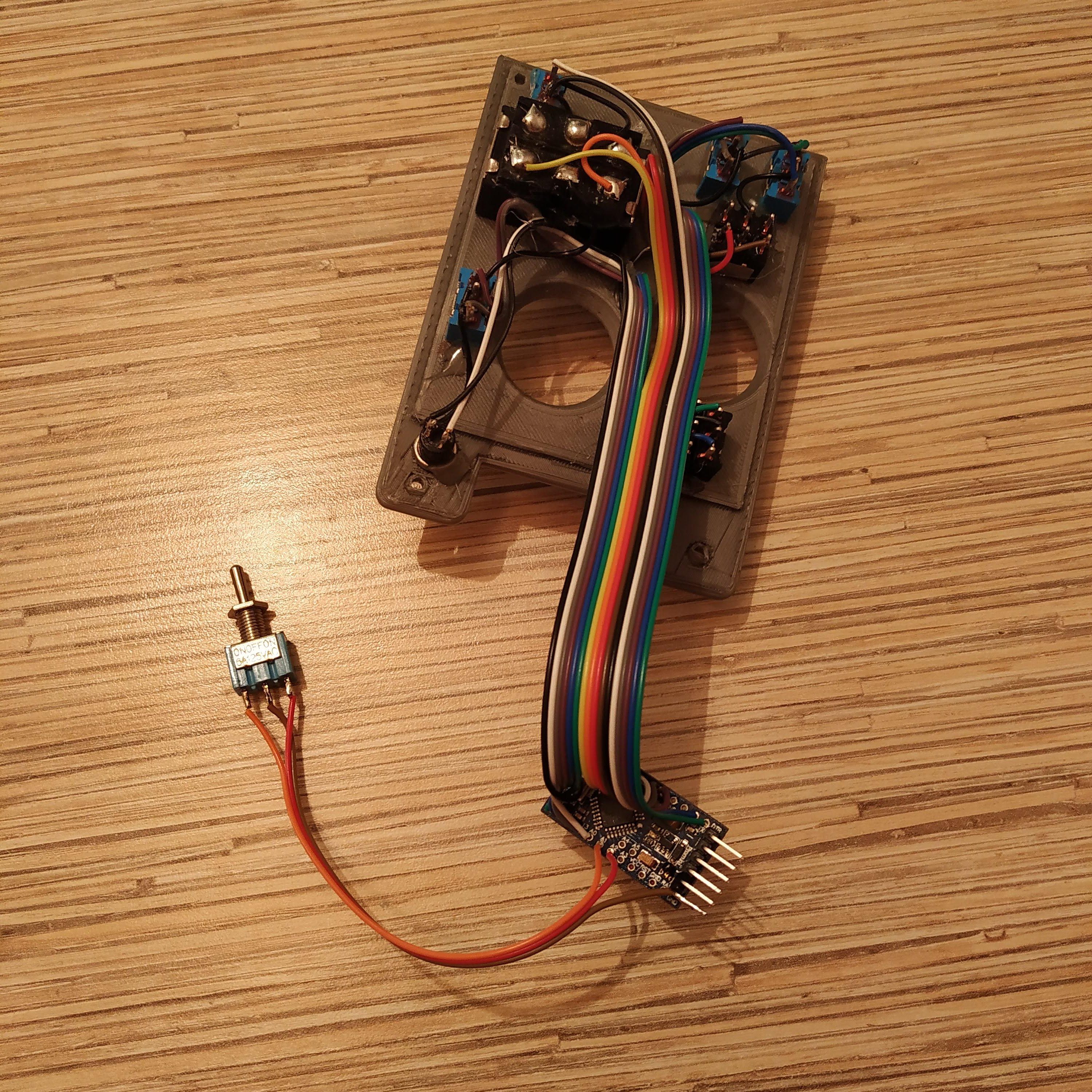
8. Cut a 3-wire cable from a ribbon and solder it to the mode switch. Connect its signal wires to pins A1 and A2. Solder the pot’s ground to the outermost GND pin on UART header. The switch controller is now assembled!
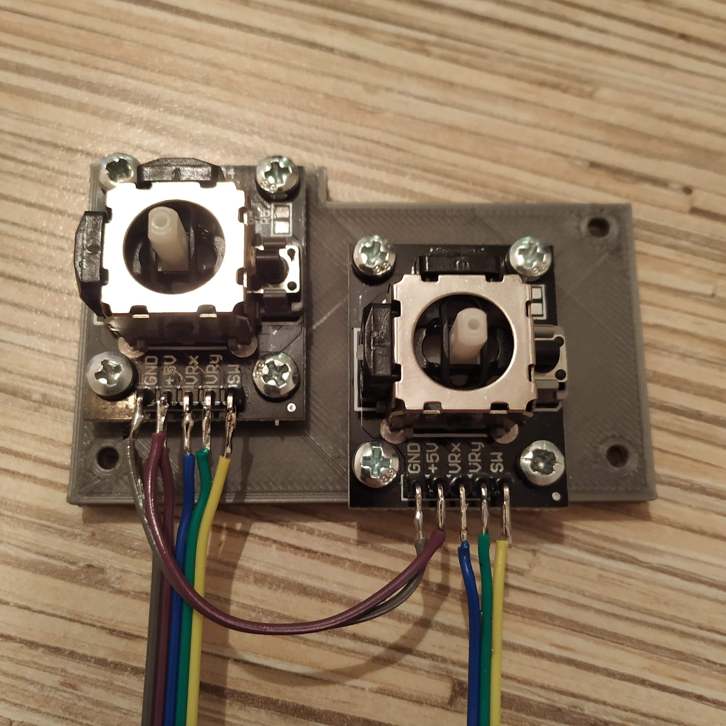
9. Let’s move on to the pot controller. Attach pot boards to their frame, pins facing backward, with 8 M3x6mm screws. (or you can use 2 M3x6mm screws on the left side and 10mm screws elsewhere) .
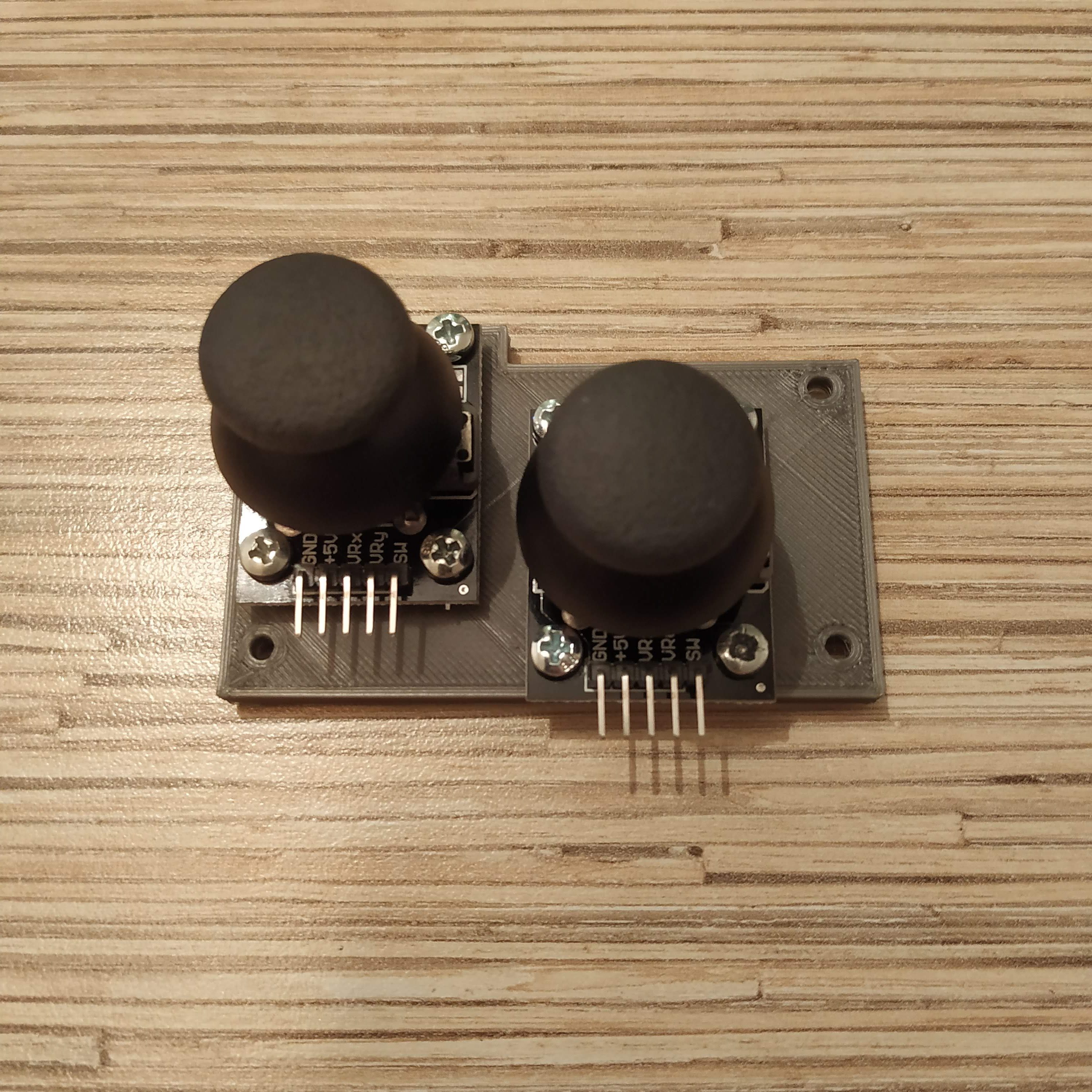
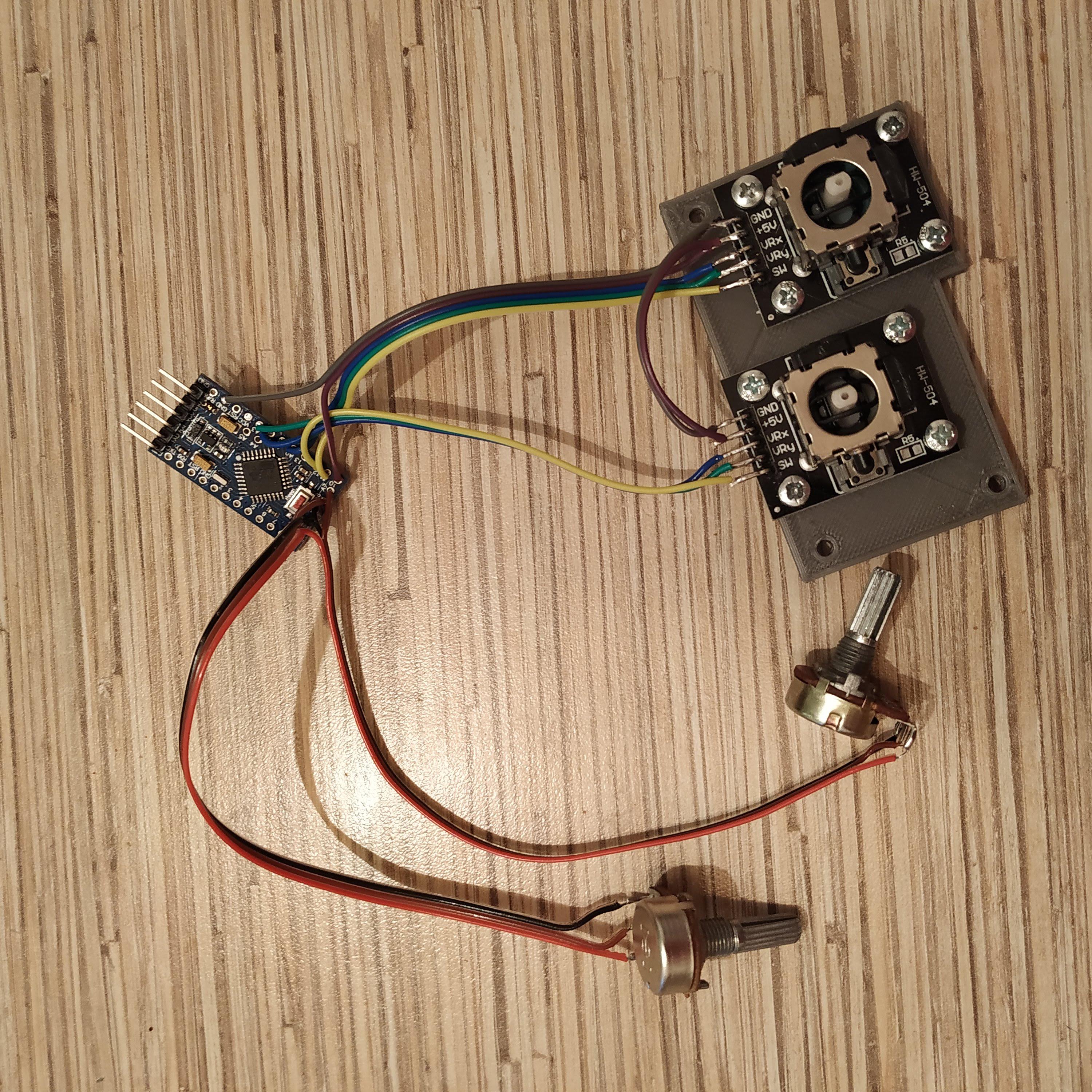
10. Solder wires to pot boards and connect them as follows:
- POT BOARD 1 VCC → POT BOARD 2 VCC → PIN 10
- POT BOARD 1 GND → POT BOARD 2 GND → GND
- POT BOARD 1 VRx → A0
- POT BOARD 1 VRy → A1
- POT BOARD 2 VRx → A2
- POT BOARD 2 VRy → A3
- POT BOARD 1 SW → PIN 11
- POT BOARD 2 SW → PIN 12
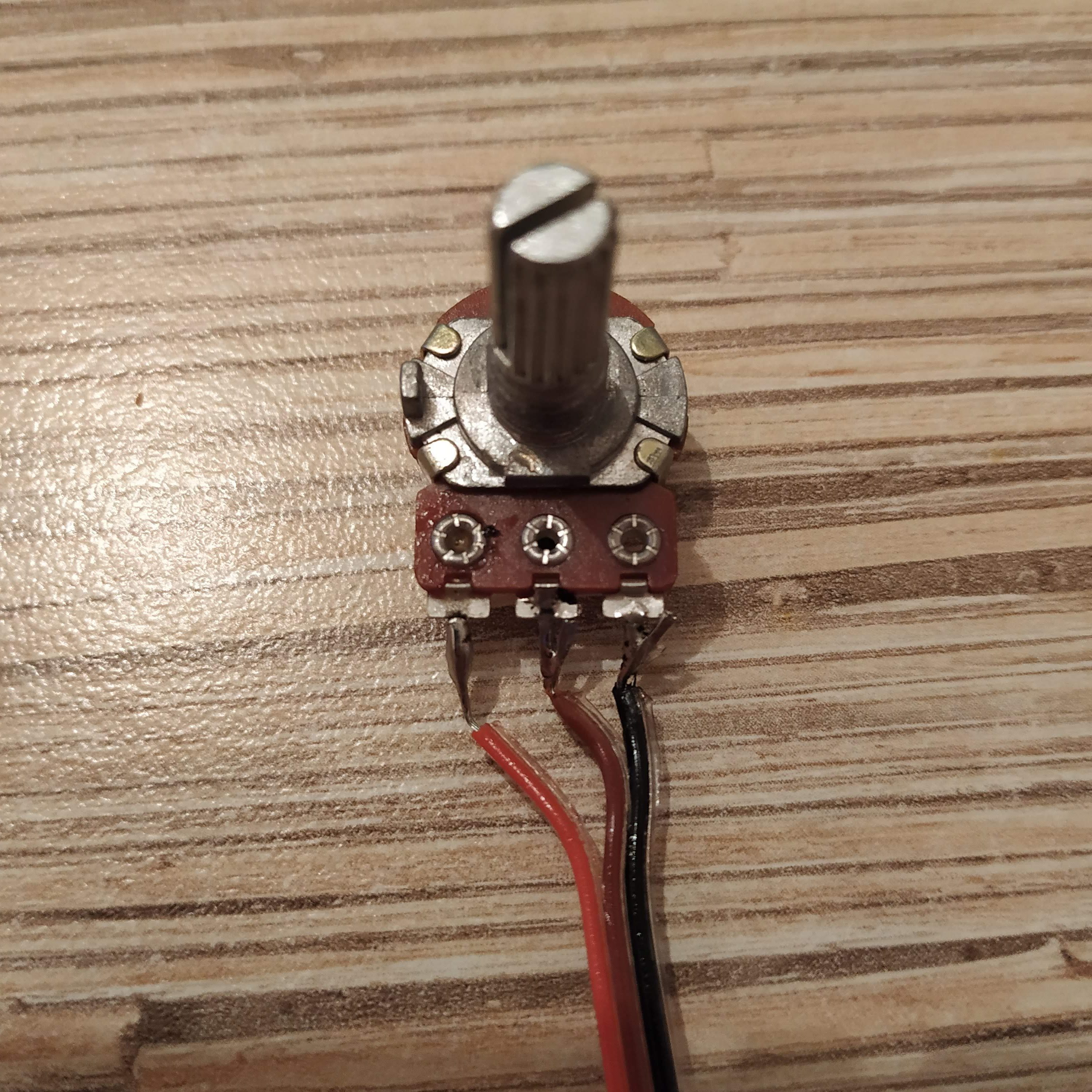
- ROTARY POT 1 VCC → ROTARY POT 2 VCC → PIN9
- ROTARY POT 1 GND → ROTARY POT 2 GND → GND
- ROTARY POT 1 SIGNAL → A6 (5V on the left leg of the pot facing up)
- ROTARY POT 2 SIGNAL → A7
The pot board is now assembled!
11. It’s time to connect everything with the I2C bus. Solder 4wires to 1st 4 pins of an ethernet socket, then connect them to both boards as follows:
- SWITCH CONTROLLER VCC → POT CONTROLLER VCC → Tj8-8P8 PIN 1
- SWITCH CONTROLLER GND → POT CONTROLLER GND → Tj8-8P8 PIN 2
- SWITCH CONTROLLER A4(SCL) → POT CONTROLLER A4 (SCL) → Tj8-8P8 PIN 3
- SWITCH CONTROLLER A4 (SDA) → POT CONTROLLER A4 (SDA) → Tj8-8P8 PIN 4
12. Electronics is finally assembled! Now, we need to flash Arduino boards and test everything. At first, connect a USB-UART adapter to boards and flash them with their corresponding firmware. You can uncomment Serial.prints to test switches (NOTE THAT ALL SWITCHES SHOULD BE CENTERED, YOU MAY NEED TO PRESS RESET MANUALLY DURING FLASHING PROCESS). When you press something, a “1” should turn on somewhere. After all, switches are tested, comment out “Serial.prints”, reflash the board, connect the ethernet socket to Simchair MKIII I2C controller and check that the collective head is recognized. Collective heads register as the 3rd “Arduino Leonardo” in the list.
13. Let’s put the stuff into the box. Start with inserting the ethernet socket. Secure it with a fair amount of hot glue. Put rotary pot 1 to the right side of the lever (relative to its normal position in a helicopter), rotary pot 2 to the left side, mode switch facing upwards with wire, connected to A1 pin.
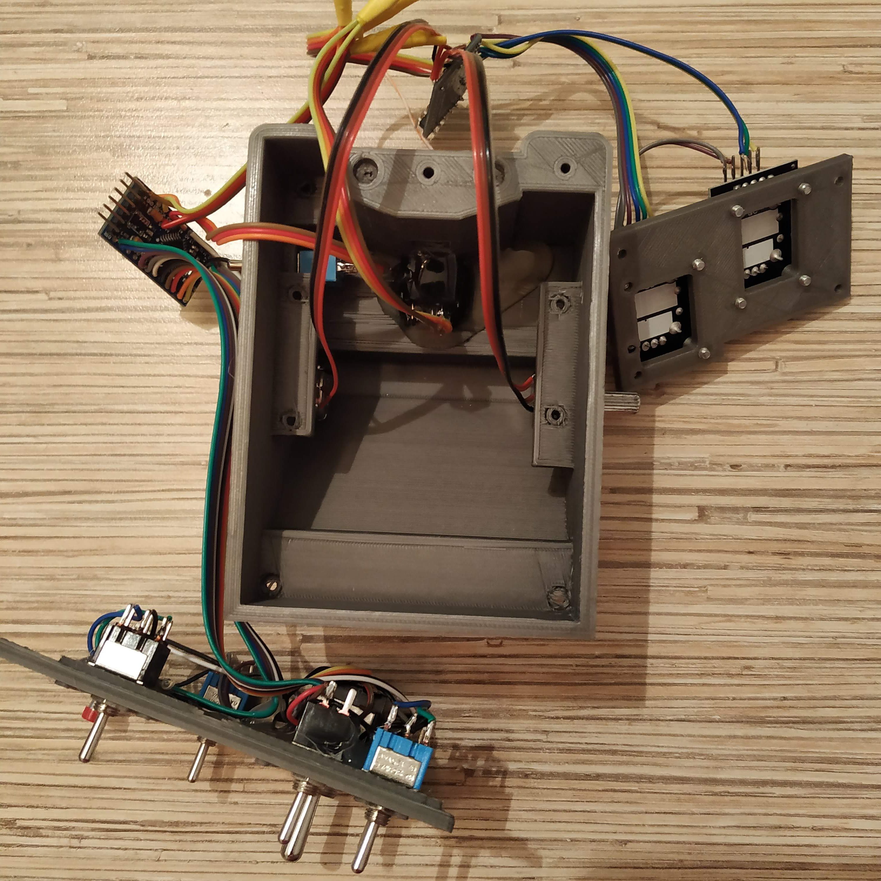
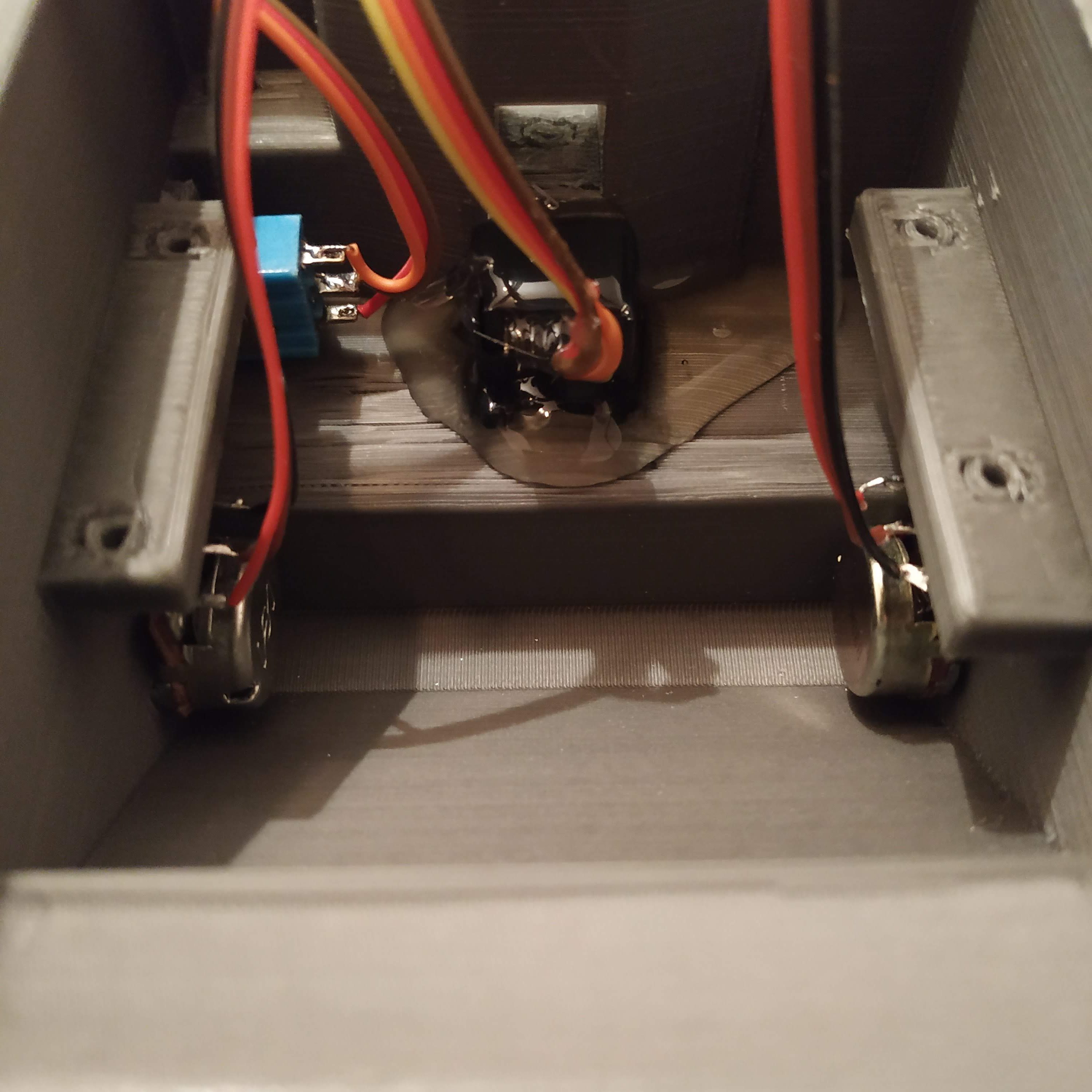
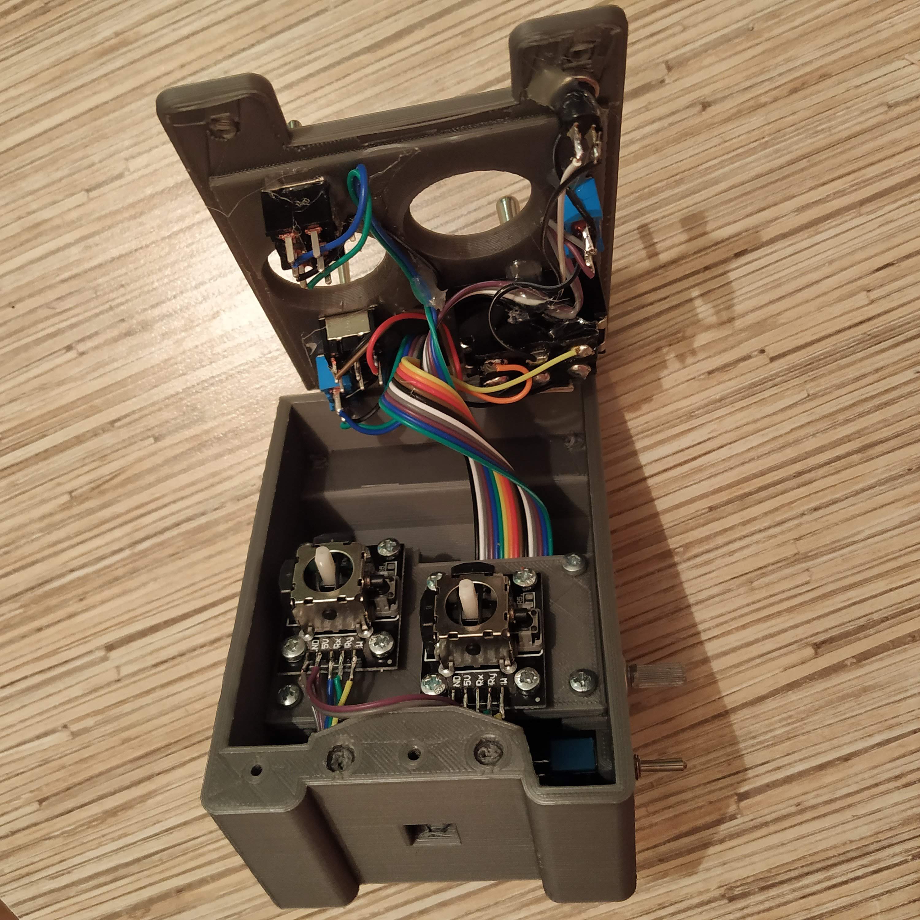
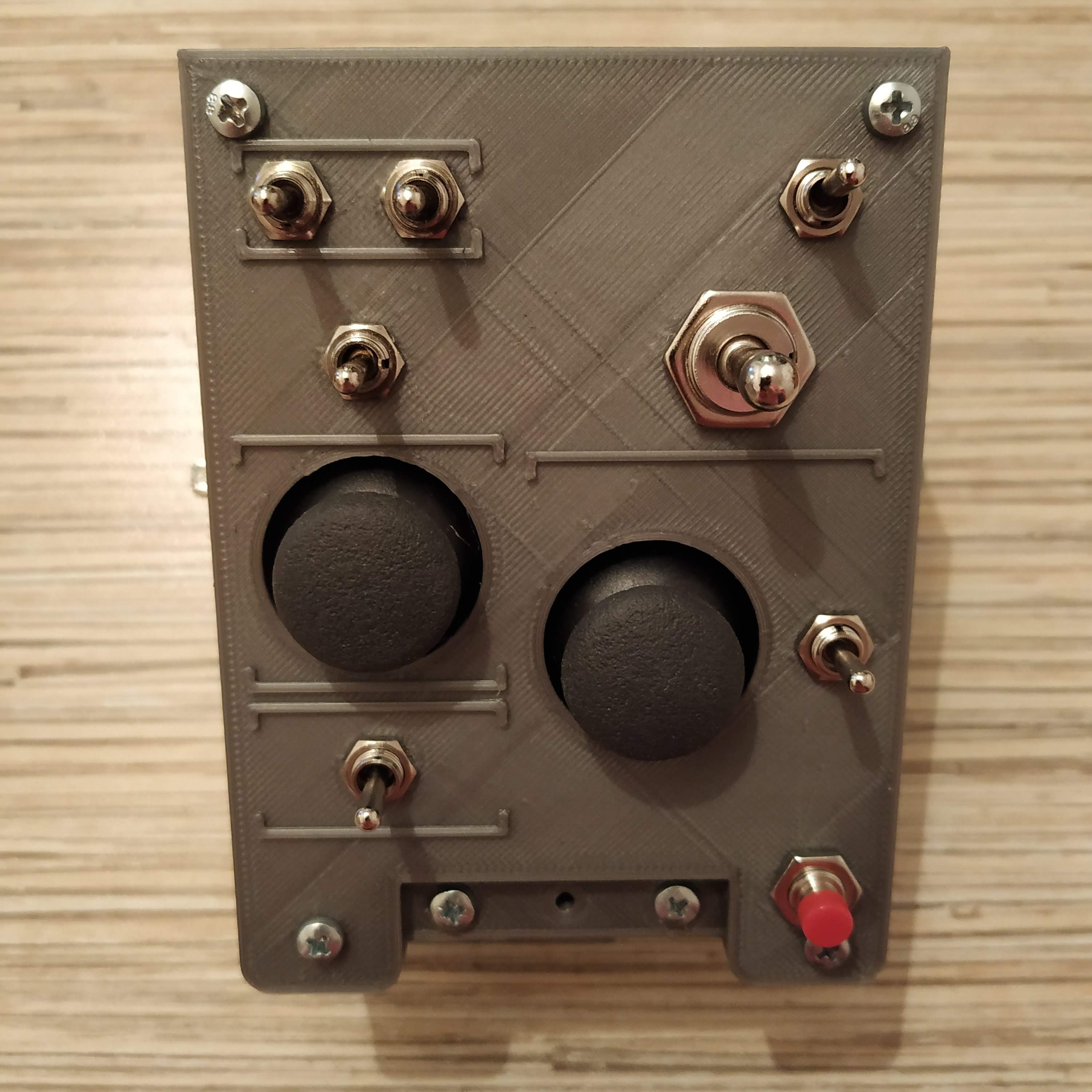
14. If you have chosen the version with rotary pots, do not forget to put knobs onto them.
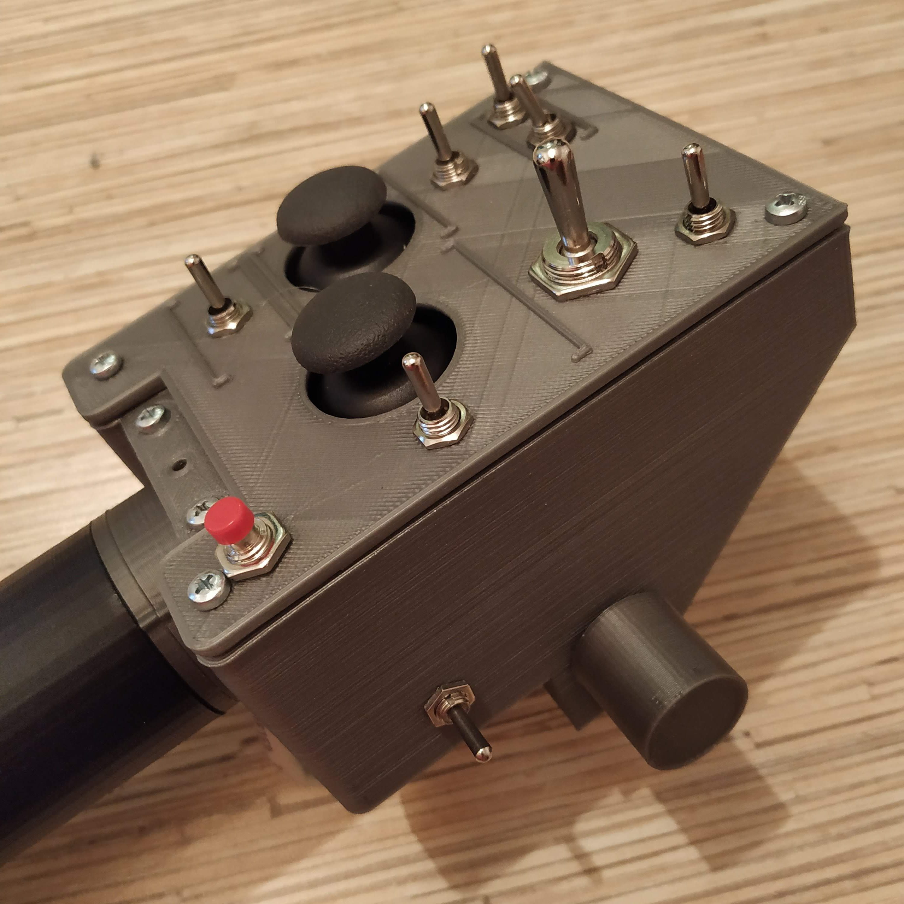
Congratulations, you’ve just assembled the 412collective switch panel! You can try it right away, or read about switch configuration options below.
Congratulations, you’ve just assembled the 412collective switch panel! :)
You can try it right away, or read about switch configuration options below.
Software configuration
Switch modes
Let’s talk about switch modes. They are configured in the master_controller.ino file:
// AB412 switch modes
// write joystick button numbers here as they are displayed in joy.cpl in order of increment
- byte ab412_sw_mode_button_switches[] = {1,2,5,9,10,17}; //active when being held
- byte ab412_sw_mode_toggle_switches[] = {6};//2-way switch mode: single button press when switch is turned to “on”, one more press when switch is turned to “off”; something you can assign to a single key press; e.g. gear extend/retract
- byte ab412_sw_mode_selector_button_switches[] = {}; //3-WAY SWITCHES ONLY, FIRST BUTTON (WITH LOWER NUMBER) MUST BE GIVEN HERE; REMOVE THE SECOND BUTTON FROM EVERYWHERE ELSE FOR CORRECT OPERATION; when a switch is on, a button is held; when off, another button is pressed and held;
- byte ab412_sw_mode_selector_switches[] = {3,5,11,13,15}; //same as above, but buttons are pressed and released – e.g. landing light extend / hold / retract
Comments are pretty much self-explanatory here (i hope).
How to find the button numbers? Just look for them in joy.cpl dialog. You press the button, you see e.g. 17, you write it to the list of the type you want it to be. If you want to assign a 3-way switch to one of the selector types, write the 1st button of it only (with the lower number, e.g. if you have 17 and 18, you write 17 and remove 18 from everywhere else).
Now what the mode switch does, it assigns different sets of joystick buttons to those in the ab412_sw_mode_button_switches[] list. You can choose from several different bottom head part variations: a semi-scale one (no switches or pots on sides), 1 pot, 2 pots, 1 pot + mode switch, 2 pots + mode switch. You can also assign mode switch to any one of the 3-way toggle switches.
Compatibility modes
For some reason, a lot of developers of very detailed and overall great models tend to simplify things, that can be quite minor for the casual simmer, yet quite annoying for hardcore ones. When I have finally finished the collective head, I found that the only heli (from what I have) that more or less works from the box with the collective idle stop switch is the Dreamfoil B407 for X-plane. Yet, my beloved DCS Huey had no support for past-idle stop detent throttle grip movement with an axis! The same thing was to be found out for AB412 which my friends love to fly. Compatibility mode fixes that sad behavior for each popular helicopter model specifically.
For now, DCS UH-1 and AB412 are supported. AB412 requires an additional plugin (FlyWithLua) and a Lua script installation. Please look at this post for detailed instructions. I will be adding support for what I have little by little.
You may always ask me to add support for your favorite helicopter (and/ or sim), but I will need to get it somehow to do that.
That’s it, happy flying!

