Table of Contents
UH-1 Huey Style Collective Head
About Collective Heads
A collective head is a device, that is mounted onto the top of the collective lever to extend its functionality. A few of them are currently available under the MKIV line of hardware.
The recommended default option for flying in VR is the Compact (integrated) collective head (MKVI).
There is a simpler version available, the Simple (integrated) collective head as well as replica ones:
- UH-1 Huey-style collective head (MKVI) (You are currently here)
- Bell206-style collective head (planned)
Summary
This is a UH-1-style collective head. Its dimensions are based on the measurements and photos found on the Internet. It’s almost 1:1 scale. Mode switch is installed in a place of a light bulb, as it’s much more useful in this case. In its default software configuration, it’s set up in a way so you can assign switches of the DCS Huey’s head to it. It can also start a DCS Huey (it will operate it's throttle below idle stop detent). Note: If you’re starting your flight in cold and dark, your throttle should be closed, for this feature to work properly!


Components
Here is the Parts List with all the basic Hardware Parts that you will need for assembling a functioning UH-1 Huey Style Collective Head.
- 1 x PLA plastic coil
- 1 x KY-023 joystick module
- 2 x KN3(B)-223A-A3 or similar switch
- 1 x MTS-103 A-2
- 2 x KN3(B)-203A-A3 or similar switch
- 1 x PBS-16B
- 1 x PBS-10B-2
- 5 x M3x50mm screws
- 1 x M3x35mm screws
- 1 x M3x30MM screws
- 4 x M3x12mm screws
- 4 x M3x10mm screws
- 1 x TJ8-8P8 Ethernet socket
- 1 x Arduino Pro Mini
- springs

- nuts
- ribbon cable
- hot glue gun
Downloads
Assembly guide
1. Carefully remove the supports. Note that inside of the housing there are internal structures that, in theory, can be broken accidentally (though they have been strengthened to avoid that). Press-fit nuts into their sockets on the bottom of the head.


2. Insert switches to the housing cover. Two switches in the bottom should be spring-loaded type ( (ON)-OFF(ON) ), two upper switches – toggle type ( ON-OFF-ON ).


3. Break pin parts with screws off the switches.

4. It’s time to heat up your soldering iron and a glue gun. Put some solder onto contact pads of the switches (don’t forget to use some flux). Be careful – do not overheat switches too much.


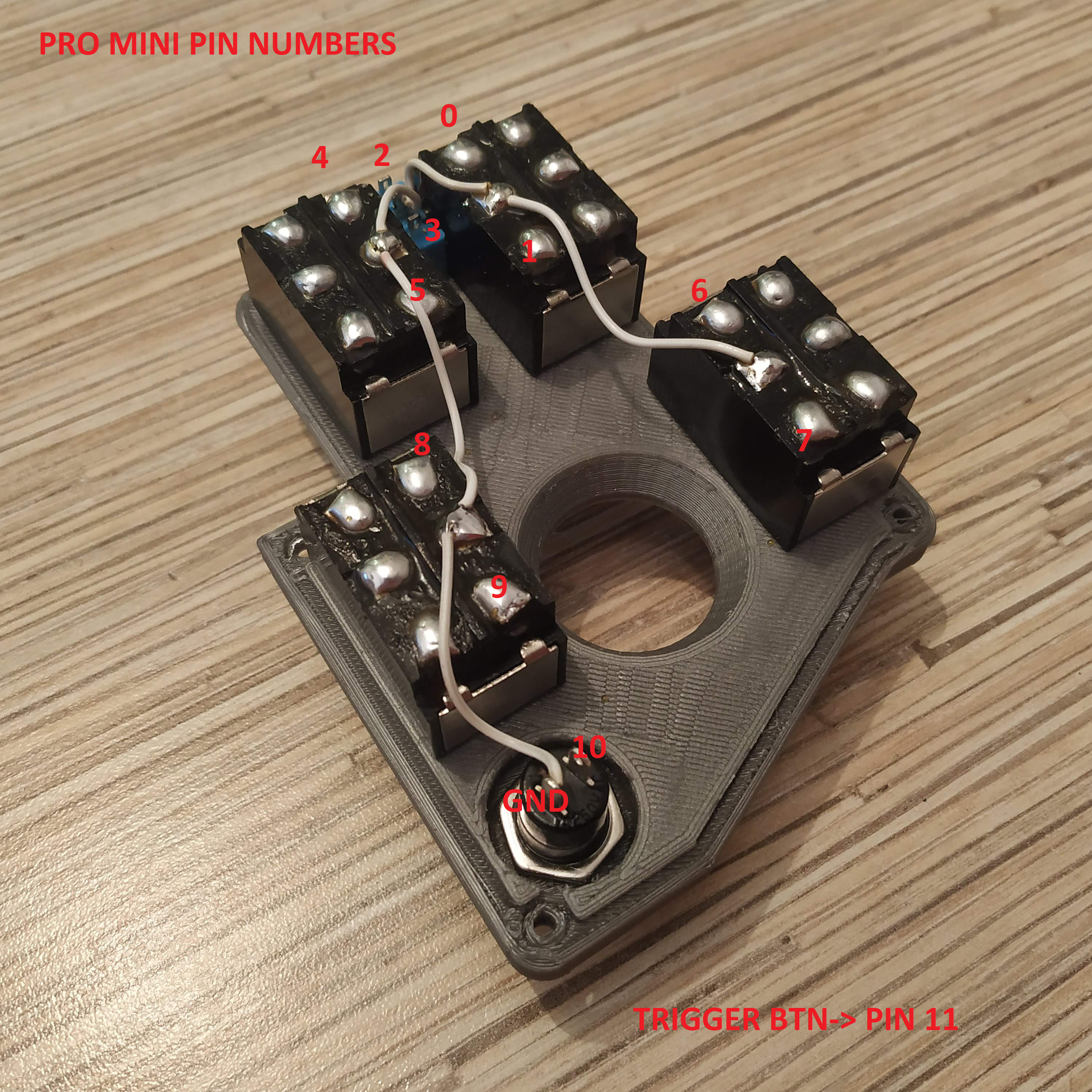
5. Cut a wire off the ribbon cable, and connect ground (middle) pins of the switches and the button together, as shown on the picture below:

6. Cut a 12-wire cable off the ribbon. Solder wires one by one, following numbers on the picture. The last wire will be the ground one. Use the same contact pads row, where the ground wire is.
7. Apply enough hot glue, so it won’t move around.

8. Solder a 5-wire cable, cut off the ribbon to the pot board. Put it onto its frame, fix it in place, with 4x M3x10MM screws.

9. Solder UART header to the Pro Mini.

10. Starting from pin0, solder the 12-wire switches cable to the Pro Mini’s digital pins. The wire of the button should go to pin10, and the last wire of the cable should go to the GND pin, near it.


11. Bend the legs of PBS-10B2 button, as shown on picture, and solder long enough wires to it. Then insert it into its socket in the lower part of the housing. Fix with it's nut (rotate it with pliers, or a blade, as tight as possible). Use tiny drops of hot glue on both sides of the button, to fix it in place.


12. Solder 1st 4 wires of a 7-wire cable to 1st 4 pins of an Ethernet socket. Solder another 3 wires to pins 5-7 for flashing through the Ethernet socket option. (Older photos below, assume a 7-wire cable is used)

13. Press-fit the socket into its slot and check that wires are still connected to the socket with a multimeter. If everything’s ok, pour a fair amount of hot glue to fix it in place.
To make the installation easier:
- Make sure the pins and cables are bent rather flat, so that you have the clearance to slide the socket to its place from the inside.
- Use a screwdriver or similar to apply force and push the socket thru the opening, in the end.
- Applying the hot glue might get tricky, as the crevice is small, use of a tool might be a good idea.


14. Solder one of starter button’s pins (PBS-10B2) to pin11, another one – to the ground. Use a spare GND pin of the UART header on the Pro Mini, or some switch’s central contact pad (the same row where wires are soldered!) at your discretion.

15. Solder pot board wires as follows:
GND→ GND pin next to reset pin
- +5V→ETHERNET SOCKET PIN 1 →ARDUINO VCC pin
- VRx→A0
- VRy→A1
- SW→ PIN12
16. Solder ethernet soket wires as follows:
- SOCKET PIN1 → VCC (should be soldered already after the previous step)
- SOCKET PIN2 → GND
- SOCKET PIN3 → SCL (A5)
- SOCKET PIN4 → SDA (A4)
- SOCKET PIN5 → Rx
- SOCKET PIN6 → Tx
- SOCKET PIN7 → DTR

17. That’s it! Time to flash Pro Mini board! Uncomment “Serial.begin” line and lines under “\\DEBUG” line. When flashing, make sure that all switches are centered.
18. Open serial port monitor in Arduino IDE. You should see something like this:
““00000010 00100000 124 128””
Something around 128 in two last numbers means your potentiometers are connected properly (0 or 255 means there’s a problem!). Flip all switches and press all buttons (including the thumbstick button!), you should see 1s popping up in the line. Note, that the left upper switch in its lower position will temporarily cut off serial port communication, that’s fine. Just flip it back to continue.
19. When you have checked all switches and buttons, proceed to comment out the line: “Serial.begin”, and lines under
“\\DEBUG” line and re-flash the firmware.
20. Put everything together! Use 4x M3x50mm screws for fastening the lid and 4x12mm screws for the pot board frame.
21. Insert the starter trigger, and fix it with an M3x30mm screw. Drill out it's hole, if required, to make it rotate freely. If it's travel range is too short, file the lower edge of its slot (just a bit).
Congratulations, Huey-style collective head is ready for a test flight! :)
