
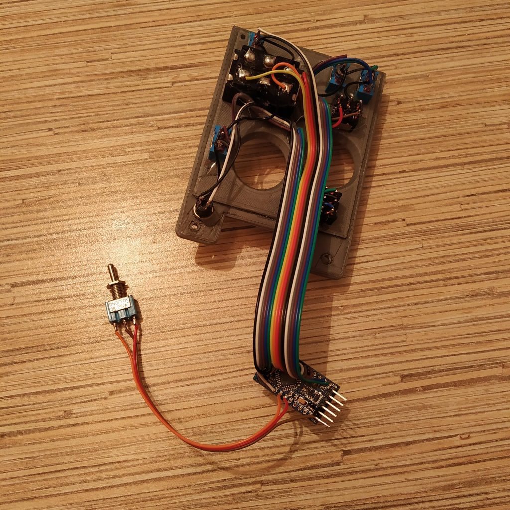
Summary

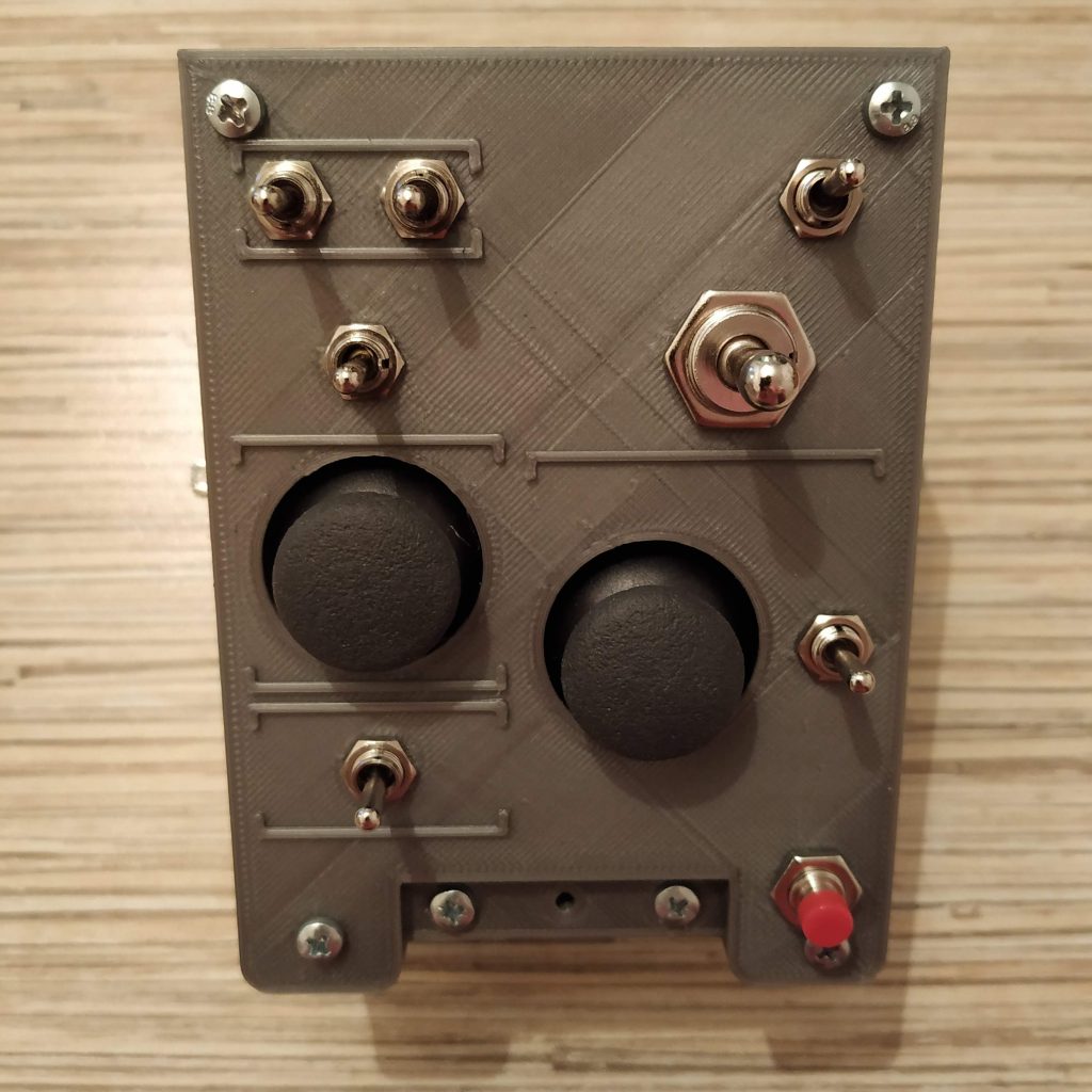
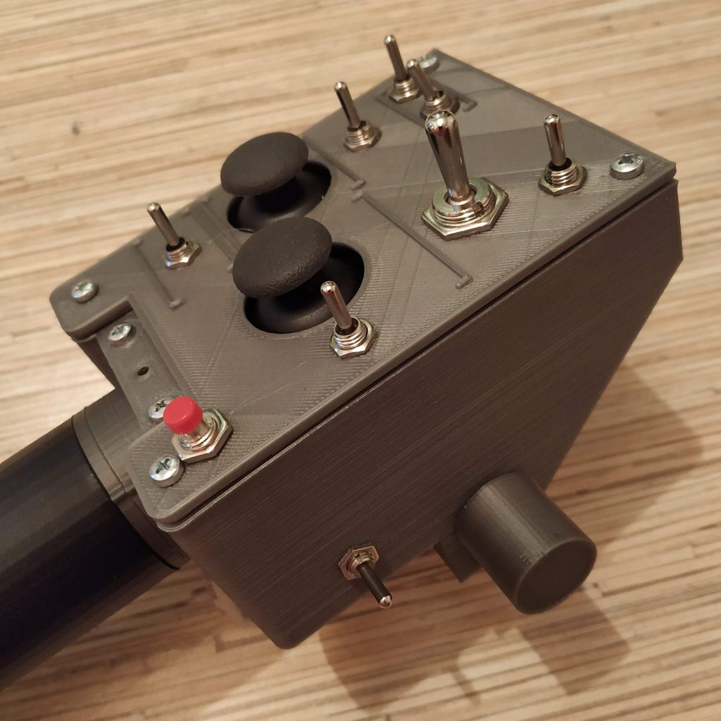
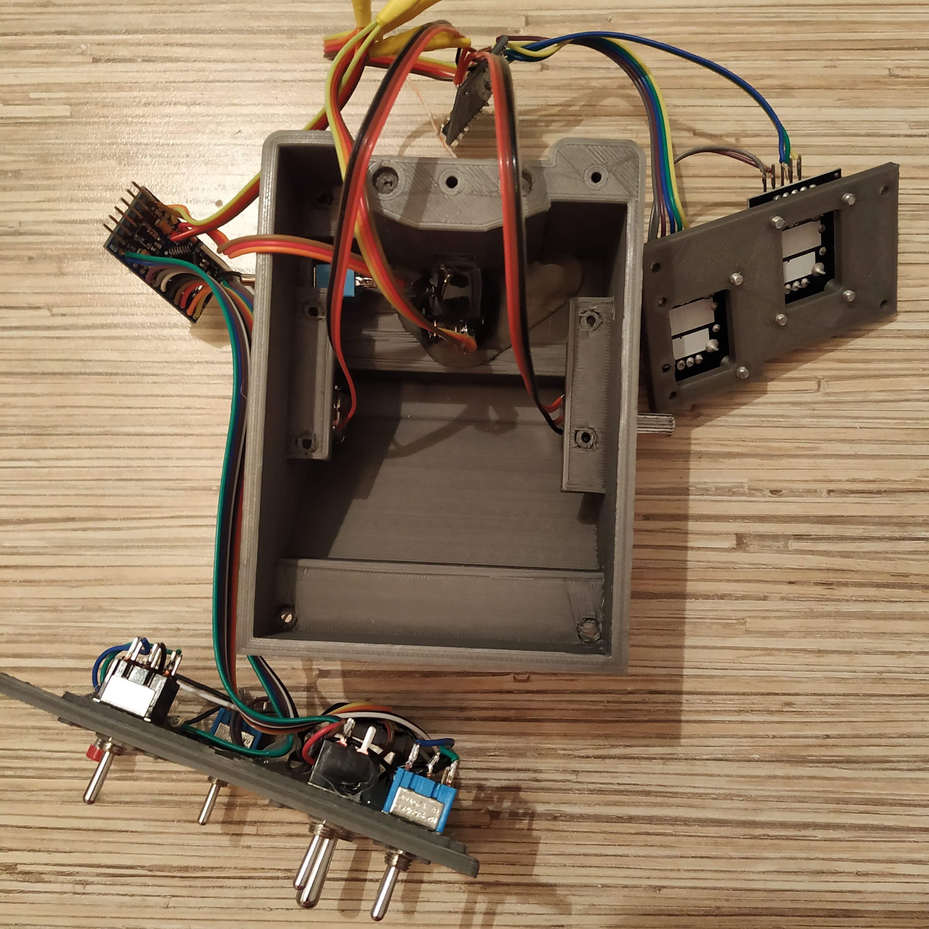
This is the AB412-style collective lever head. It’s not 100% scale, but is close enough and has quite a lot of stuff in it: two Arduino Pro Minis onboard, two hat switches, seven 3-way switches and three buttons on the top panel, and optionally up to two rotary pots on its sides, along with a mode switch. It also has some interesting software-driven features:
- four switch modes to cover all your needs
- you can choose which switches to use: toggle 3-way switches of spring-loaded ones in any combination
- DCS UH-1 idle stop compatibility mode – this thing can realistically start and stop the Huey, although it doesn’t support advancing throttle past idle-stop detent with a joystick axis
- X-Plane X-Trident AB412 idle stop compatibility mode (with an external Lua script)
- mode switch triples your buttons and spring-loaded switches number
Components
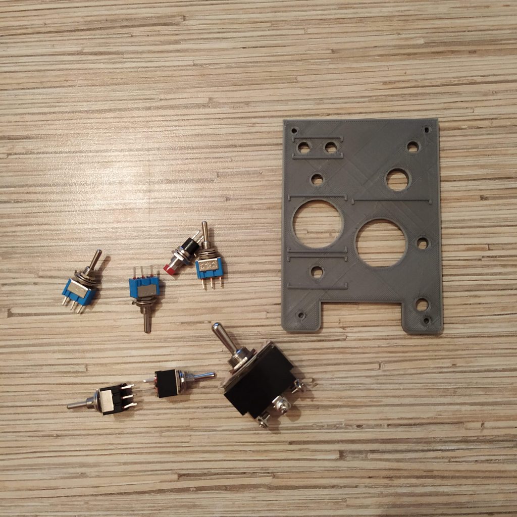
You will need:
2 x Arduino pro mini board
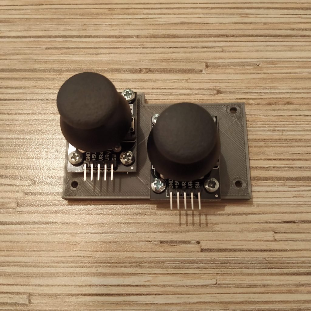
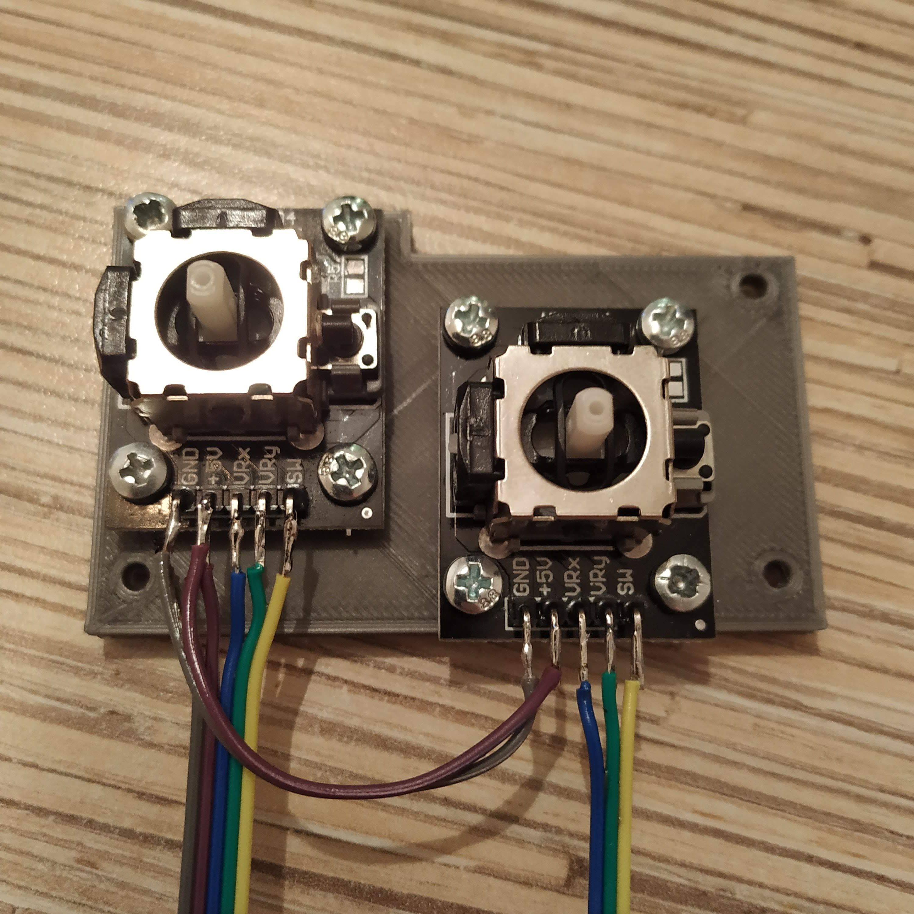
2 x KY-023 joystick module
1 x USBtoCOM adapter (e.g., PL2303) or another Arduino to program it
1 x PBS-10B-2 button
1 x KN3(B)-103A-A3 switch (starter, in a real 412 it seems to be a toggle type switch)
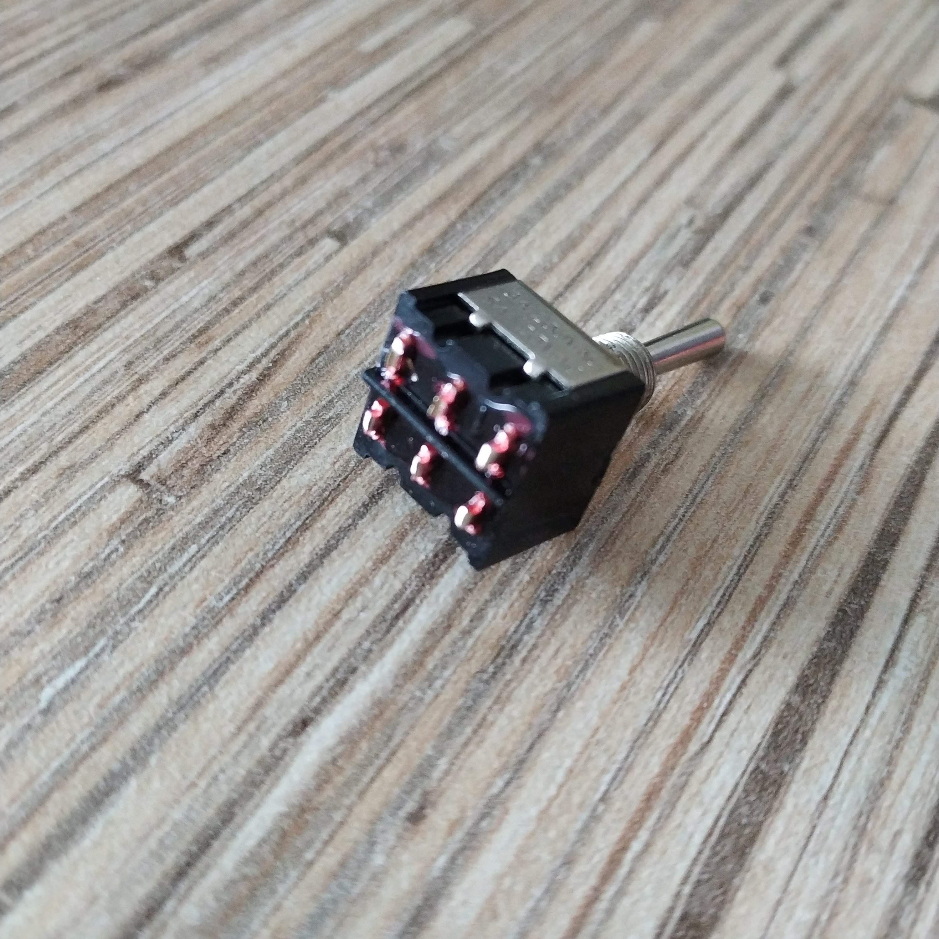
2 to 7 x MTS-223-A2 (ON)-OFF-(ON) spring-loaded switches
0 to 5 MTS-223-A1 ON-OFF-ON toggle type switches
some wires
2 x m3x20 screws and nuts
2 x m3x40 screws and nuts
1 x Simchair MKIII I2C controller (Arduino Leonardo based) (https://www.thingiverse.com/thing:2919692)
1 x Simchair MKIII collective (single or twin-throttle version)
1x TJ8-8P8 ethernet socket
Available mods
- enclosure bottom variants:
– scale version
– 2 side pots and a mode switch
– 2 side pots, no mode switch
– 1 pot, no mode switch
Special features
- XTrident AB412 startup /shutdown support
- DCS Huey startup / shutdown support
- Collective hold (right thumbstick click)
- hat switches support 4-way or 8-way modes
- 4 switch operation modes for every possible use scenario
- mode switch triples the number of switches / buttons configured as pushbuttons
Downloads
STLs / Sources
Mods
Switch controller firmware
Potentiometer controller firmware
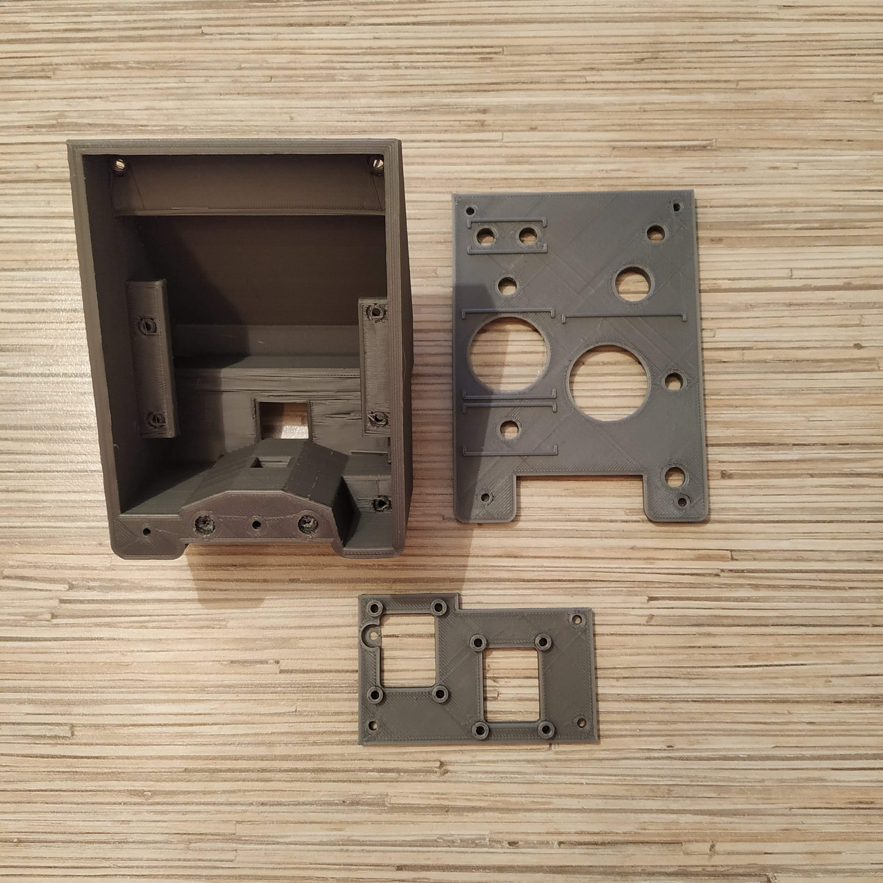
Assembly
- Remove supports from all printed parts. Take a spare piece of square alu pipe and put the head housing onto it several times to ensure a tight, but not overly tight, fit. Press-fit nuts into their sockets.

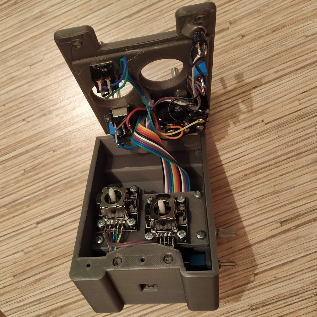
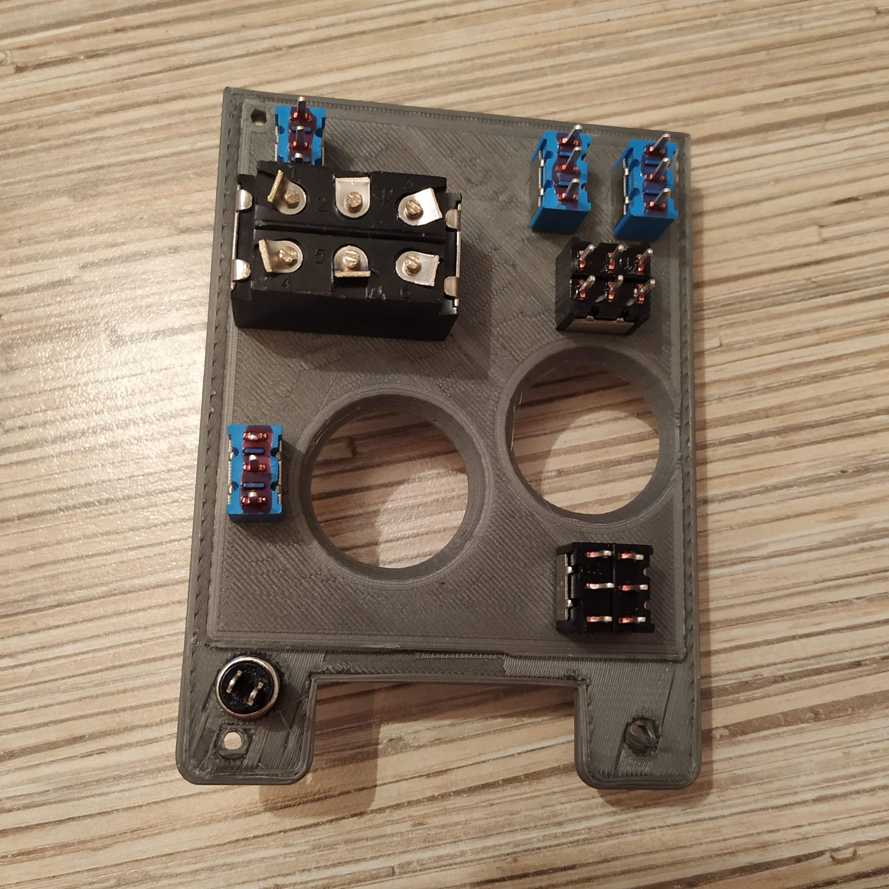
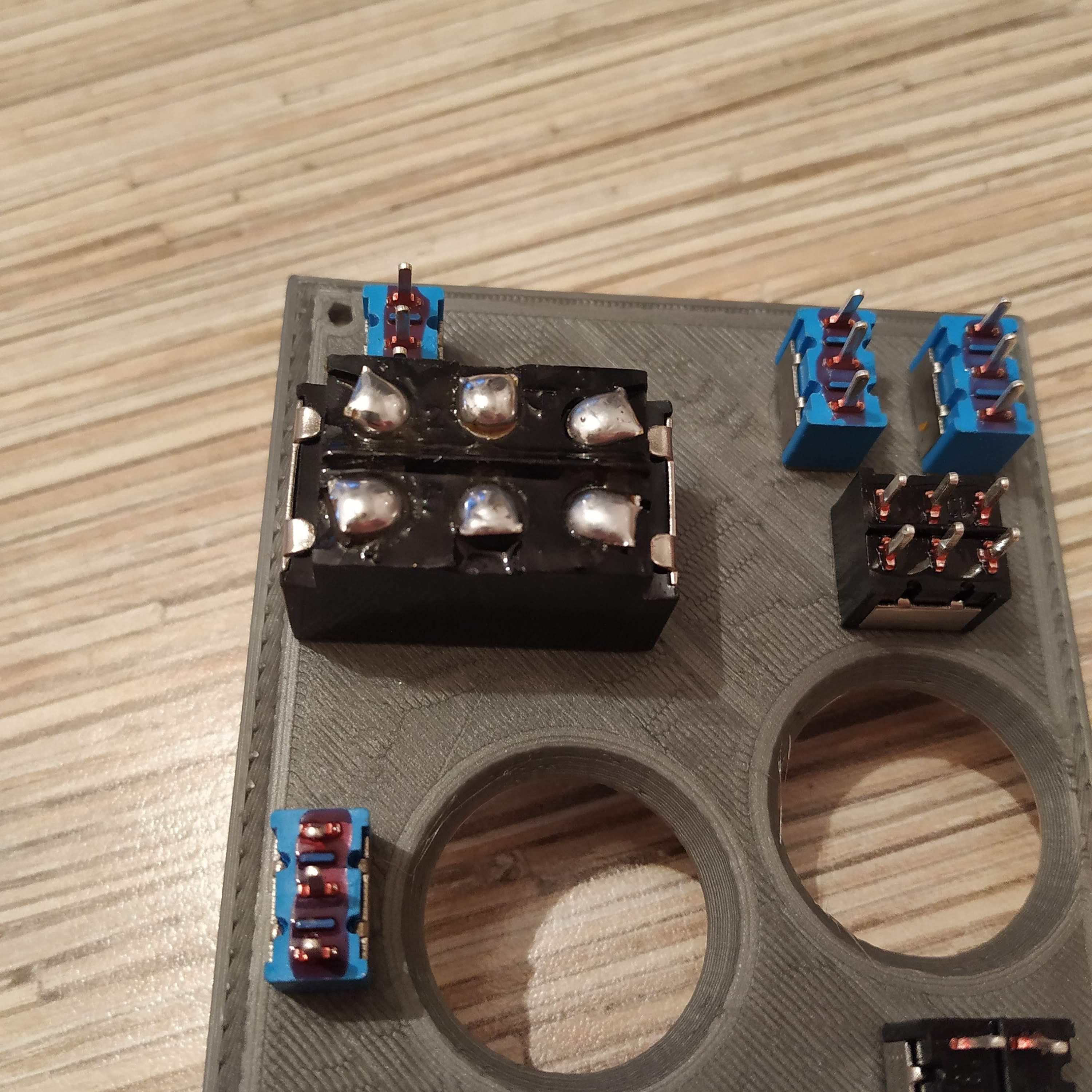
- Insert switches and a button into the top cover. By default, there are two (ON)-OFF-(ON) momentary switches, that go to two lower slots on the left side of the head cover. All others are toggle type – ON-OFF-ON. Switch next to the starter (idle stop) flips sideways.
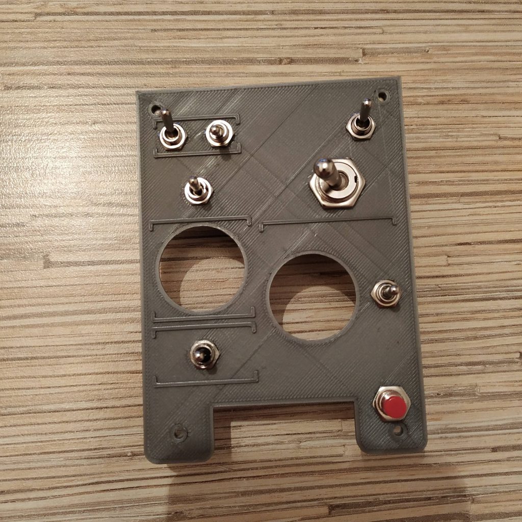
- IMPORTANT FIX: cut legs of the bottom left switch (when viewed from the top (previous picture), face side, the spring-loaded governor switch) short! Otherwise, it will be shorting pins of the KY-083 board under it!

- Break off parts of contact points with screws from a starter switch. Apply some solder to remaining parts of contact pads.


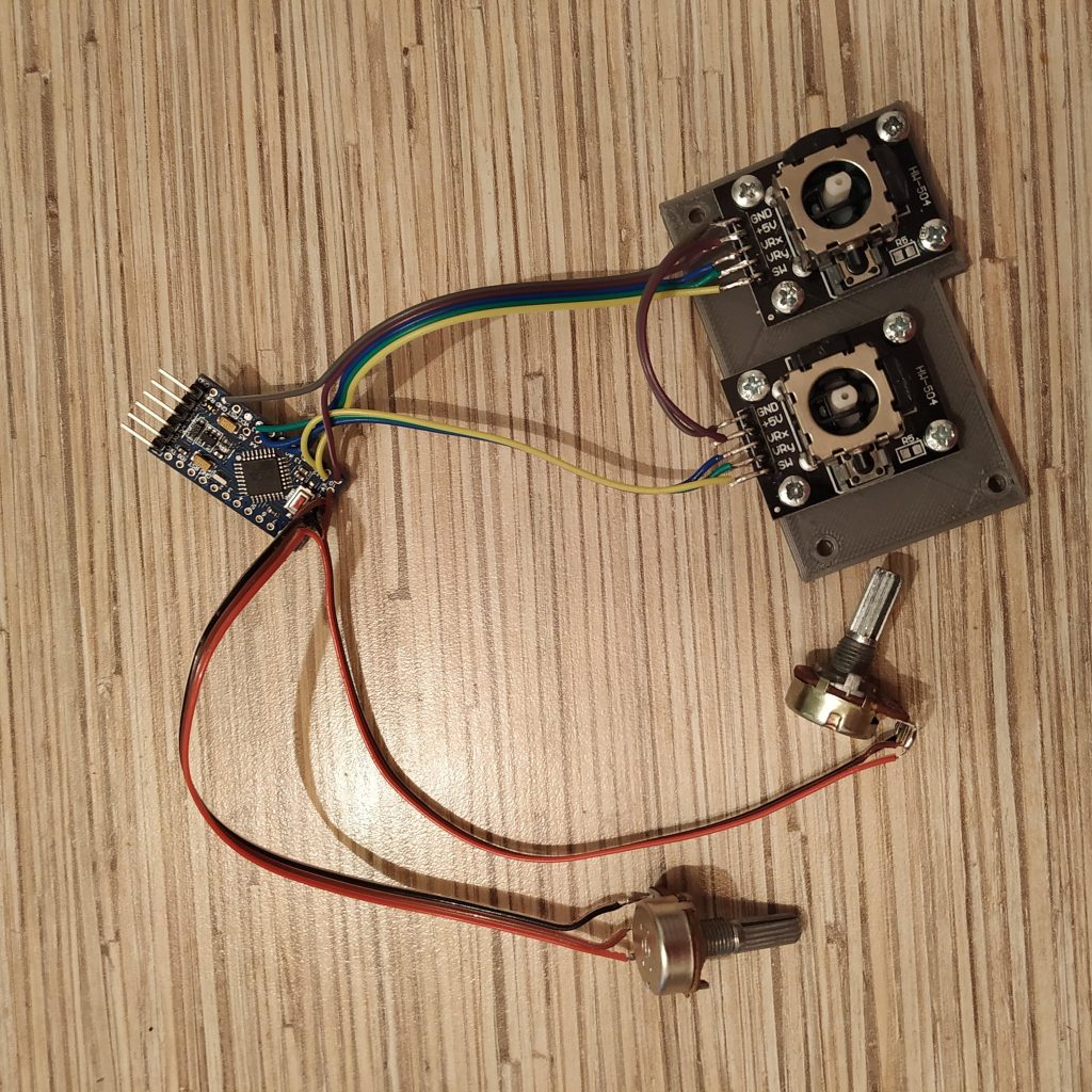
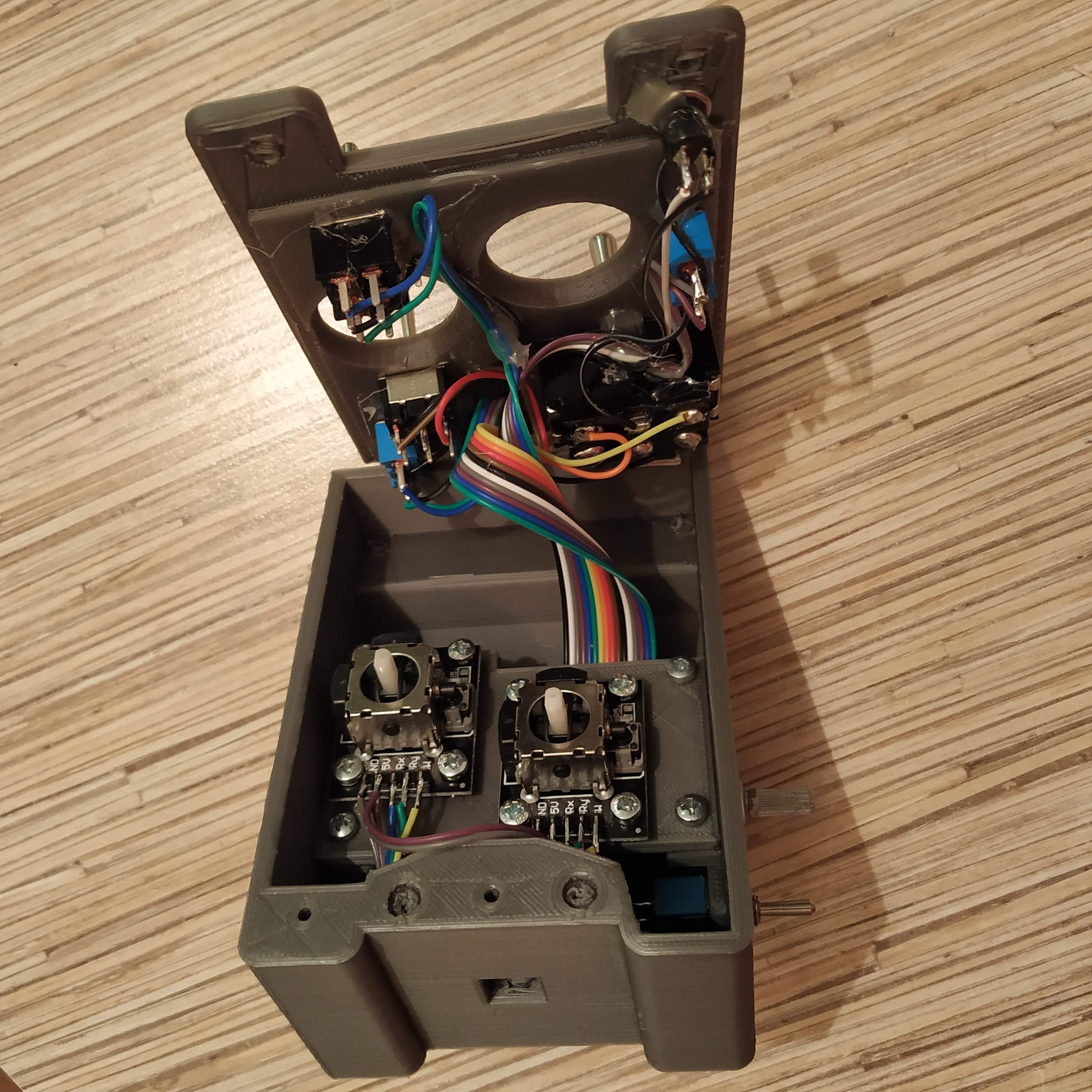
- Now, it’s time to solder ground pins together. Cut 1 wire from the ribbon cable, make cuts in its isolation where needed, and solder it to middle pins of each switch and one of the button pins. Note that for switches with 2 rows of pins, you only need to use 1 row (they are not connected internally). Proper cable routing is very important at this stage.
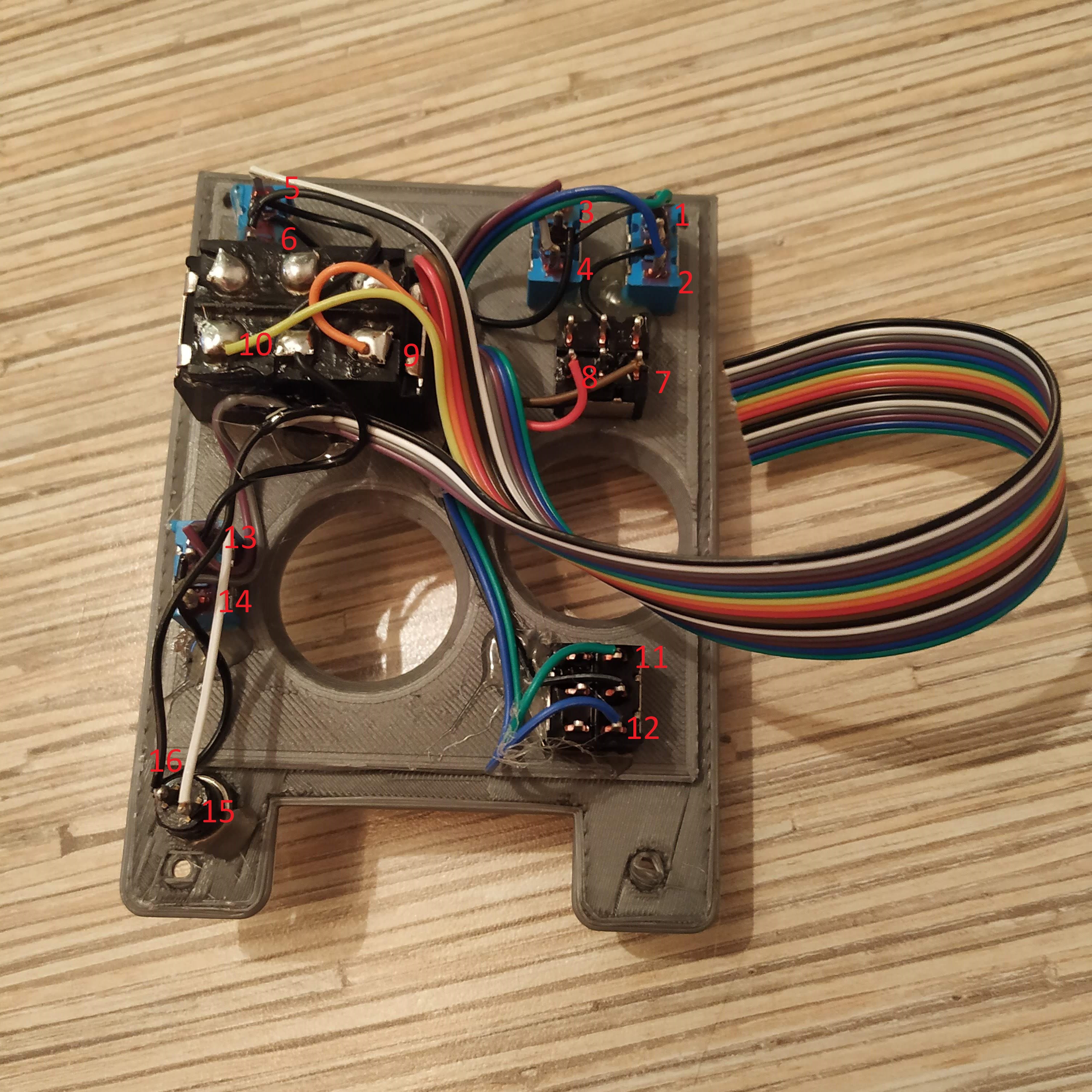
- Cut a 16-wire cable off the ribbon cable. Position the head cover so the little red button will be on the bottom. Turn the cover and start soldering wires, 1st wire to the upper contact point of the 1st switch from the right, 2nd wire to its lower contact point, 3rd wire to the upper contact point of the next switch to the left in the same row, and so on until everything will be connected. Switches flipping sideways should be soldered starting from their rightmost contact point. The last wire goes to ground. When finished, secure everything in place with hot glue. Please consult with the picture below.
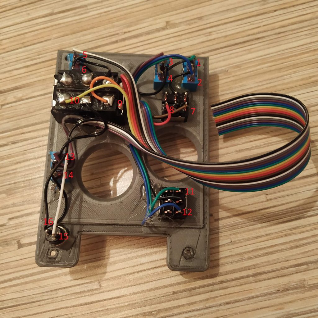
- Now it’s time to solder another end of the 16-wire cable to an Arduino pro mini (solder a UART header to it first). Start from pin0,(top-right switch upper contact pad should go there) and solder all wires one by one. Remove the led, connected to pin 13 (you can find it next to pin 9). The 11th wire goes to pin 10. The 15th wire will go into A0 pin, that’s ok. The 16th wire goes to a GND pin.
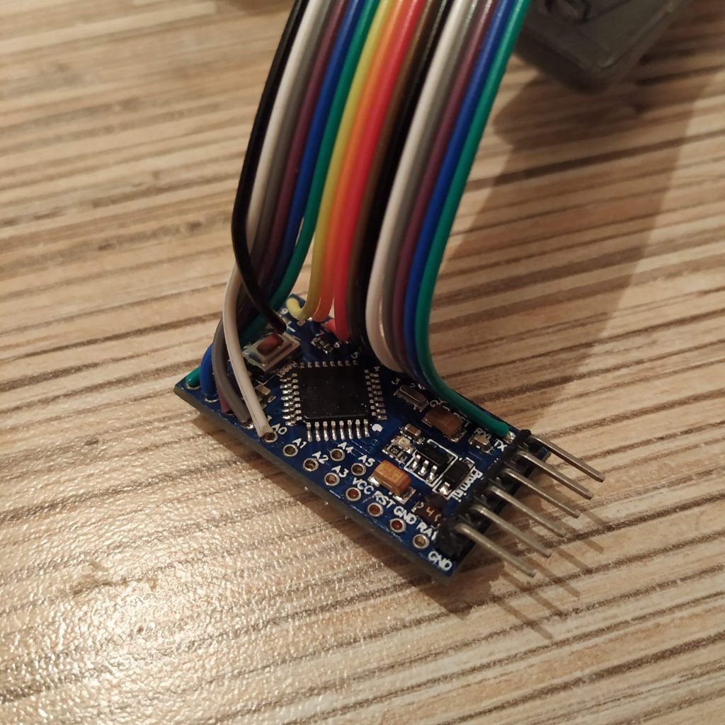
- Cut a 3-wire cable from a ribbon and solder it to the mode switch. Connect its signal wires to pins A1 and A2. Solder the pot’s ground to the outermost GND pin on UART header. The switch controller is now assembled!
- Let’s move on to the pot controller. Attach pot boards to their frame, pins facing backward, with 8 M3x6mm screws. (or you can use 2 M3x6mm screws on the left side and 10mm screws elsewhere) .
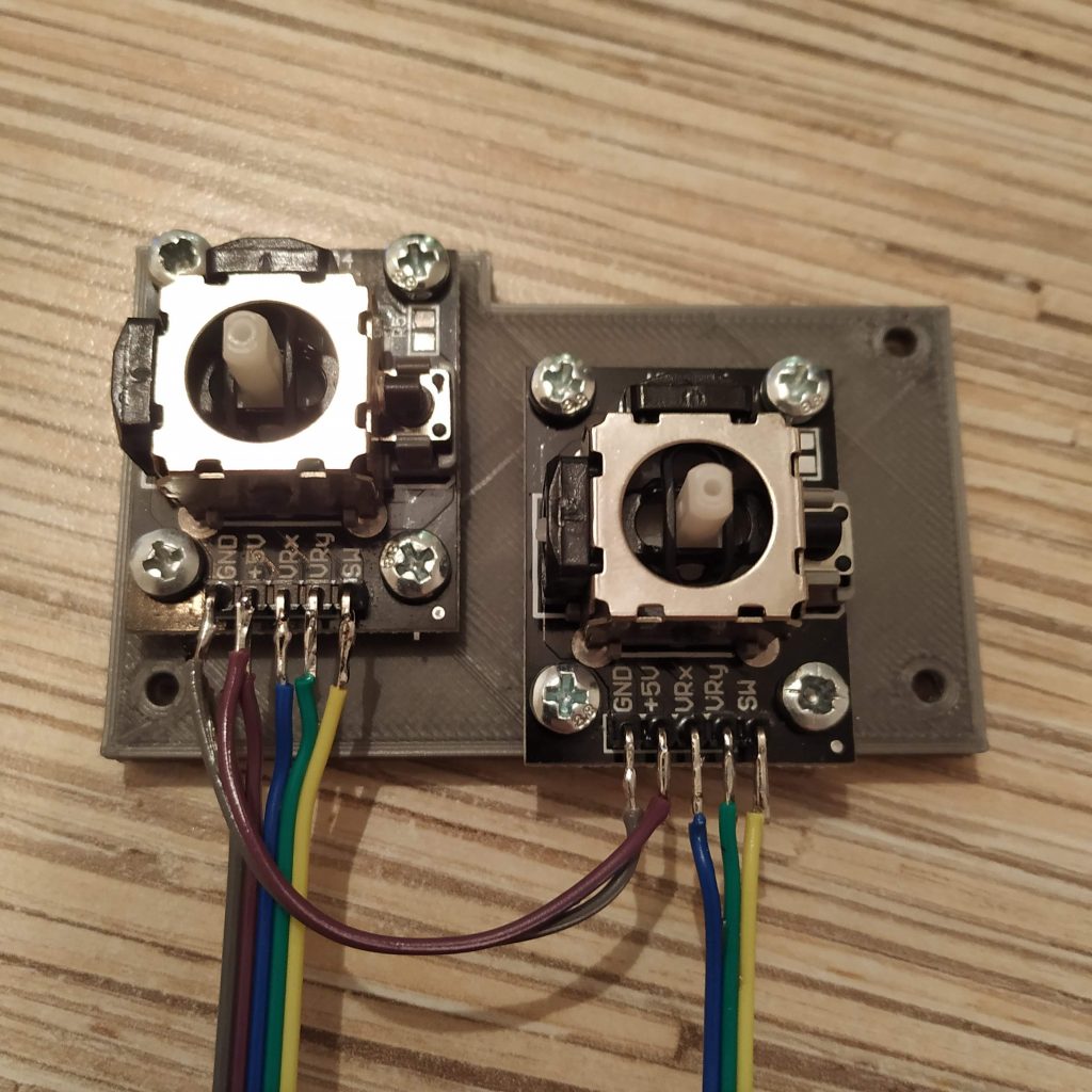
- Solder wires to pot boards and connect them as follows:
POT BOARD 1 VCC -> POT BOARD 2 VCC -> PIN 10
POT BOARD 1 GND -> POT BOARD 2 GND -> GND
POT BOARD 1 VRx -> A0
POT BOARD 1 VRy -> A1
POT BOARD 2 VRx -> A2
POT BOARD 2 VRy -> A3
OT BOARD 1 SW -> PIN 11
POT BOARD 2 SW -> PIN 12
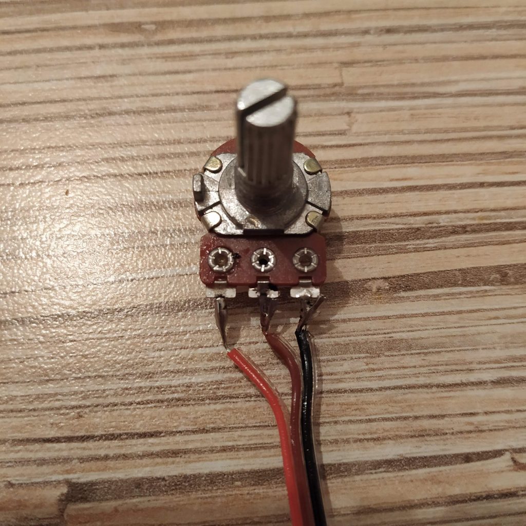
ROTARY POT 1 VCC -> ROTARY POT 2 VCC -> PIN9
ROTARY POT 1 GND -> ROTARY POT 2 GND -> GND
ROTARY POT 1 SIGNAL -> A6 (5V on the left leg of the pot facing up)
ROTARY POT 2 SIGNAL -> A7
The pot board is now assembled!
- It’s time to connect everything with the I2C bus. Solder 4wires to 1st 4 pins of an ethernet socket, then connect them to both boards as follows:
SWITCH CONTROLLER VCC -> POT CONTROLLER VCC -> Tj8-8P8 PIN 1
SWITCH CONTROLLER GND -> POT CONTROLLER GND -> Tj8-8P8 PIN 2
SWITCH CONTROLLER A4(SCL) -> POT CONTROLLER A4 (SCL) -> Tj8-8P8 PIN 3
SWITCH CONTROLLER A4 (SDA) -> POT CONTROLLER A4 (SDA) -> Tj8-8P8 PIN 4 - Electronics is finally assembled! Now, we need to flash Arduino boards and test everything. At first, connect a USB-UART adapter to boards and flash them with their corresponding firmware. You can uncomment Serial.prints to test switches (NOTE THAT ALL SWITCHES SHOULD BE CENTERED, YOU MAY NEED TO PRESS RESET MANUALLY DURING FLASHING PROCESS). When you press something, a “1” should turn on somewhere. After all, switches are tested, comment out “Serial.prints”, reflash the board, connect the ethernet socket to Simchair MKIII I2C controller and check that the collective head is recognized. Collective heads register as the 3rd “Arduino Leonardo” in the list.
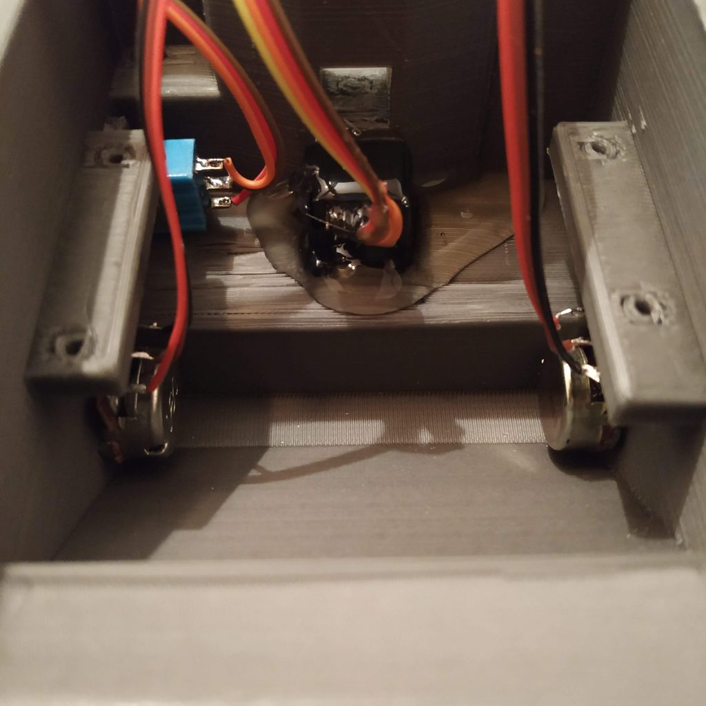
- Let’s put the stuff into the box. Start with inserting the ethernet socket. Secure it with a fair amount of hot glue. Put rotary pot 1 to the right side of the lever (relative to its normal position in a helicopter), rotary pot 2 to the left side, mode switch facing upwards with wire, connected to A1 pin.

- If you have chosen the version with rotary pots, do not forget to put knobs onto them.


Congratulations, you’ve just assembled the 412collective switch panel! You can try it right away, or read about switch configuration options below.
Software configuration
Switch modes
Let’s talk about switch modes. They are configured in the master_controller.ino file:
| // AB412 switch modes |
| // write joystick button numbers here as they are displayed in joy.cpl in order of increment |
| byte ab412_sw_mode_button_switches[] = {1,2,5,9,10,17}; //active when being held |
| byte ab412_sw_mode_toggle_switches[] = {6};//2-way switch mode: single button press when switch is turned to “on”, one more press when switch is turned to “off”; something you can assign to a single key press; e.g. gear extend/retract |
| byte ab412_sw_mode_selector_button_switches[] = {}; //3-WAY SWITCHES ONLY, FIRST BUTTON (WITH LOWER NUMBER) MUST BE GIVEN HERE; REMOVE THE SECOND BUTTON FROM EVERYWHERE ELSE FOR CORRECT OPERATION; when a switch is on, a button is held; when off, another button is pressed and held; |
byte ab412_sw_mode_selector_switches[] = {3,5,11,13,15}; //same as above, but buttons are pressed and released – e.g. landing light extend / hold / retract
Comments are pretty much self-explanatory here (i hope).
How to find the button numbers? Just look for them in joy.cpl dialog. You press the button, you see e.g. 17, you write it to the list of the type you want it to be. If you want to assign a 3-way switch to one of the selector types, write the 1st button of it only (with the lower number, e.g. if you have 17 and 18, you write 17 and remove 18 from everywhere else).
Now what the mode switch does, it assigns different sets of joystick buttons to those in the ab412_sw_mode_button_switches[] list. You can choose from several different bottom head part variations: a semi-scale one (no switches or pots on sides), 1 pot, 2 pots, 1 pot + mode switch, 2 pots + mode switch. You can also assign mode switch to any one of the 3-way toggle switches.
Compatibility modes
For some reason, a lot of developers of very detailed and overall great models tend to simplify things, that can be quite minor for the casual simmer, yet quite annoying for hardcore ones. When I have finally finished the collective head, I found that the only heli (from what I have) that more or less works from the box with the collective idle stop switch is the Dreamfoil B407 for X-plane. Yet, my beloved DCS Huey had no support for past-idle stop detent throttle grip movement with an axis! The same thing was to be found out for AB412 which my friends love to fly. Compatibility mode fixes that sad behavior for each popular helicopter model specifically.
For now, DCS UH-1 and AB412 are supported. AB412 requires an additional plugin (FlyWithLua) and a Lua script installation. Please look at this post for detailed instructions. I will be adding support for what I have little by little.
You may always ask me to add support for your favorite helicopter (and/ or sim), but I will need to get it somehow to do that.
That’s it, happy flying!
Download links
Check out the latest software on GitHub
Hi! I have now started concentrating my work on creating an AB412 head, but as I am trying to get my head around this project I am having some questions. I hope you can help me with this like you helped me with the collective:
1) I think I found a typo:
“SWITCH CONTROLLER A45(SCL) -> POT CONTROLLER A4 (SCL) -> Tj8-8P8 PIN 3”
should probably read
“SWITCH CONTROLLER A5(SCL) -> POT CONTROLLER A5 (SCL) -> Tj8-8P8 PIN 3”
2) To avoid the stupid problems I had with the collective electronics, I made another crude schematic of the pot controller board. Is this the correct way to wire it? Link: https://imgur.com/eMuIqdI
3) I am a bit puzzled by the wording in the description of the switches controller. Does it mean that I:
3a) Start by connecting all middle pins of all switches (as well as one “leg” of the button) to GND on the board
3b) Then connect outer pins of switch 1 in the uppermost row to PIN0 and PIN1
3c) Then connect outer pins of switch 2 in the uppermost row to PIN2 and PIN3
3d) And so on, continuing with the rows one after the other
4) Where is the second rotary potentiometer located on the AB412 head? I can’t see it on any of the pictures you showed me.
5) Where should the second “leg” of the button be connected to?
6) I am not sure what this line means and entails “BE SURE TO REMOVE LED ON PIN 13!”. Do I need to physically remove/desolder the LED? What exactely am I supposed to do and how?
Sorry for turning up again with so many questions! Have a nice day!
1) yup, there’s a typo, will fix it =)
2) looks good. You can also wire all 5v together, then solder the tie to the VCC pin on an Arduino board with a single wire =)
3) Take a single wire. It will be the ground one. Connect all the middle pins together (if a switch has 2 rows of contacts on it – only use one) with it (start from the TOGA button and go around, for example)? then connect it to Arduino’s GND. Then look at the switches on the head: start from top-left one (when you turn the head to solder wires it will be the top right one), from the outermost contact of it, it should go to pin0. Its bottom contact will go to pin1. Then go to the next one in the same row, start with its outermost contact, etc. I recommend using this switch order so you won’t need to mess with reassigning buttons for some special functions on software update =)
4) Side potentiometers are optional! You can use the semi-scale version without them, or a version with one pot on the right side, or a 2-pot version (pots on right and left walls of the head, all of them are under mods folder). Same for the mode switch, you can use any of the switches on top for it (but I think it’s better to have one on the side =) )
5) Whether its a button or a switch, there’s no difference (a switch is basically 2 buttons), just connect it to a pin, following the common connection pattern from top to bottom, left to right.
6) yup, that’s important, desolder it, otherwise, button 13 will be always pressed =) Just carefully touch it with a soldering iron, be sure that it’s mounting pads are not connected after desoldering (it’s an SMD one, doesn’t need much heat to come off).
Btw pin 3 on a TJ8P8C socket means the one where the green-white wire goes in an ethernet cable.
It’s fine =)
Hello again!
Thank for your helpful hints! I was very busy lately and could not find any free time to continue (or fly with my new collective….). But recently I had a few minutes and managed to progress (see my gallery update: https://imgur.com/a/ExZKnbT ).
Now I am finally ready to tackle the mounting of the electronic parts. And yet again I have questions.
1) Where would you mount the second potentiometer? I am not sure If I want to but I would love to know.
2) Are those switches momentary switches (return to center because of spring) or regular ones (A-0-B, don’treturn to center)?
All the best!
Hey there! Your 412 head looks great!
1) For the second pot, there’s a modified version of the enclosure (under mods directory):
https://github.com/hc625ma/simchair_models/blob/master/Mods/Peripherals/AB412%20collective%20head/STL/ab412_head_enclosure_p1_2_rotary_pots_mode_switch_ab412_head01c.STL
Don’t worry, yours is perfectly fine, reaching the pot on the left in flight is a bit problematic =)
2) That’s what’s cool about open source stuff: you can use any of them in any combination. The only thing – I recommend using 3-way switches everywhere (you can always make a 3-way switch behave like a 2-way, but not the other way).
I have to note here that you have to follow the wiring scheme (buttons order) precisely to avoid pain with assigning buttons later =)
Firmware supports 4 switch modes for now. They are:
– regular pushbutton (joystick button is pressed when the physical button is being held or the switch is on)
– toggle mode (joystick button is pressed for a moment when you flip a switch, then the same button is pressed again when you return the switch to its center position) example: gear up/down (or anything that can be assigned to a single button press).
These are two basic modes that would be sufficient in most cases. Now, there are 2 advanced modes:
– selector_button (same as a pushbutton, but has a joystick button in the middle) example – searchlight (or landing light, don’t remember which one of them exactly) switch in DCS Huey. In this mode, one of the joystick buttons is ALWAYS pressed.
– selector (same as selector_button, but joystick buttons will be pressed for a moment and released)
Let’s talk about how you assign switches to one of four modes.
In the configuration section of the master controller sketch, there are 4 lists (arrays), where you put joystick button numbers as seen in joy.cpl in mode 0. For 1st two modes, you put each button you want to be assigned to the list. For 2 advanced modes, you ONLY put the 1st button of the switch (the one with the lower number, e.g. if your switch is buttons 3 and 4, you put 3 there and remove 4 from everywhere else!)
Example:
byte ab412_sw_mode_button_switches[] = {1,2,9,10,11,12,17};
byte ab412_sw_mode_toggle_switches[] = {3,4,5,6,7,8};
byte ab412_sw_mode_selector_button_switches[] = {13}; //3-WAY SWITCHES ONLY, FIRST BUTTON (WITH LOWER NUMBER) MUST BE GIVEN HERE; REMOVE THE SECOND BUTTON FROM EVERYWHERE ELSE FOR CORRECT OPERATION
byte ab412_sw_mode_selector_switches[] = {15};
This is a default config that kinda shows how stuff works. I recommend using something like Pointy’s joystick tester (http://www.planetpointy.co.uk/joystick-test-application/) to see all the buttons, as joy.cpl only sees 1st 32 =)
Now, there’s the mode switch (a special little one). You can assign any switch as a mode switch. This switch controls which (of three) joystick button set is mapped to physical switches at the moment. Three sets have 32 buttons each. The middle position of the switch maps joystick buttons 0-32 to physical switches, other 2 positions – buttons 32-64 and 64-96.
Note, that mode switch ONLY works for buttons, that are configured either as pushbuttons (or selector_buttons).
That’s because logically, one would usually configure spring-loaded switches or buttons as pushbuttons (imagine you have flipped the gear position switch to “up”, then switched a mode from 0 (middle) to 1 (up), and have something assigned to the same switch in mode 1. Now, before switching to mode 0 where your gear switch is still up, you have to return it back to “up” position in mode 1 as well, which pretty much kills all the point of using the mode switch with non-spring loaded switches).
Then, there’s a VERY advanced selector_button type use scenario, that I think you wouldn’t likely be using, but it’s here if you need it:
You can switch modes while holding a button! What will happen, is an associated joystick button in a mode where you have pressed the physical button initially, will remain held (let’s say, mode 1). You can now use the same switch in another mode (mode 2 for example), and when you will switch back to mode 1 again, the joystick button will remain pressed. Now, to release it, you have to press that button again.
Now, there is also stuff called compatibility mode. This is basically a set of crutches for DCS Huey and Xplane 11 AB412, that allows performing an (almost) proper startup procedure (connect external power before startup to make it more realistic). These special functions only work in mode switch position 0 (412 also requires some additional LUA scripts to be loaded). When flying other aircraft, if these functions interfere with controls, you can just use modes 1 or 2 when assigning buttons, or disable compatibility mode in firmware.
It can be a little confusing at first, try watching this video where I tried to explain it:
https://youtu.be/dhYm1QeEzdM
Wow, thank 1000 times for the improved description and the great photos! Now everything is absolutely clear and understandable!
Also: That indepth explanation is the motherload of information. Will take me a few readthroughs until I get it all. Thank you!
You’re welcome! The problem with manuals is, you can only write a decent one in the process of assembling stuff =)
Hi Alexey – currently I am working on an AIRBUS H145 collectice – hardware is almost finished. As I wanted to be as close as possible to the original I use for the trim, landing light, search light …. 5-way SMD switches ( beeper function) and I have no need for the KY-023 joystick modules as you used for the AB412 head. As I have now more than 20 switches I would need 2 Arduino Pro minis with all digital inputs only. What do I have to change in your software or is it very simple and I can use for both pro minis the same software?
Hope you can help me!
Guido
Hi Guido!
It’s an interesting question. While technically, it’s not a problem, some code may need to be rewritten or optimized. You can use all ports of Arduino Pro Mini (including analog ones) to connect buttons.
Basically, all you need is to copy the “ab412_switch_controller.ino” file to another file, and to give it another i2c address (e.g. 22) and simply modify the master controller sketch to read it after it reads the 1st one.
Here’s where reading happens:
Wire.requestFrom(13, 3);

  while (Wire.available())

  {

    byte b1 = Wire.read(); // receive a byte as character

    byte b2 = Wire.read();

    byte b3 = Wire.read();
s0 = b1;
s1 = b2;
s2 = b3;
}
if (AB412_COLL_HEAD_ROTARY_POTS == 0)
{
z = 0;
rz = 0;
}
else if (AB412_COLL_HEAD_ROTARY_POTS == 1)
{
rz = 0;
}
int16_t hat0_val = parse_hat_sw(x, y,AB412_COLL_HEAD_LEFT_HAT_DIRECTIONS);
simchair_aux2.setHatSwitch(0, hat0_val);
int16_t hat1_val = parse_hat_sw(rx, ry, AB412_COLL_HEAD_RIGHT_HAT_DIRECTIONS);
simchair_aux1.setHatSwitch(0, hat1_val);
coll_head_parse_switches(s0, 2, 0);
coll_head_parse_switches(s1, 10, 0);
coll_head_parse_switches(s2, 18, 0);
simchair_aux2.setRxAxis(z);
simchair_aux2.setRyAxis(rz);
}
you can see we’re reading 3 bytes, where each bit represents a button state.
coll_head_parse_switches() – this particular piece of code is not the one I am particularly proud of, lol. What it does, is assigns physical switch presses to joystick buttons, taking mode switch and special functions into consideration. Basically, It needs 96 joystick buttons to work (a separate joystick instance), and 4 boolean arrays (length 30 should work). That’s where the sketch can become too large to fit the board =(
You can try using 1st joystick buttons and remove the second one – this will free some memory, or you can try simply adding 4 more arrays and use the 2nd joystick instance to output button presses.
Anyway, try it! Learning Arduino is fun.
If you don’t need mode switch functionality, you can look into what this function does (under z_shared_functions.ino) and simplify it to only use 32 buttons. This way you will easily be able to pack all your buttons into a single joystick instance. Be aware though, that some games may not support more than 32 buttons.
I will try to test it for you and improve this code to allow for more buttons, can take a few days though =)
Alternatively, you can just use some of the buttons as hat switches!
Here’s how it is done for axes:
int parse_hat_sw (int x, int y, byte dirs)
{
int hat_val;
if (dirs == 8)
{
if (y > 145)
{
if (x > 145)
{
hat_val = 45;
}
else if (x < 105) { hat_val = 315; } else { hat_val = 0; } } else if (y < 105) { if (x > 160)
{
hat_val = 135;
}
else if (x < 105) { hat_val = 225; } else { hat_val = 180; } } else if (x > 145)
{
hat_val = 90;
}
else if (x < 105) { hat_val = 270; } else { hat_val = JOYSTICK_HATSWITCH_RELEASE; } } else { if (y > 145)
{
hat_val = 0;
}
…
else
{
hat_val = JOYSTICK_HATSWITCH_RELEASE;
}
}
return hat_val;
}
then later in code:
int16_t hat0_val = parse_hat_sw(x, y,AB412_COLL_HEAD_LEFT_HAT_DIRECTIONS);
With buttons, you can try something like
void coll_head_parse_switches (int sw, int start_pos, int end_pos)
{
if (end_pos == 0)
{
end_pos = 8 + start_pos;
}
for (byte i = start_pos; i < end_pos; i++) { bool v = (sw >> i – start_pos) & 1;
if (i == HAT_LEFT_BUTTON_NUMBER_IN_BYTE_WITH_BUTTONS) && (v == 1) // hat right is pressed
{
hat_val = 90;
}
…
else
{
hat_val = JOYSTICK_HATSWITCH_RELEASE;
}
return hat_val;
}
then later in code:
int16_t hat0_val = parse_hat_sw(x, y,AB412_COLL_HEAD_LEFT_HAT_DIRECTIONS);
Or, you can do things even simpler, and just send button presses manually:
for (byte i = start_pos; i < end_pos; i++) // this will check all buttons in a byte one by one { bool v = (sw >> i – start_pos) & 1;
if (v == 1) // button is pressed
{
simchair_aux1.setButton(i, v); // we use simchair_aux1 because other board uses simchair_aux_2 to output its buttons
}
}
Cheers!
I have tried increasing buttons number, it works, I’d stick with just using additional button bytes for hat switches as an easiest (quick and dirty) fix =) It will work without too much effort, just add a new function for hat switch button interpreter.
Let me know if you need help with that.
Hi Alexey – very much info for me 🙂 I will try to understand in the next days but I am sure I will come back with questions. Now I learned that the hat switches you mentioned are indeed the 4-way ( indeed 5-way ) buttons as I will use. What about a 2 or 3 position switch – is it possible to integrate this as well or is it already realized in the software?
Please feel free to ask more questions. Sorry for broken formatting, and a not particularly detailed answer =) I will try to implement this stuff on this week if time permits, as it may be quite useful indeed.
I don’t recommend using 2-way switches, it’s much better to use 3-way switches instead (additional button is always good!) even if there are 2-way switches in a real prototype.
The way this is implemented now in the software, each switch can be set up to work in 4 different ways to be compatible with every sim out there.
1) a regular button – joy button is pushed when the switch is on
2) a press-and-release button – joy button gets pressed momentarily and released when the switch is moved to “on” position
3) same as 1 with a middle button – when the switch is centered, a separate joy button is pressed
4) same as 2 with a middle button
Then types 1 and 3 are tripled by the use of a mode switch, the same switch will press different joy buttons in different mode switch positions. For example, joy button 1 will become joy button 33 in mode switch position 1 and joy button 65 in mode switch position 2.
This stuff currently uses something around 96 joy buttons. The code is not quite optimal and needs cleaning up, but it works! I guess it will be perfectly possible to extend this function to work with up to 128 buttons. The problem is because of windows limitations, we need to use several instances of “joystick” object from the magnificent library by MHeironimus, and those are not cheap in terms of memory.
coll_head_parse_switches() function is where it all happens.
Anyway, I will be glad to sort it out now when you asked for this but will need some time to do so. Meanwhile, you can try doing things by yourself and enjoy the world of Arduino!
Cheers!
Was wondering if you could design a rig that didn’t attach to the chair, but could be moved independently?
Something like this…
https://pro-flight-trainer-com.myshopify.com
Hi Michael!
Well, every part of the set can be mounted to pretty much anything. IKEA GUNDE chair is just a default option =) However, you can use any rigid frame and 10x20mm tubing pieces to mount hardware, or use M8 bolts protruding from lids (or it’s really not that hard to adapt mounts to suit other stuff).
Such a frame is basically where I started, but soon found it impractical, as it had to be removed somewhere when I wasn’t flying, the stuff was heavy and bulky. Here’s the very first version of simchair:
https://youtu.be/2w5sYn-k7ns
The current version is better in every way, you can use it as a regular chair, you can take it to the field with you to fly your RC stuff (not the current version though, hopefully, there will be a special one in summer), and you only need to plug a single USB cable into your PC and attach cyclic to the gimbal to fly. Plus, the frame like the Puma’s one will weigh quite a lot, causing a (major) increase in shipping fees for those who prefer to order pre-assembled stuff.
Why do you want such a frame? Are you sure you can’t just build it from parts available locally (steel tubes) without using printed parts? Or do you only need some kind of mounts you can print on your printer? (this is easy!)
Please tell me more =)
Cheers!
Oh. Because I don’t always fly helicopters and only have one PC. Figured a collapsible mount for the cyclic and collective made of PVC pipe or somesuch would be light and easy to move out of the way when I’m doing taxes or browsing Book of Faces.
Yup, me too =) The cyclic stick is detachable, and the gimbal itself is hidden under the chair. The collective can be detached in less than a minute, still, I prefer to just leave it there =) Pedals can be just put next to the wall, or a table, or glued with 2-sided removable tape / screwed to the floor.
PVC pipes can work well in this case, but you still have to store the frame somewhere.
Anyway, I will be glad to help with what I can =)
Hi Alexey – was very busy with other stuff and now coming back to my question on using a second AB412 head switch controller. As recommended I copied “ab412_head_switch_controller” to “ab412_head_switch_controller_2” and assigned this with I2C address 22 but where and what I have to change in the master controller software to read this new device? For sure I have to add in configuration a line with “#define AB412_HEAD_I2C_ADDRESS_2 22” but what else?
Cheers!
Hi! I have rewritten that part in the master controller software, and now it supports a lot more buttons than before =)
But, please remind me, if I am correct, you are making the stick for the AS350?
How many hats does it have? How many buttons do you need? I am working on some other stick with the non-KY023 hat switches right now and probably will be able to share a very similar software with you in a couple of days =)
Hi Alexey – my (slightly simplified) H145 grip has 4 hat switches (5-way, but 4-way would be ok as well ), 5 simple push buttons ( momentary) and one 3-way switch with permanent on-off-on. Would be happy to merge with your new design. On what kind od grip you are working on?
Cheers!
I think that won’t be a problem =) You’ll need 2 boards – one separate hat-switch board, another one – for the rest of the buttons. The stick I’m working on has 3 hat switches, so it will be pretty similar! Can’t really say much about it because it was ordered as a commercial project, but I will share the software with pleasure =)
Hi Guido, have you looked at the multi-hat switch code?
Let me know if you need some help =)
Hi Alexey – yes I have had a look already but had no time to realize so far. When I understood the software well it can handle actually 3 hat switches – right? Could you please provide a quick and dirty list of how to connect the hat pins to the Arduino as not so clear for me? My hats have left, right, up, down, center push button and ground.
I would appreciate a lot!
Guido
Hi Guido! Sure! You’re right, this software supports 3 hat switches, you can add more of them in the same way – just add one more Arduino board. Connections are very simple – just connect GND to GND, and buttons (directions) to digital pins (I used pins from 2 to 5 for the 1st hat, pin 5 was for the button, and so on – it doesn’t matter which direction corresponds which pin). Note that A6 and A7 are analog only pins, so won’t work for this application, but you can use pins A0 to A3 and A5 as digital pins (they can be addressed as D14, D15, etc). Don’t forget to unsolder the LED on pin D13! Then you can read pins with
bool pin = !digitalRead(i);
or, alternatively, you can look into B8 grip sketch for a faster and more advanced (though probably harder to understand) method of reading, that can read the whole port (8 pins) of the Atmega in one operation.
With buttons, speed is not that important, so just choose whatever you like more =)
So, the idea is, we want a byte (0x00000000) to be filled with bits, where each bit represents a state of the button, e.g. 0x01100010 means some (3) buttons are pressed.
read_hat() does just that and returns a byte. It assumes that hats have 4 directions + button, but you can change it to 8 directions by simply changing
for (int i = start_pin; i < (start_pin + 5); i++) // hat takes 5 pins
to
for (int i = start_pin; i < (start_pin + 8); i++) // hat takes 8 pins
But! Note that we have no space left for the button! We can simply connect all buttons in a row, e.g. to some pins we have left after connecting our hats and run the same subroutine for them separately. So now let’s assume we have some bytes filled with useful button state values. We can now send them to the master!
On the Pro Mini side:
void requestEvent() {
data[0] = b1;
data[1] = b2;
data[2] = b3;
Wire.write(data,3);
}
On the master side:
Wire.requestFrom(HH60G_CYCLIC_GRIP_HAT_BOARD_ADDRESS, 3);
while (Wire.available())
{
h1 = Wire.read();
h2 = Wire.read();
h3 = Wire.read();
}
Now we have our hat values on the master as bits. What do we do now?
Look at this part:
#define HH60G_GRIP_HAT1_LEFT 64
#define HH60G_GRIP_HAT1_RIGHT 32
#define HH60G_GRIP_HAT1_UP 16
#define HH60G_GRIP_HAT1_DOWN 128
#define HH60G_GRIP_HAT1_PUSH 1
// top left
#define HH60G_GRIP_HAT2_LEFT 1
#define HH60G_GRIP_HAT2_RIGHT 2
#define HH60G_GRIP_HAT2_UP 4
#define HH60G_GRIP_HAT2_DOWN 128
// slider
#define HH60G_GRIP_HAT3_UP 8
#define HH60G_GRIP_HAT3_DOWN 16
We can just Serial.print values and write them there! When you print a byte, it’s displayed in decimal form. So it doesn’t actually matter which direction of which hat goes where – you just press it, look what pops up, and write it down =)
The only thing – I did that thing in a hurry, this should absolutely be in the Pro Mini firmware, and then we should have a standardized structure on the master, otherwise supporting this will be a pain.
So, from there, what’s left is to call a Joystick library:
if (h1 == HH60G_GRIP_HAT1_LEFT)
{
simchair.setHatSwitch(0,270);
}
Here, simchair is the name of the joystick object that we create in master_controller.ino and 270 is the direction in degrees you want the joystick to be pressed in.
Okay, so what if we want more boards with more stuff?
We just add more of these:
Wire.requestFrom(HH60G_CYCLIC_GRIP_BTN_BOARD_ADDRESS, 1);
while (Wire.available())
{
b = Wire.read();
} – here we request 1 byte from some device with some address that is written in HH60G_CYCLIC_GRIP_BTN_BOARD_ADDRESS constant.
This way you can add 3 or even more boards without any problems =)
This can feel a bit mixed up, but hope it helps! Please feel free to ask more questions, stuff like that is great for learning programming and electronics!
Cheers
Hi Alexey – looks good already. 3 hats are sufficient for my collective. The 4th hat switch uses only up and down and could be connected to the button sketch. I try to realize in the next weeks.
Cheers!
Guido
That’s cool! Let me know if you face some difficulties, I will try to help =)
I’m confused about the MTS switches.
2 to 7 x MTS-223-A2 (ON)-OFF-(ON) spring-loaded switches
0 to 5 MTS-223-A1 ON-OFF-ON toggle type switches
the MTS-223-A1 has 6 terminals(red base), but in the pictures it’s 3 terminals (blue base). I’m not sure what that indicates, I don’t know anything about circuitry. Having a heck of a time trying to understand/getting the parts together, and finding them.
The only switches i could find that matches the pictures for 3 terminals is MTS-103 for toggle, and MTS-123 for momentary, and STM-103-toggle(blue-not MTS and matches the pictures) all are 3 position. Also the added number/letter added to the end are apparently the terminal and handle types, do those make a difference in function if following the guide exactly?
Thanks so much for the plans. I could never do this on my own!
P.S. I couldn’t find 10mm square tubing so i used 10mm diameter linear motion shaft. It worked well for the head/throttle. hard to drill though.
Hi Snapdi! You’re welcome!
You can use switches with 3 terminals with no problems =) The only thing that matters is whether they are momentary or toggle type. 2 to 7 and 0 to 5 means that by default, 2 bottom switches are momentary, and other 5 are toggle type. If you want, you can change it and use more spring-loaded switches instead of toggle type, or the other way around. I don’t think the shape of the handle will affect anything but the look, so choose it to your liking =) Btw, if you’re making the 412 head, consider making the VRMAX upgrade as well – it’s quite a cool thing!
If you need any parts, I can buy them locally and send them to you. Please feel free to ask questions =)
Cheers!
thank you so much, quick response too! I printed the VRmax upgrade as well! Very excited to get it going.
Let me know if you run into some issues, I will try to help with what I can =)
Hi,
I’m connecting the cables for the switch controller, and point 8 you wrote:
8- Cut a 3-wire cable from a ribbon and solder it to the mode switch. Connect its signal wires to pins A1 and A2. Solder the pot’s ground to the outermost GND pin on UART header.
My question is if you need to solder the pot’s (actually I think you mean mode switch) ground to the outermost GND pin on the UART header or if you can use a GND pin on the Arduino board that’s available 2 pins before the UART header???
Hi! All GND pins are connected =) You can just make a big GND tie and connect it to a single GND pin, or use any of GND pins you find comfortable.
Thats what I thought… just needed to be sure!!!
thanks!
Hi,
Thank you for your very detailed building description of the AB412 collective head. Your design appeals to me and I am currently building it. However, with other materials because I don’t have a 3D printer. For my implementation I used aluminum, PVC and Trespa which also works very well and nicely.
For the electronics I use an Arduino Leonardo. I want to link to that:
-the various switches (about 16 or more …),
-2 KY-023 joysticks to be switched as HAT Switches (4 way or 8 way?),
-a axis for the collective,
-a axis for the throttle (or 2) and
-a axis for the rudder.
I want to make the cyclick completely separate.
I understand that you use a kind of bus system to connect multiple Arduino boards. I have no experience with this, so that becomes too complicated for me.
So I’m actually looking for a sketch for a number of axes of which 1 or 2 X / Y axes are converted to a Hat switch. In addition, I would like to have 16 or 32 button inputs (matrix?) I don’t have enough experience to write a complete sketch for this. I can, e.g. fine tune variables to get an accurate result. I use analog Hall sensors for the collective and throttle.
What I hope is that you may have made such a sketch during your many experiments and would like to share it with me.
P.S. I am from the Netherlands and my English is not that good. I apologize. (I use Google translate)
Hopefully you can help me on my way.
Kind regards,
Fer Goosen
Hi! You’re welcome!
I’ve gone through all of that, and believe me, your best choice is to use I2C connections for everything and Arduino boards as pin extenders. This way you don’t have to make your own boards or mess with wiring pin extender chips – and it’s actually cheaper. If you just connect everything in the same way as me – you can just use simchair4 software as is, with little to no modifications =) I2C comms are very simple – you just need to change the number of bytes on both sides to whatever you need. 1 byte can contain 8 buttons or 1/2 16-bit axis (0-65535) or 1 8-bit axis (0-255).
Hat switch is just 4 or 5 buttons, it usually has 1 GND pin and 4 or 5 pins you have to connect to Arduino pins. Reading buttons is super simple! You can look at any of the sketches for peripherals, like this:
https://github.com/hc625ma/simchair4_software/blob/master/peripherals/ab412_collective_head/ab412_head_a/ab412_head_a.ino
lines 38-70 contain the part that reads 16 buttons and stores them into 2 bytes (please look here: https://playground.arduino.cc/Code/BitMath/)
you can then transfer these 2 bytes through i2c (lines 84-89).
Alternatively, you can use the joystick library and send them to the PC (we have to look at master controller code here, e.g.: https://github.com/hc625ma/simchair4_software/blob/master/a_master/l_ab412_head.ino)
This sketch reads values and sends them as joystick presses to the pc.
Please look through the master controller software – its very simple – every device is described in a separate file, that loads only if the device is enabled (#define device in device_definitions tab). Every device pops up as a separate joystick, so basically you can use every tab as a separate example =)
Another easy way to work with a hat switch:
you can read it to a byte as described above and then simply use decimal values of the byte for directions, smth like:
if (b = 160) {
hat_dir = “270”;
}
Please look at everything carefully and ask more questions (which are welcome). If you are not experienced with arduino and stuff, I recommend simply starting with the default and then gradually changing things!
One more thing: 3D printers like Ender3 start from smth around 150$ nowadays! Consider buying one – its a life changer for a hobbyist – I promise you’ll never regret it!
Cheers!
Thank you very much for your extensive response. I am indeed not an experienced Arduino programmer but sometimes I understand something when they are presented and can then further adapt it to my own project.
You mentioned in your response a Hat switch with about 5 contacts. Perhaps you mean a real ready-made Hat switch. However, I understood from your project that you are using analog 2 KY-023 mini joysticks which you convert to a 4-way switching function with software. And that is precisely why I am looking for a sketch. I have now finished the housing with 2 x 2 KY-023 so I would like to continue in this direction.
It is clear to me how I can possibly split the axes to create 4 directions.
For example:
axe3Value = analogRead (A2);
if (axe3Value 600) {
selectedVal = 2;
}
else {selectedVal = 0;
}
Of course this needs to be fine-tuned even further, but that for later.
My problem now is how I can assign a (switch) direction value of the 2 KY-023 to, for example, a digital pin from the Leonardo, or perhaps send it in another way as a switch function to the PC / flightsim (X-Plane) 11)
The collective now functions perfectly. I use an analog Hall sensor for the control and I am very enthusiastic about that. All the more reason to also achieve a good result with the collective head.
Hopefully you can help me on my way again.
Kind regards,
Fer Goosen
Thank you for your feedback. I am pleasantly surprised that you want to help me. I don’t have much experience with Arduino yet. I can, however, manage to adjust a sketch to my own project. I used to program a lot in Basic and I do see some similarities.
You speak of a Hat switch in your message. A real 4-way switch connected to the digital pins will not be that complicated, but such a switch is not easily available here (for a low price …) In the meantime, just like in your project, I have 2 mini joysticks KY-023 built. However, I get stuck on a code that translates the analogue values into a digital value and then links this to 4x) a digital pin through which the PC recognizes the movements as switches or a hat switch.
I am experimenting with a piece of code to convert the movements to a hard up / down and left / right. But I don’t know how it should continue afterwards.
Example:
axe3Value = analogRead (A2);
if (axe3Value 600) {
selectedVal = 2;
}
else {selectedVal = 0;
}
I have now finished the collective (excluding the head). I used a Hall sensor for this and the collective function works perfectly. So I’m really excited and can’t wait to continue with the collective head.
I look forward to your response and hope you will help me further.
Fer
Sorry. The sample code in my message was not the correct one.
With this the correct code:
axe3Value = analogRead(A2);
if (axe3Value 600) {
selectedVal = 2;
}
else {selectedVal = 0;
}
Hi! Working with KY-023s is super simple. Just copy the parse_hat_sw function from here as is!
You will need Joystick library by MHeironimus
You can then do smth like:
#include Joystick.h \\ wordpress eats comparison symbols (more/less) so add them to include as usual
Joystick_ joy(0x31, 0x05, 6, 1, true, true, false, false, false, false, false, false, false, false, false); // 6 buttons, 1 hat switch, x and y axes
void setup(){
joy.begin();
joy.setXAxisRange(0,255);
joy.setYAxisRange(0,255);
}
void loop {
int x = AnalogRead(A0) >> 2; // >> 2 truncates our axis to 8bit
int y = AnalogRead(A1) >> 2;
int16_t hat_val = parse_hat_sw(x,y,4) // 3rd argument is either 4 or 8 – depending on how many directions you want your hat to have
joy.setHatSwitch(0, hat_val); (where 0 is a hat switch number)
}
int parse_hat_sw (int x, int y, byte dirs) {
… (not copying it here because WordPress will ruin code formatting)
}
Cheers!
Bingo! It works! Thanks, Thanks, Thanks. It took some puzzling but it worked. And I immediately learned something with that.
Now 2 Hat Switches. I understand that I have to adjust a few parameters. Do I have to double apply the copied code? And which axes should I assign for that 2nd Hat Switch?
Now it’s finally getting fun! I really hope you will help me to give more hints
My sketch so far:
#include “Joystick.h” \\ wordpress eats comparison symbols (more/less) so add them to include as usual
Joystick_ joy(0x31, 0x05, 12, 1, true, true, false, false, false, false, false, false, false, false, false); // 6 buttons, 1 hat switch, x and y axes
void setup(){
joy.begin();
joy.setXAxisRange(0,255);
joy.setYAxisRange(0,255);
}
void loop(){
int x = analogRead(A0) >> 2; // >> 2 truncates our axis to 8bit
int y = analogRead(A1) >> 2;
int16_t hat_val = parse_hat_sw(x,y,4); // 3rd argument is either 4 or 8 – depending on how many directions you want your hat to have
joy.setHatSwitch(0, hat_val); //(where 0 is a hat switch number)
}
int parse_hat_sw (int x, int y, byte dirs) {
int hat_val;
if (dirs == 8) {
if (y > 145) {
if (x > 145) {
hat_val = 45;
} else if (x < 105) {
hat_val = 315;
} else {
hat_val = 0;
}
} else if (y 160) {
hat_val = 135;
} else if (x 145) {
hat_val = 90;
} else if (x 145) {
hat_val = 0;
} else if (y 145) {
hat_val = 90;
} else if (x < 105) {
hat_val = 270;
} else {
hat_val = JOYSTICK_HATSWITCH_RELEASE;
}
}
return hat_val;
}
#if ((defined CYCLIC_BASE) || (defined B8_GRIP) || (defined PEDALS))
int adjust_sensitivity (long val, int percent) {
// Serial.println(percent);
int center = CBASE_ADC_RANGE / 2;
int adj_range = (CBASE_ADC_RANGE / 100) * percent;
val = ((val – center) * percent / 100) + center; // here we at first substract ADC_RANGE / 2 to move our value to the range with center at 0, then make our calculations, and adjust it back by adding ADC_RANGE/2
val = constrain(val,0,CBASE_ADC_RANGE);
return val;
}
#endif
You have copied a bit of extra stuff 😀 But a very cool thing in fact – this sub
int adjust_sensitivity (long val, int percent)
allows adjusting stick sensitivity in a given range!
now back to hat switches – at first, please read the library howto!
https://github.com/MHeironimus/ArduinoJoystickLibrary
You can look at how to make a joystick object with different numbers of axes and buttons there!
Now, back to our hat switch code.
#include “Joystick.h” \\ wordpress eats comparison symbols (more/less) so add them to include as usual
Joystick_ joy(0x31, 0x05, 12, 2, true, false, false, false, false, false, false, false, false, false, false); // 12 buttons, 2 hat switches, x axis
void setup(){
joy.begin();
joy.setXAxisRange(-512,512); // its cool to have axis center at 0, and our ADC range is 10 bit which is 1024 points
}
void loop(){
int x = analogRead(A0) >> 2; // >> 2 truncates our axis to 8bit
int y = analogRead(A1) >> 2;
int rx = analogRead(A2) >> 2; // >> 2 truncates our axis to 8bit
int ry = analogRead(A3) >> 2;
//lets look at how to use e,g, X axis:
int16_t ax = analogRead(A6); // will give us a number in range 0-1024 because our ADC is a 10bit one.
// we want the center to be at 0 so we just subtract half of the range, or 512, from our value
ax = ax – 512;
Joystick.setXAxis(ax); // thats it!
int16_t hat1_val = parse_hat_sw(x,y,4); // 3rd argument is either 4 or 8 – depending on how many directions you want your hat to have
int16_t hat2_val = parse_hat_sw(x,y,8);
joy.setHatSwitch(0, hat1_val); //(where 0 is a hat switch number)
joy.setHatSwitch(1, hat2_val); //(where 1 is a hat switch number)
}
int parse_hat_sw (int x, int y, byte dirs) {
int hat_val;
if (dirs == 8) {
if (y > 145) {
if (x > 145) {
hat_val = 45;
} else if (x < 105) { hat_val = 315; } else { hat_val = 0; } } else if (y 160) { hat_val = 135; } else if (x 145) { hat_val = 90; } else if (x 145) { hat_val = 0; } else if (y 145) { hat_val = 90; } else if (x < 105) { hat_val = 270; } else { hat_val = JOYSTICK_HATSWITCH_RELEASE; } } return hat_val; }
Good evening (here in the Netherlands …),
Thank you for your final sketch. I copied it to Arduino IDE and compiled it but I get 4 errors on the same line. I suspect that a “>” or “<" sign is missing a few times but I am not sure. I did some puzzling on it and experimented a bit, but it didn't work properly. A red and a blue arrow appears in the Hat-switch display, but neither of them moves …
He also gives the error message: exit status 1 expected ')' before numeric constant
See below for the error list.
Also appears in "Control Panel" – "Devices and printers" 2 different Arduino Leonardo controllers. One is from this sketch and one with 32 buttons, 7 axes and a hat switch (I think an old set-up). So it seems that 2 controllers are stored in 1 Arduino Leonardo and that the new one did not overwrite the old one. Do you have any idea how that is possible?
Thanks again
Fer
————————————–Error messages:————————————————–
Arduino:1.8.8 (Windows 10), Board:"Arduino Leonardo"
C:\Users\PC-Fer\Documents\Arduino\Heli_besturing-6Axis-14Buttons_2xHudSwitch_test\Heli_besturing-6Axis-14Buttons_2xHudSwitch_test.ino:1:23: warning: extra tokens at end of #include directive
#include "Joystick.h" \\ wordpress eats comparison symbols (more/less) so add them to include as usual
^
C:\Users\PC-Fer\Documents\Arduino\Heli_besturing-6Axis-14Buttons_2xHudSwitch_test\Heli_besturing-6Axis-14Buttons_2xHudSwitch_test.ino: In function 'int parse_hat_sw(int, int, byte)':
Heli_besturing-6Axis-14Buttons_2xHudSwitch_test:42:75: error: expected ')' before numeric constant
} else if (x < 105) { hat_val = 315; } else { hat_val = 0; } } else if (y 160) { hat_val = 135; } else if (x 145) { hat_val = 90; } else if (x 145) { hat_val = 0; } else if (y 145) { hat_val = 90; } else if (x < 105) { hat_val = 270; } else { hat_val = JOYSTICK_HATSWITCH_RELEASE; } } return hat_val; }
^~~
Heli_besturing-6Axis-14Buttons_2xHudSwitch_test:42:110: error: expected ')' before numeric constant
} else if (x < 105) { hat_val = 315; } else { hat_val = 0; } } else if (y 160) { hat_val = 135; } else if (x 145) { hat_val = 90; } else if (x 145) { hat_val = 0; } else if (y 145) { hat_val = 90; } else if (x < 105) { hat_val = 270; } else { hat_val = JOYSTICK_HATSWITCH_RELEASE; } } return hat_val; }
^~~
Heli_besturing-6Axis-14Buttons_2xHudSwitch_test:42:144: error: expected ')' before numeric constant
} else if (x < 105) { hat_val = 315; } else { hat_val = 0; } } else if (y 160) { hat_val = 135; } else if (x 145) { hat_val = 90; } else if (x 145) { hat_val = 0; } else if (y 145) { hat_val = 90; } else if (x < 105) { hat_val = 270; } else { hat_val = JOYSTICK_HATSWITCH_RELEASE; } } return hat_val; }
^~~
Heli_besturing-6Axis-14Buttons_2xHudSwitch_test:42:177: error: expected ')' before numeric constant
} else if (x < 105) { hat_val = 315; } else { hat_val = 0; } } else if (y 160) { hat_val = 135; } else if (x 145) { hat_val = 90; } else if (x 145) { hat_val = 0; } else if (y 145) { hat_val = 90; } else if (x < 105) { hat_val = 270; } else { hat_val = JOYSTICK_HATSWITCH_RELEASE; } } return hat_val; }
^~~
exit status 1
expected ')' before numeric constant
Hi! Try this one:
http://hc625ma.org/files/uploads/joystick.ino
As I have promised, wordpress messed up pretty much everything =)
You can use any number of joysticks with the Joystick library. Simchair MKIV master controller uses a separate joystick object (that can be seen as a controller in joy.cpl) for each device. E.g. collective can be shown as 3 joysticks: the lever itself, the head, and the pedestal.
The master code is actually very simple: you just select devices you have manually and then their code is loaded from corresponding tabs (.ino files that are loaded into IDE as tabs when you open any of the files in master dir). That means, you can treat it as a collection of individual devices, that can be used together or independently =)
Cheers!
This time the sketch works! I’m completely happy!
Initially, only one joystick worked, but I adjusted rule 25.
int16_t hat2_val = parse_hat_sw (x, y, 8);
to
int16_t hat2_val = parse_hat_sw (rx, ry, 8);
Both joysticks then worked as Hat switches!
I would like to thank you for this extensive support. That was really fantastic.
Fer
You’re welcome =)
Hi, first of all I would like to thank for a great project. I built cyclic, pedals, collective. Everything works great. But I have a problem with the collective head. I use Microsoft Flight Simulator X and fly with Bell 412 from cerasimaircraft. I don’t know if everything is properly set or configured, but the switches don’t work. Only potentiometers and KY-023 are working. I apologize for my English and thank you for your help.
Hi! You’re welcome! =) Please join our DIY dicord channel!
With the 412 head, there was an error in the manual, top let switch should be connected to pins A0 and A1. I haven’t updated the software yet but fixed the manual today (steps 6-7, was a quick fix really, the manual needs polishing, the head was designed a long time ago and manuals become a lot better since then =) )
However, that’s not the cause of your switch Pro Mini board not working. Most likely, it’s an i2c issue. Have you flashed it with switch controller software correctly? Are you using MKIV version? Have you tried enabling debug output through the USB-UART adapter? Please tell me more =)
Cheers!
Hi, here I am again …. I hope you can help me again.
I have placed 5 momentum switches with resistors (parallel) on pin A11 and read this with the sketch below that I found on the internet and adapted to my situation. In the serial monitor I can read the correct numbers of the switches. Now, however, I want to see those switches in the computer as joystick switches 21 to 25.
I have spent a day searching and trying but I can’t get it working. I try to understand M. Heironimus’ Joystick Library API, but I still get stuck. Hopefully you can help me further?
——————————————————–
#include
Joystick_ Joystick(JOYSTICK_DEFAULT_REPORT_ID,JOYSTICK_TYPE_GAMEPAD,
25, 0, // Button Count, Hat Switch Count
false, false, false, // X and Y, or Z Axis
false, false, false, // Rx, Ry, or Rz
false, false, // rudder or throttle
false, false, false); // accelerator, brake, or steering
int old_button = 0;
int button;
int pressed_button;
int rs; //Resistor Switch
void setup () {
Serial.begin(9600);
pinMode(A11, INPUT);
}
void loop () {
rs = analogRead(A11);
delay(50);
if (rs > 1021) button = 0;
else if (rs > 680 && rs 840 && rs 920 && rs 960 && rs 1000 && rs < 1010) button = 25;
else button = 0;
if (old_button == button) {
old_button = button;
pressed_button = 0;
}
else {
old_button = button;
pressed_button = button;
Joystick.pressButton(pressed_button);
}
Joystick.setButton(0, pressed_button); //i tried this but it doesn't work
Serial.println(pressed_button);
delay(100);
}
——————————————————–
Thanks
Fer
Hi Fer! I am not sure where you got this and what you have tried to achieve by that code, but you’re missing quite a few things here!
Let’s try again from the start! =)
The best way to start is to get some working example for reading buttons from Arduino pins. Buttons have 2 pins. One pin of each button we should connect to GND pin (It’s best to use a “GND wire” and solder it to each button one by one, then solder it to a GND pin of Arduino board), the other one should be connected to some Arduino digital pin (or analog pin except A6 and A7).
When we’re done with a physical part, let’s combine some master controller code with some code seen in peripheral files:
This is not the easiest way to do it, but it’s more of a universal way that will help you in the long run. Try to understand what’s happening there. I havent been able to test it on hardware, but it should more or less work =)
That example shows how to read 16 buttons, pack them into bytes you can send to somewhere else, and then how to work with those bytes to send joystick presses to your PC.
To send your button values to a joystick object, just call:
j.SetButton(button_number,button_value);
where “j” is your joystick object name.
One more thing: you don’t want any delays in your code. Situations, where that thing may be useful, are very rare. If you need time-based functionality (you really don’t) use timers to implement it. Delay call simply hangs the controller for the given time. It won’t do anything else until the timer runs out! =)
Cheers!
Sorry, this requires some explanation. All but one of the pins are now occupied by 12 switches and 7 axes and work well. So I only have A11 left. I connected 5 switches according to the diagram in
https://www.instructables.com/id/How-to-access-5-buttons-through-1-Arduino-input/
and used a sketch (I don’t know more where I found it …) to be able to recognize the switches separately. So that part works. The variable “pressed_button” therefore displays the number of the switch that is switched on (21 to 25). Now I am looking for a possibility to recognize those switches in the computer as joystick buttons 21 to 25.
Incidentally, I saw that the sketch in my message above was pretty destroyed by WordPress ….. I can imagine that it is difficult for you to do something with it.
This section:
else if (rs> 680 && rs 840 && rs 920 && rs 960 && rs 1000 && rs 680 && rs 840 && rs 920 && rs 960 && rs 1000 && rs <1010) button = 25;
else button = 0;
But I'm afraid WordPress will change it again …..
I have temporarily set the delay in to make the reading in the Serial monitor run more smoothly. Of course I will take it out later.
I hope this clarifies something and that you can help me.
Fer
Sorry, this requires some explanation. On the Leonardo board I have almost all pins in use by 12 switches and 7 axes. Only A11 is still available. I put 5 switches with different resistances on it according to the scheme of https://www.instructables.com/id/How-to-access-5-buttons-through-1-Arduino-input/
With the code I can read the values 21 to 25 of the different switches by means of the corresponding resistor. So this works well. So now I want the switch 21 to 25 in the computer to be recognized as a joystick button 21 to 25.
In the copy of my sketch, a part has unfortunately been changed by WordPress, so it may not be possible for you to follow what I meant.
There must be:
If RS is greater than 680 and less than 700 then button is 21.
If RS is greater than 840 and less than 860 then button is 22.
If RS is greater than 920 and less than 940, then button is 23.
If RS is greater than 960 and less than 980, then button is 24.
If RS is greater than 1000 and less than 1010, then button is 25.
Hopefully WordPress leaves this untouched and you can read it now …..
The variable “pressed_button” therefore indicates the number of the pressed switch 21 to 25. So what I am looking for is a number of sketch lines which translate the value (21, 22, 23, 24 or 25) of the variable “pressed_button” into a joystick button 21 to 25 in the computer.
The delay is only meant to read the values in the Serial Monitor more slowly. These will be removed from it later.
The last lines were just an experiment of mine but it doesn’t work.
I hope it clarifies a bit and you can now help me further.
thanks,
Fer
Hmm, I warned you about it earlier! =) It’s much simpler to use separate pro minis for each device and then use the I2C bus to connect them to the Leonardo master. Seriously, it’s a cleaner and a better approach. Using long wires to analog sensors is simply a bad practice! All these resistors will eventually make a mess out of the internals of your device. With your case, as far as I understand, you just need to put
Joystick.setButton(button,1); when you want to press it, but you also need to store the number of the button you have pressed somewhere. So it’s smth like
byte pressed_button = button;
And then, when you set the button to 0, you have to send
joystick.setButton(pressed_button,0); and that’s it! try it and show me the code please =)
It functions! And in retrospect it is actually quite simple. I supplemented the sketch as follows:
if (button <25) {
Joystick.setButton (button, 1);
pressed_button = button;
}
else Joystick.setButton (pressed_button, 0);
Thanks again for your support.
For my next project I will delve into the I2C bus system that you recommended to me.
TNX,
Fer
You’re welcome! Glad it worked =)
For I2C, its actually super simple, not harder at all than your current code, but the hardware part is much cleaner. The thing is, Chinese Arduino boards are often even cheaper then MCU themselves when bought locally. Also cheaper than port extenders! =)
hola , estoy intentando configurar en el arduino UNO la utilizacion de barios botones por entrada del arduino , estoy complicado en adaptar tu configuracion en el software del unojoy.
me podrias dar una mano ? tengo el mismo sistema de botones con distintos valores de resistencia.
gracias.
Hi! Please find me on discord: hc625ma#8409, I will try to help =)