Summary
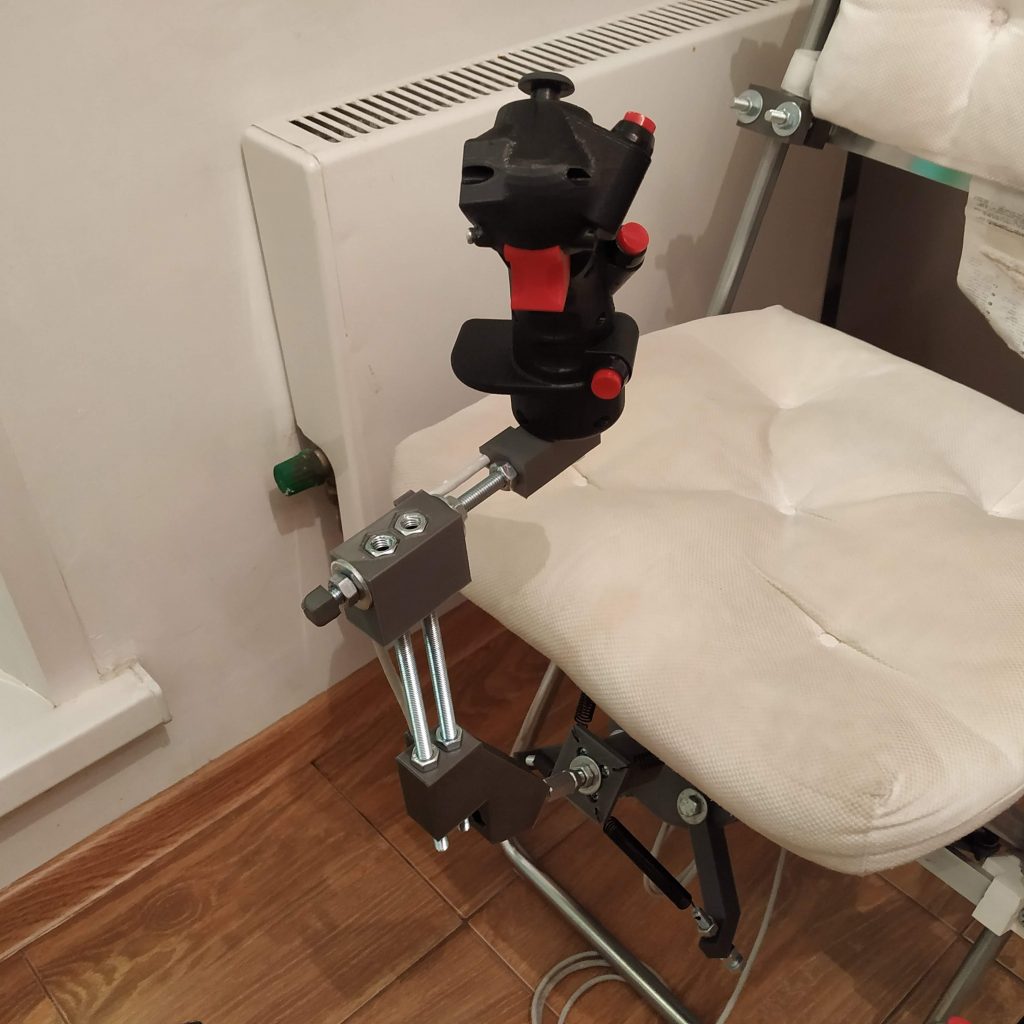
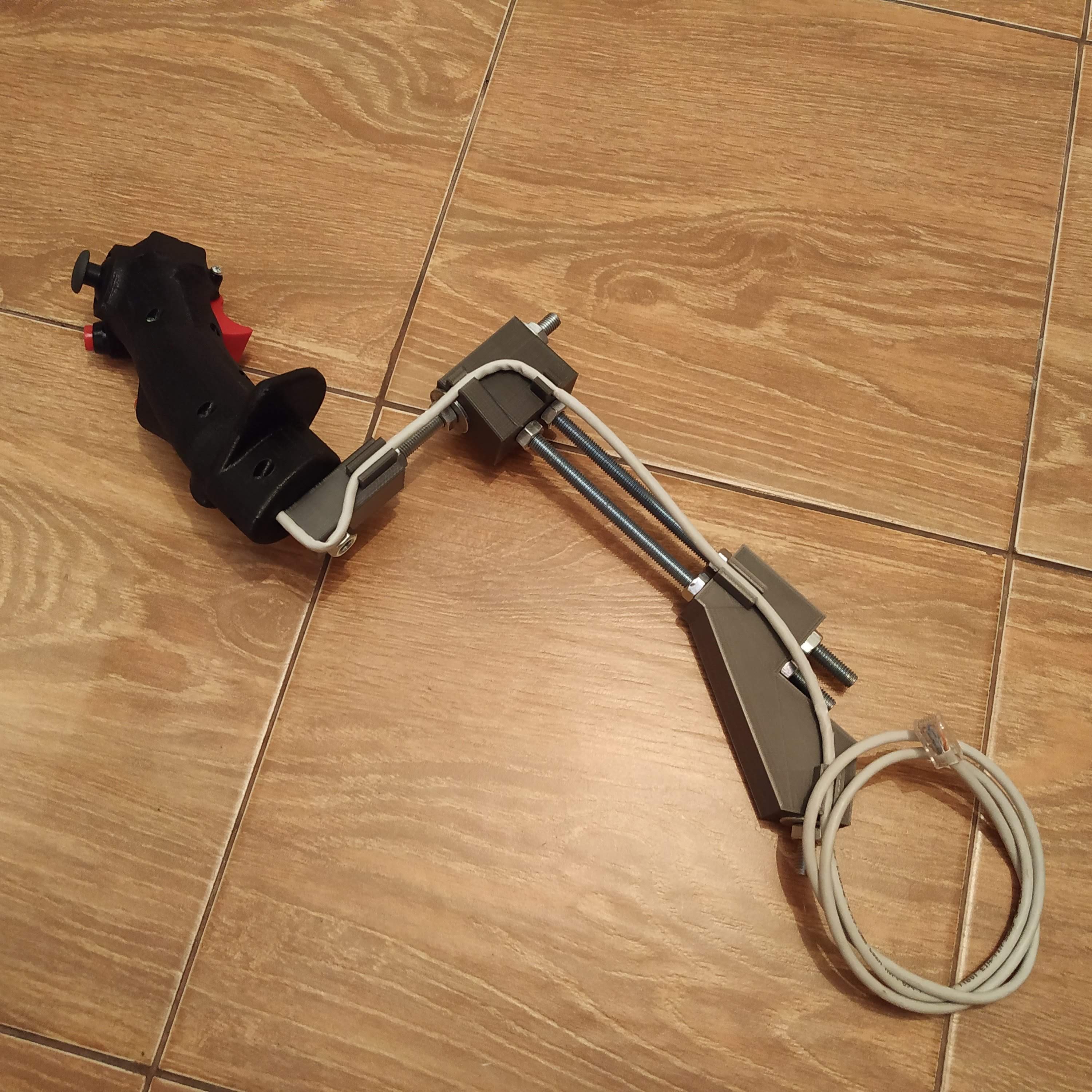
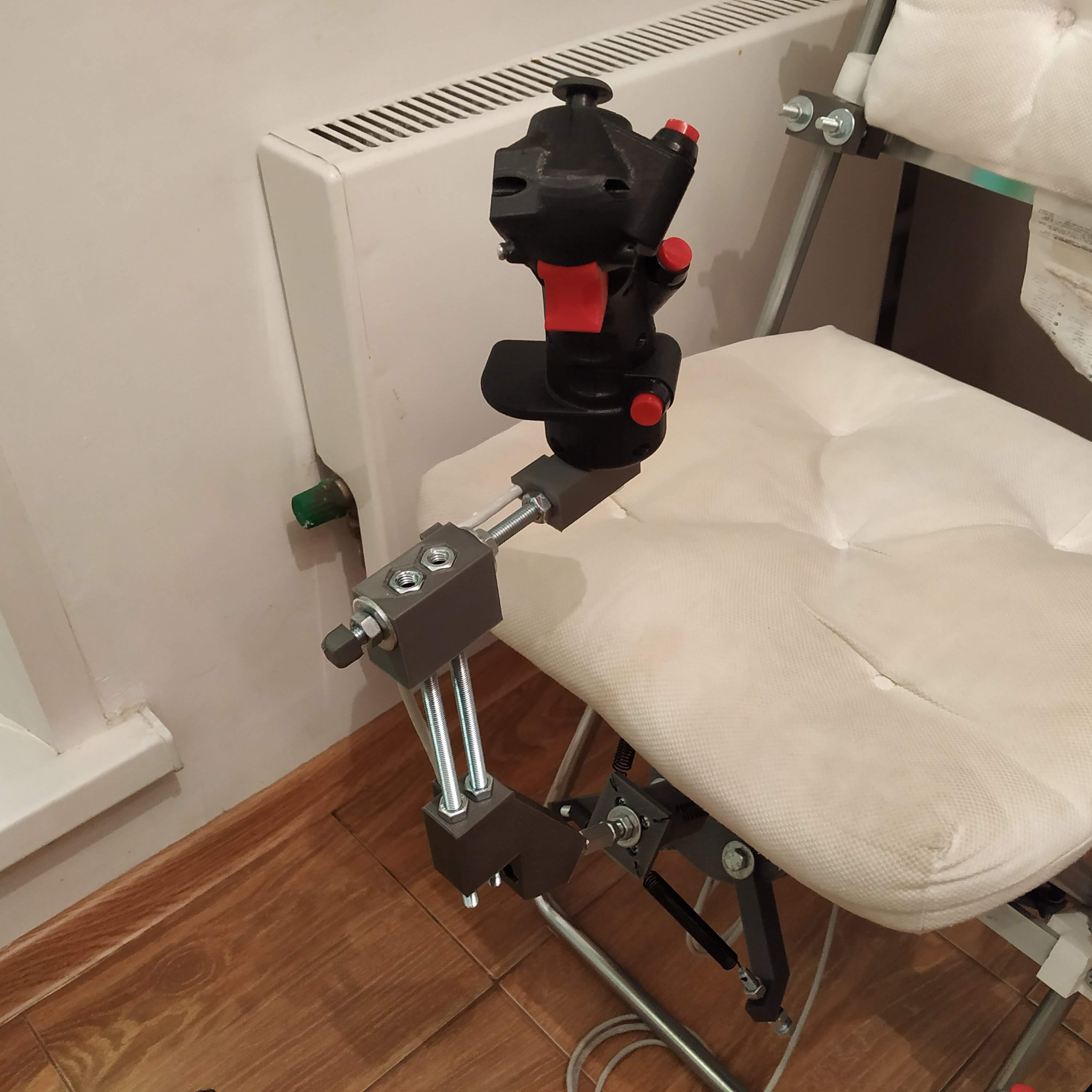
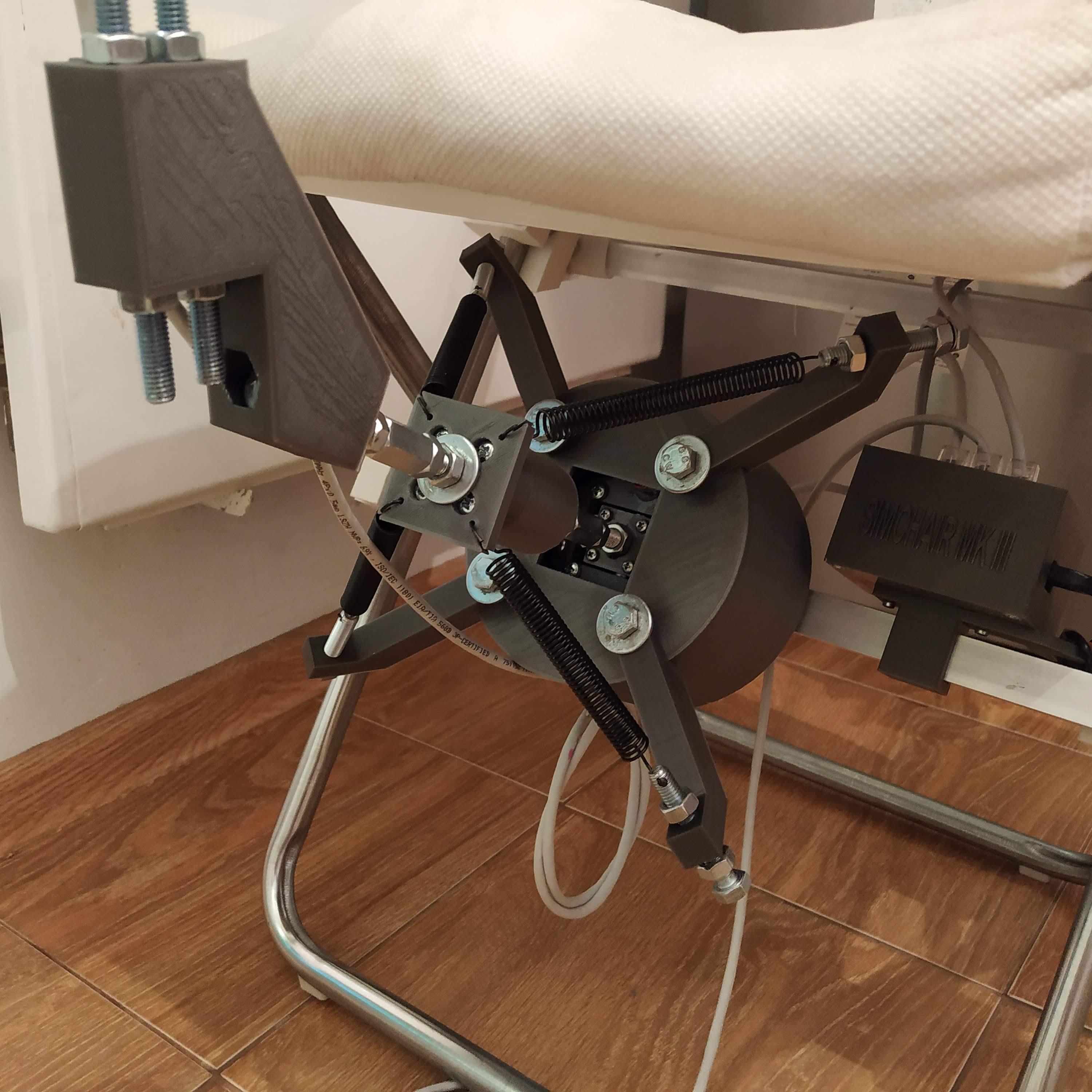
It is a cyclic gimbal, designed to simulate movements a pilot does in a real helicopter. A regular desktop joystick should be tilted to an angle around 40-45 degrees to reach its axis max or min value, while in a real heli you barely have to move the stick to fly, its more like applying pressure to the stick, and the nature of movements differs a bit when you have a long stick. This gimbal can be mounted to the frame under the IKEA GUNDE chair, in a way you won’t even notice it is there when you’re not flying. Detachable stick allows you to take it off quickly when you don’t need it, serving the same purpose. There’s
also an RJ45 socket for stick connection. Unlike the previous “light” version, this one provides stick centering with springs and more interesting and realistic software force trim system.

Components
1 * PLA plastic spool
4 * M8x105 bolts
1 * M8x55 bolts
3 * M8x30 bolts
5 * M8x75 bolts
1 * M8x60mm bolt
2 * M8 connector nut
1bag * M8 nuts
1 bag of M8 spring washers
1 bag of M8 reinforced washers
1 bag of regular M8 washers
18 * M4x35 screws and nuts
4 * M8x50mm screws
4 * M4x60mm screws
4 * M3x35mm screws
2 * SS495A Hall effect sensors
2 * 6x6x4mm or 5x5x5mm magnets
4 * ZZ608 skateboard bearings
ethernet cable
ribbon cable
glue gun with hot glue
TJ8P8C ethernet socket
1 * ADS1115 external I2C ADC module
1 * Simchair MKIII I2C controller
4*LADA2101 clutch pedal spring or similar (1,2mm thick, 11,5mm diameter, 53,7mm height without hooks, ~81mm with hooks when squeezed). Any similar spring with light to moderate tension should work. You can also order them from me in any quantity if you can’t find one at your place.
Available mods
- 5x5x5mm magnet holders
- quick-detach stick connector option
- simplified spring holders
Special features
- force trim support, different modes for spring-loaded and free stick
- sensitivity switching support (extreme precision mode)
Downloads
Assembly
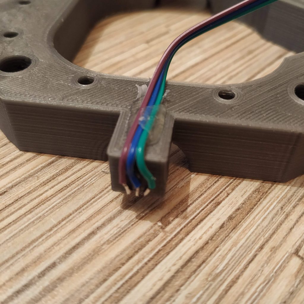
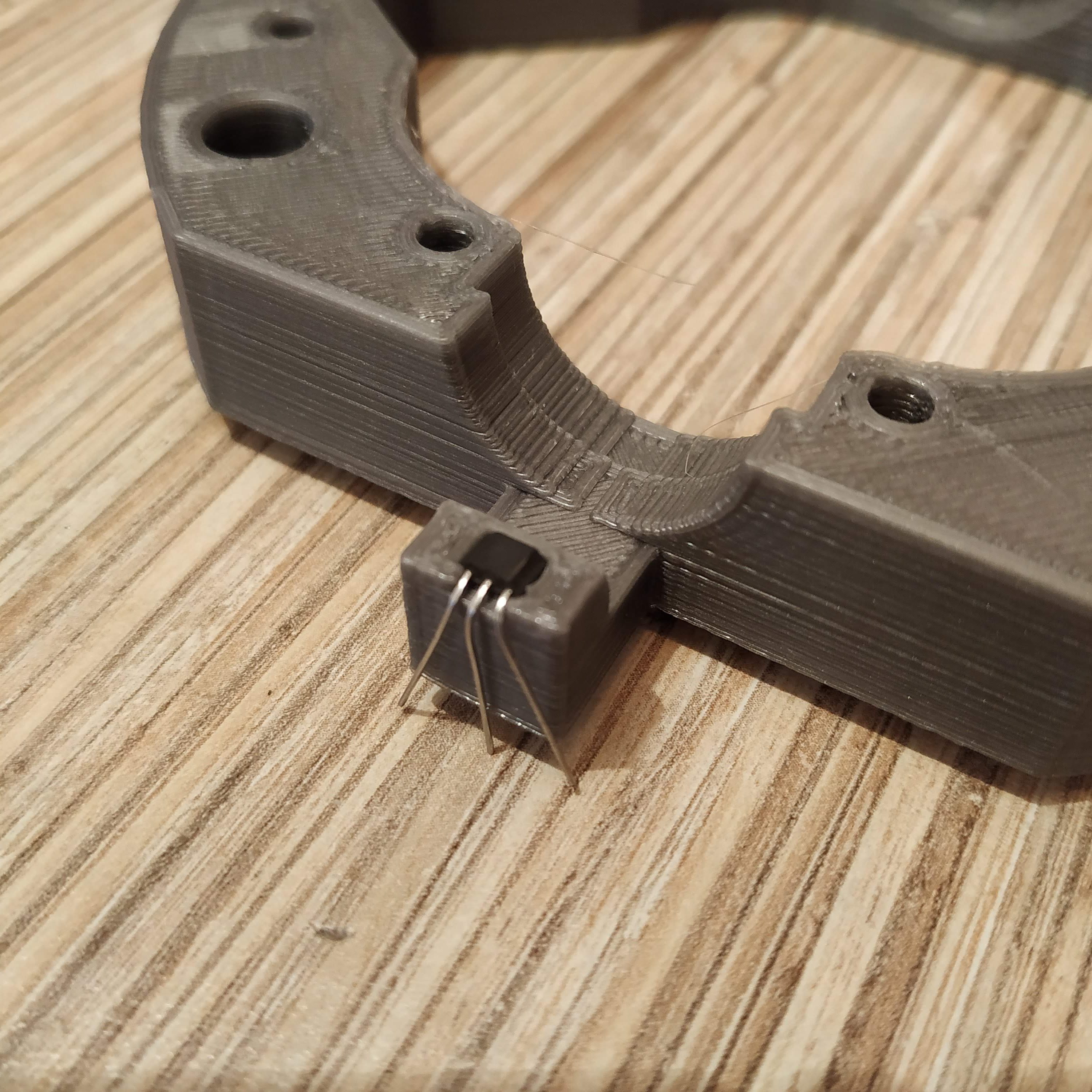
- Insert SS495A1 sensors into their sockets, secure them with a drop of superglue.
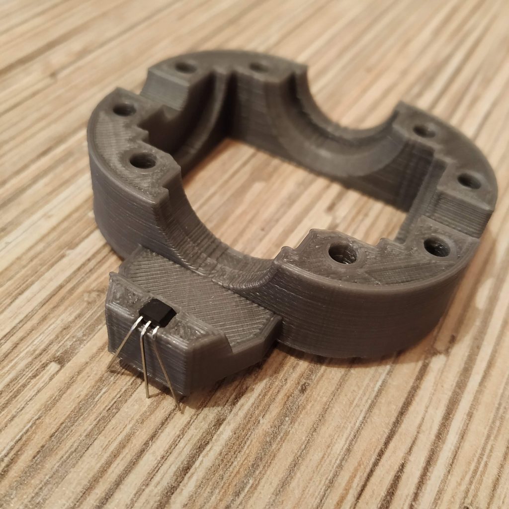

- Cut 2 3-wire cables off the ribbon, solder them to sensors, cut excess length of legs, secure cables with hot glue.
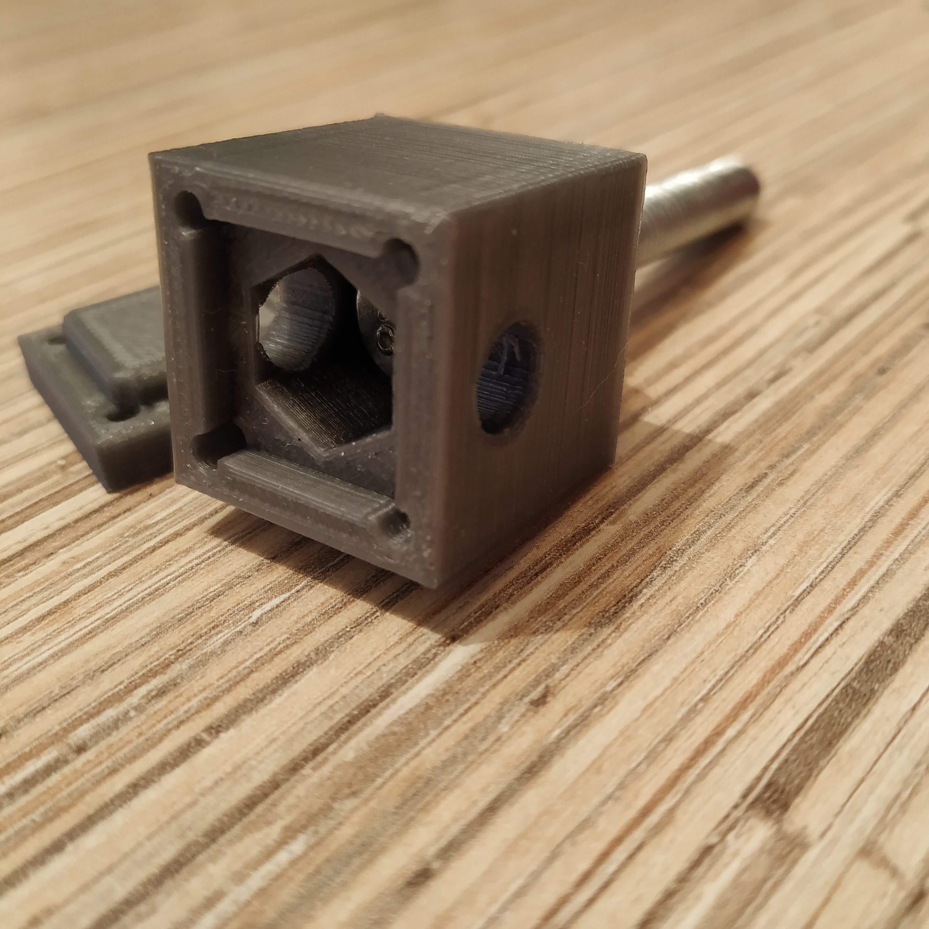
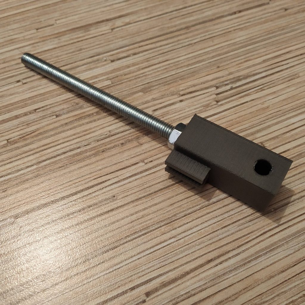
- Time to assemble the lever connector. Insert M8x60mm bolt into lever connector p1, add a washer and a nut, tighten firmly. Use a good drop of thread locker on the nut!

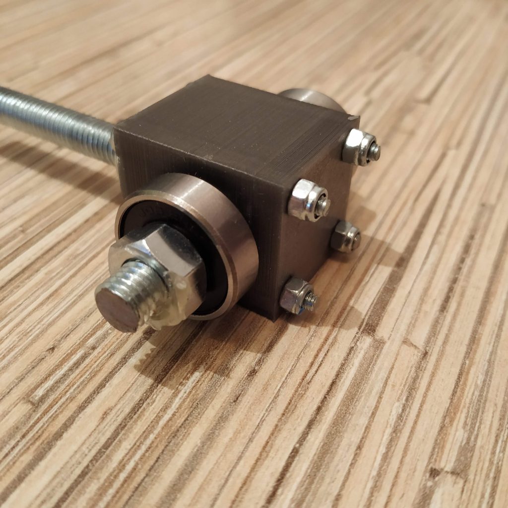
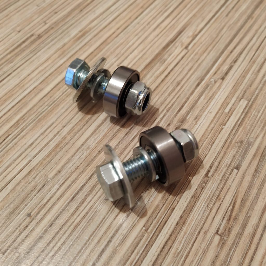
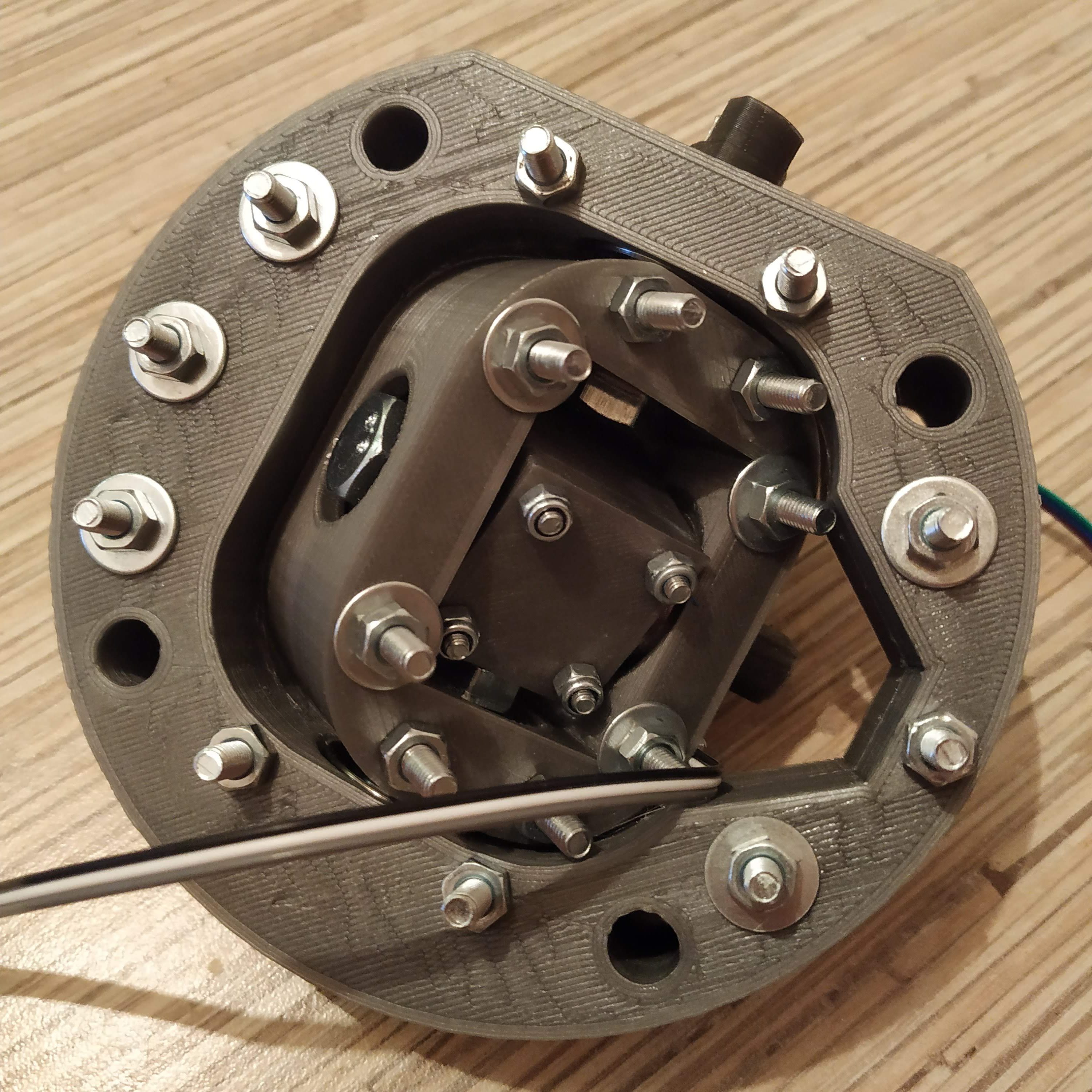
Put the bottom lid on. Insert M8x55mm bolt as shown on the picture below, put 2 bearings, 2 spring washers, and a nut onto it. Tighten firmly and check against the inner ring, loosen the nut a tiny bit if needed. There should be absolutely no backlash!
- After you have adjusted tension f the nut, secure it with a tiny drop of hot glue. Insert 4 M3*35mm bolts, put nyloc nuts onto them.
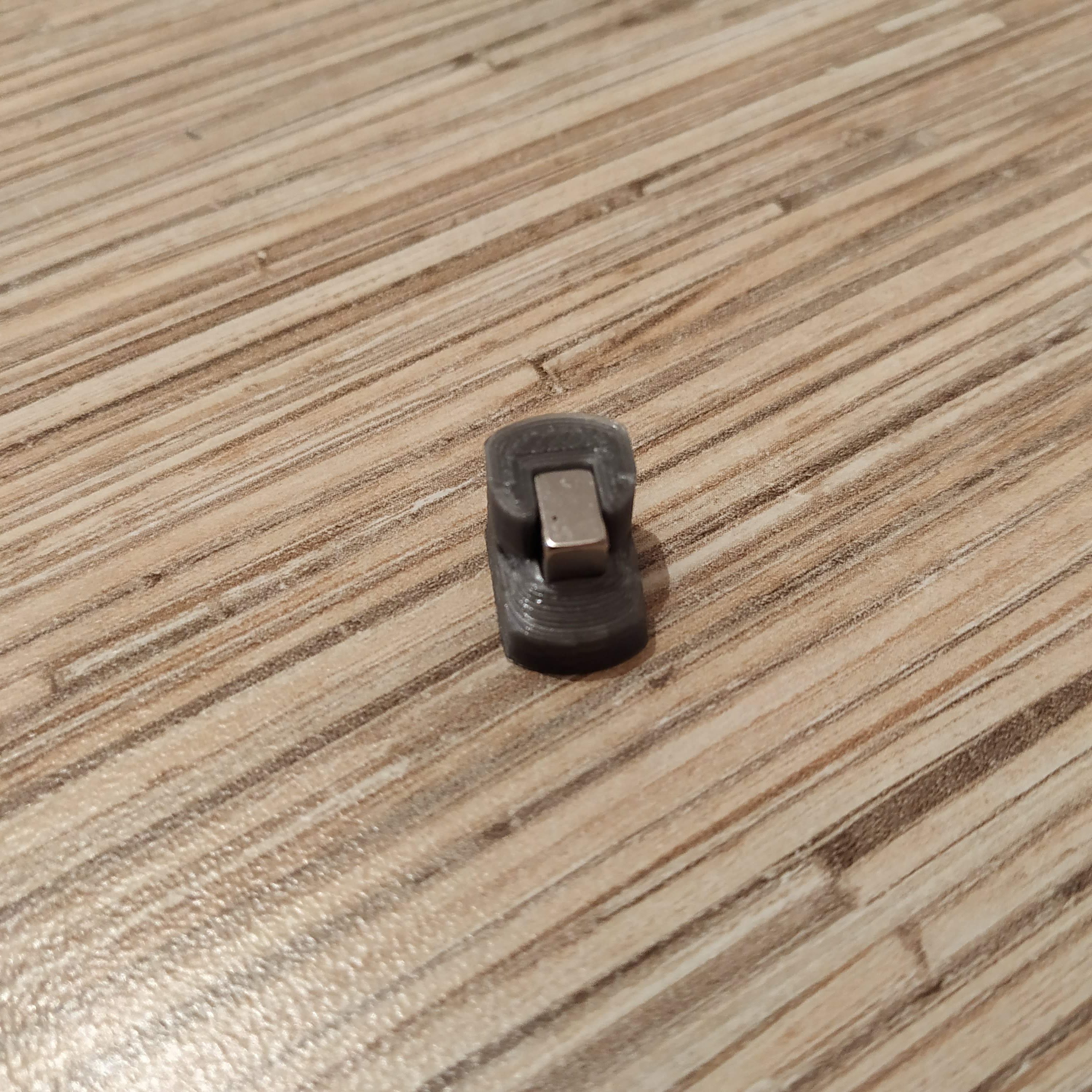
- Insert a magnet into a magnet holder. Put it onto the M8x55mm bolt of the lever connector assembly.

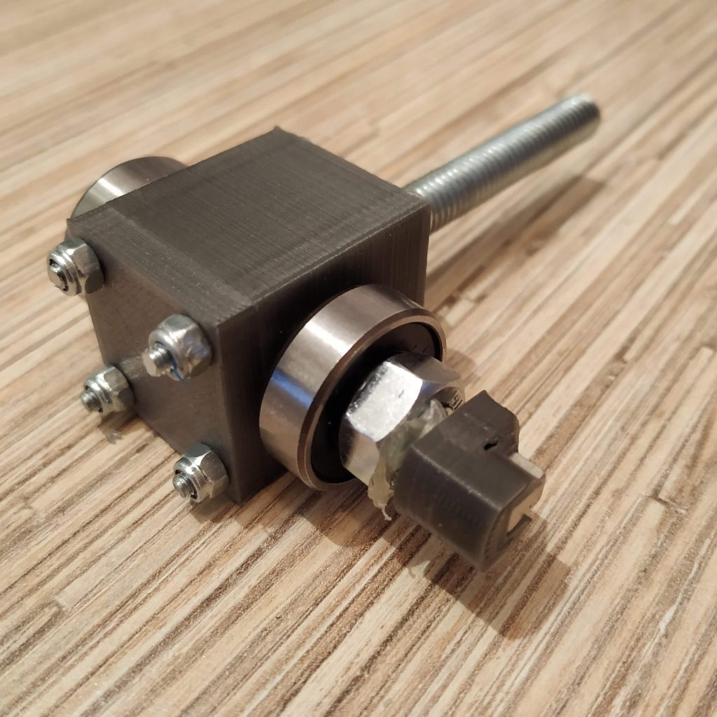
- Insert the lever connector assembly into the upper part of the inner ring. Make sure it fits tightly without backlash. Adjust if necessary.

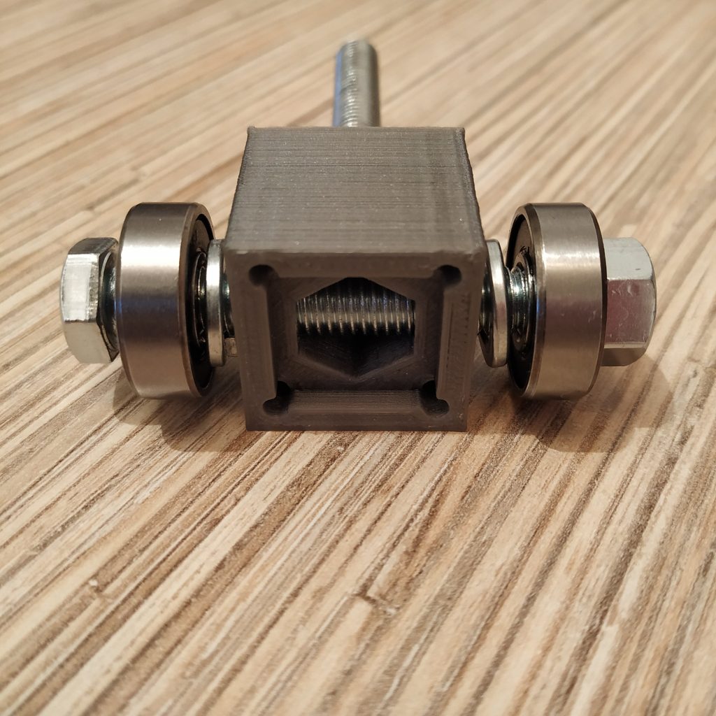
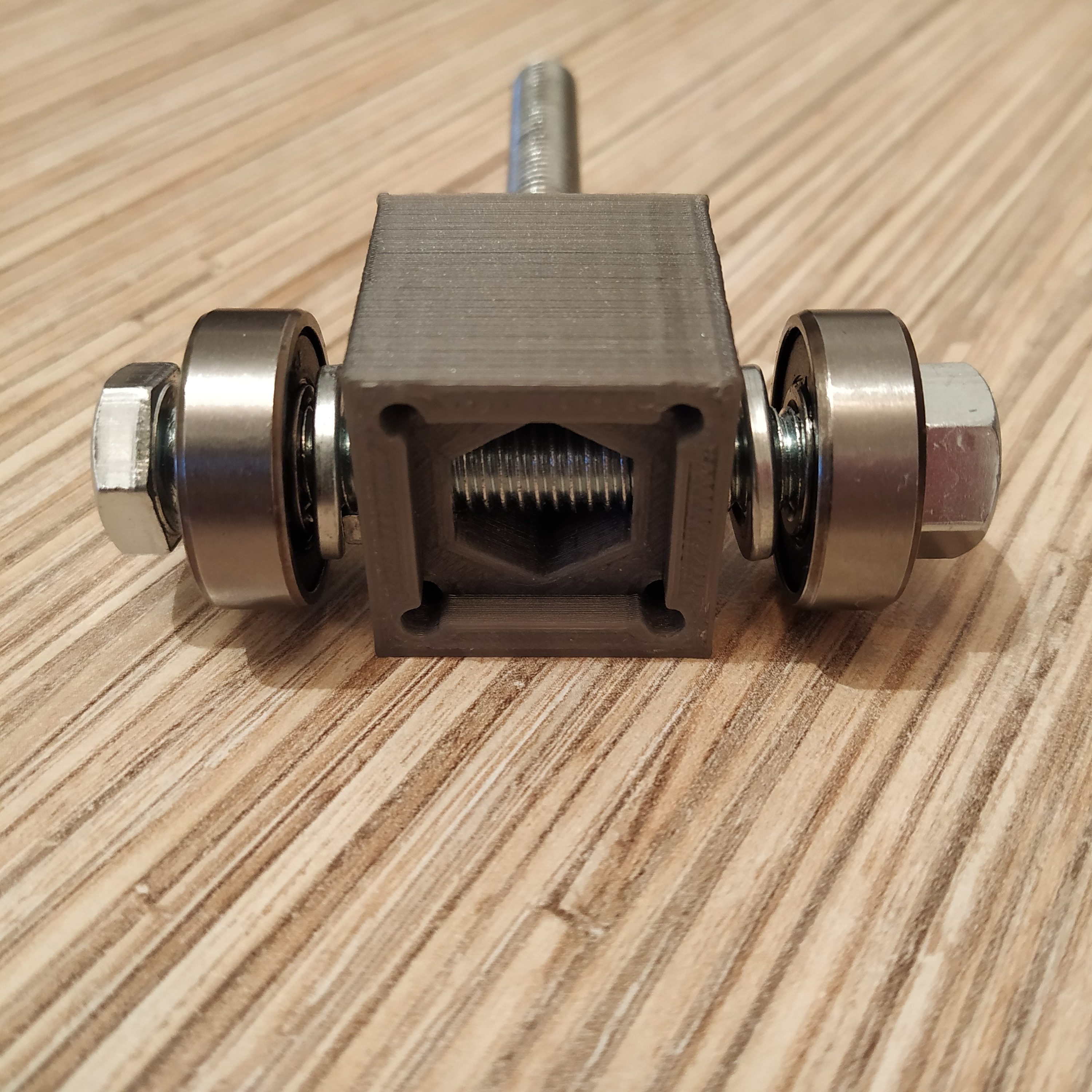
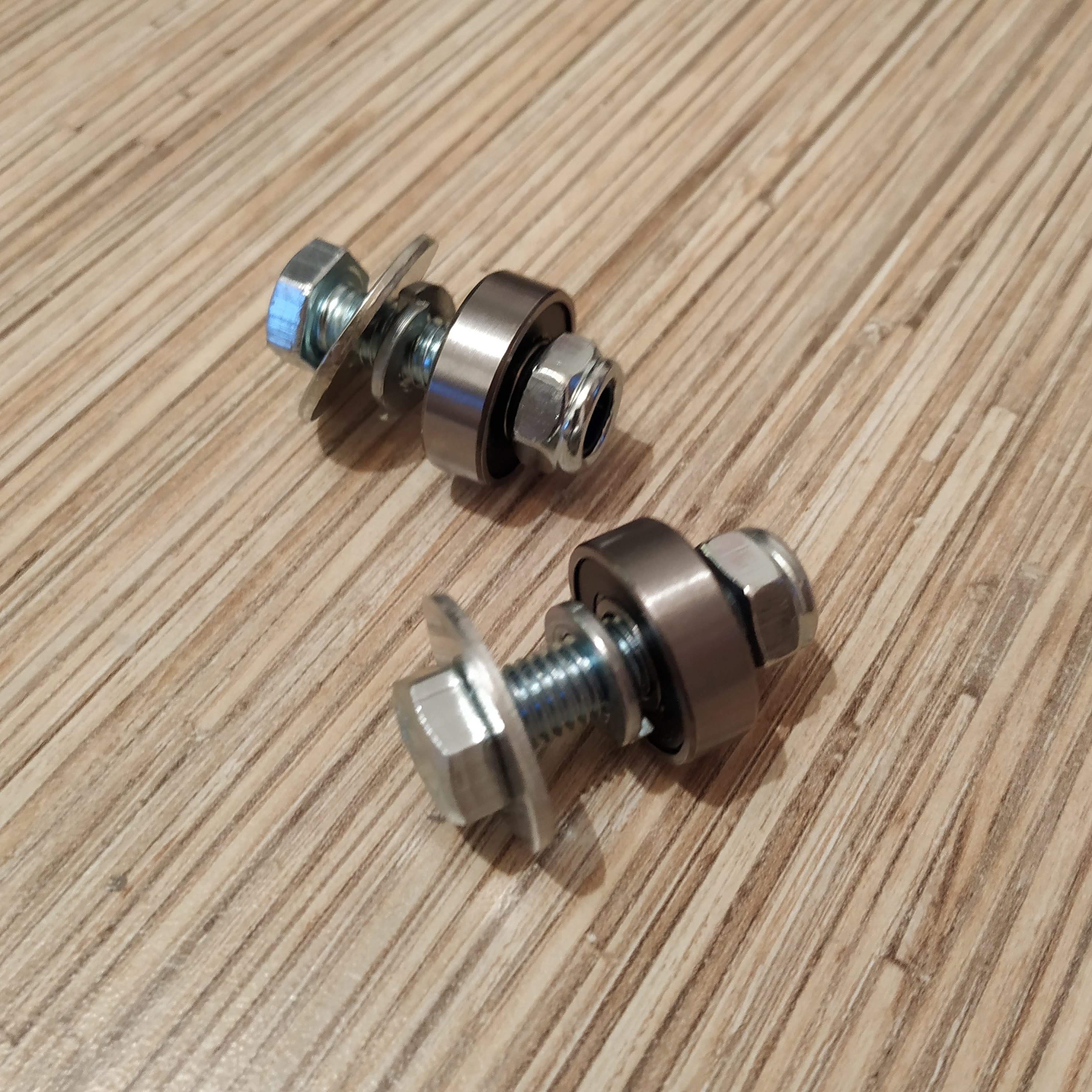
- Take 2 M8x30mm bolts. Put a reinforced M8 washer, a spring washer, a bearing, and a nut onto each of them (you can use a nyloc nut on the non-sensor side).
- Put these bolts into the inner ring upper half as shown on the picture below.
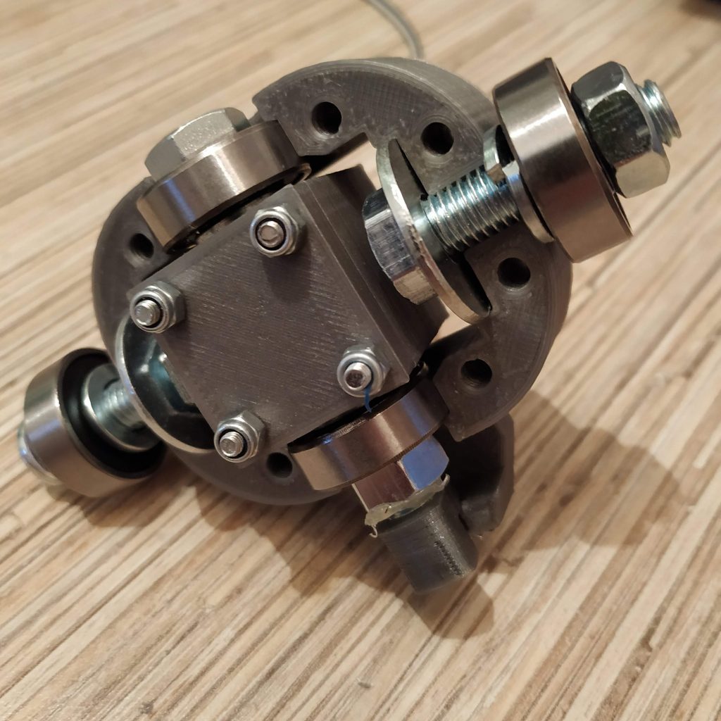
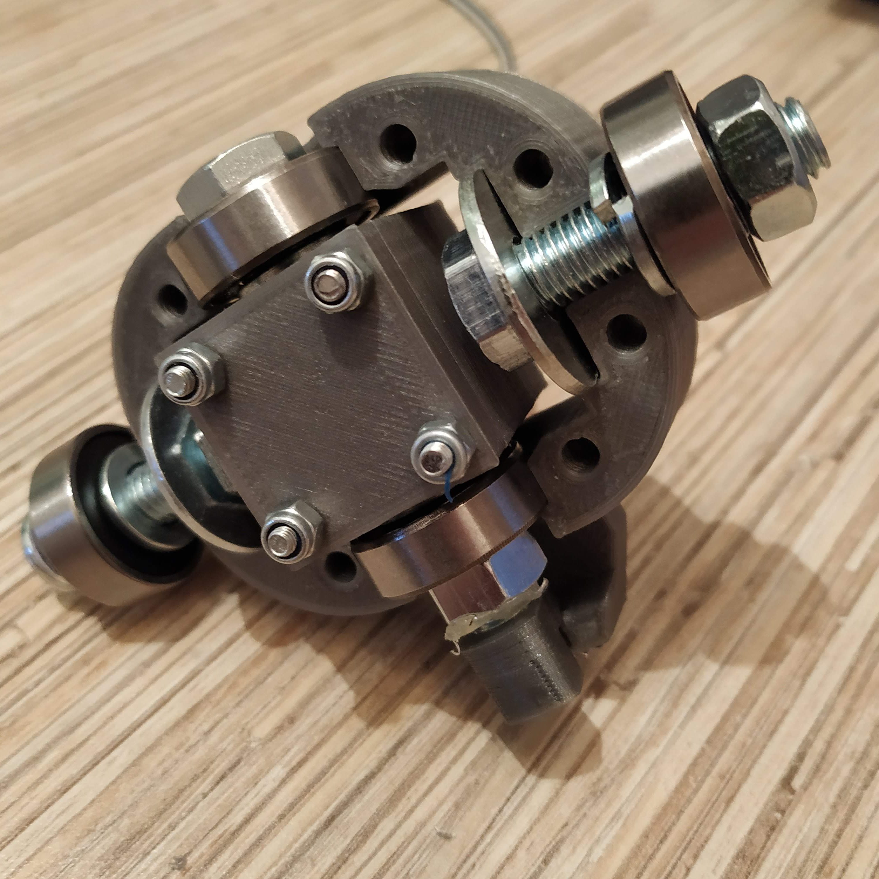
Add the lower part of the inner ring.
Insert 8 M4x35MM screws, put washers and nuts onto and tighten them firmly. Note that washers should not protrude beyond plastic part borders. Only use washers on 4 innermost screws.
- Tighten Y axis nuts. Make sure the magnet holder rotates freely! Adjust its position if necessary.
- Fix the X axis sensor cable onto the inner ring with hot glue.
- Insert Y axis magnet into its holder, and attach it to the Y axis bolt.

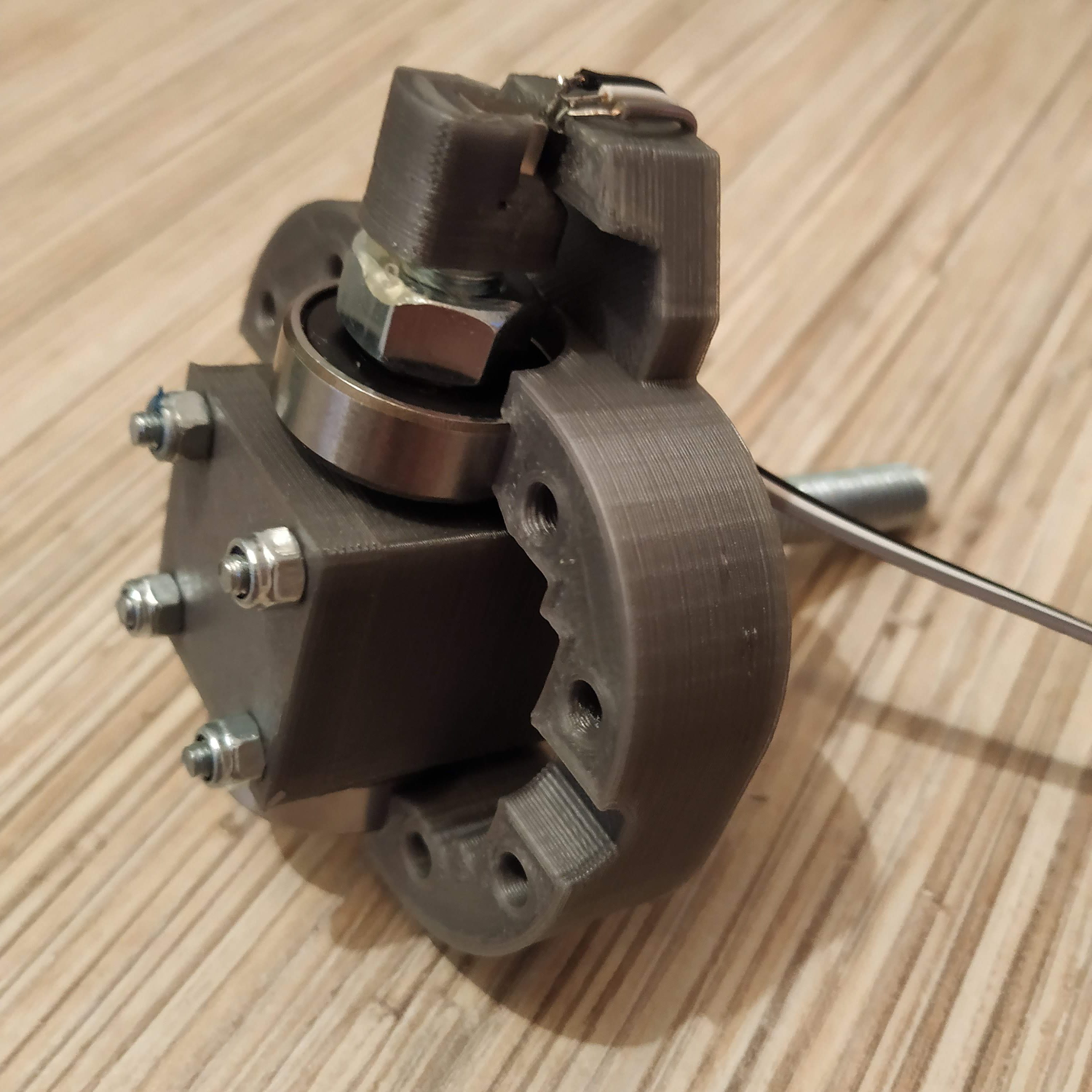
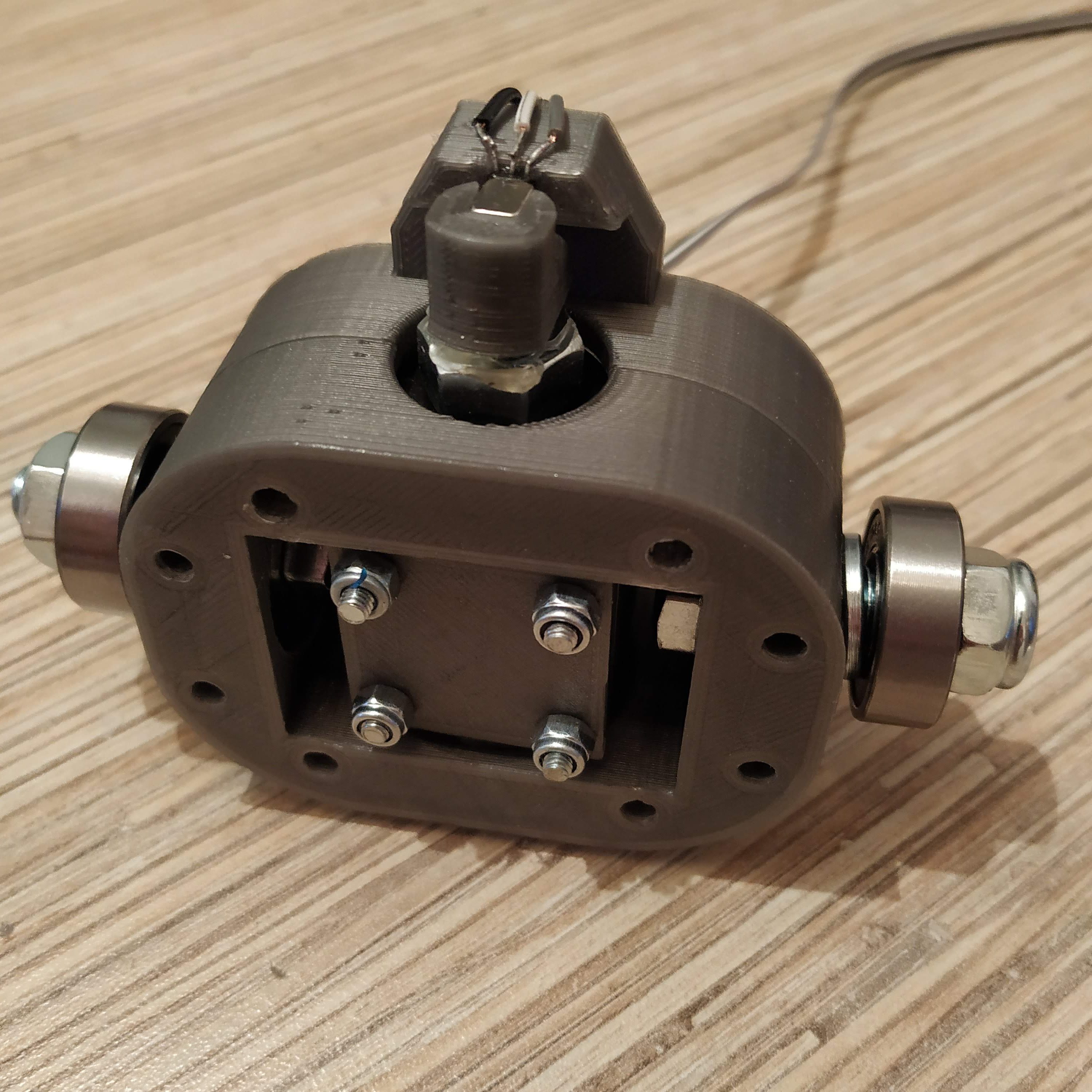
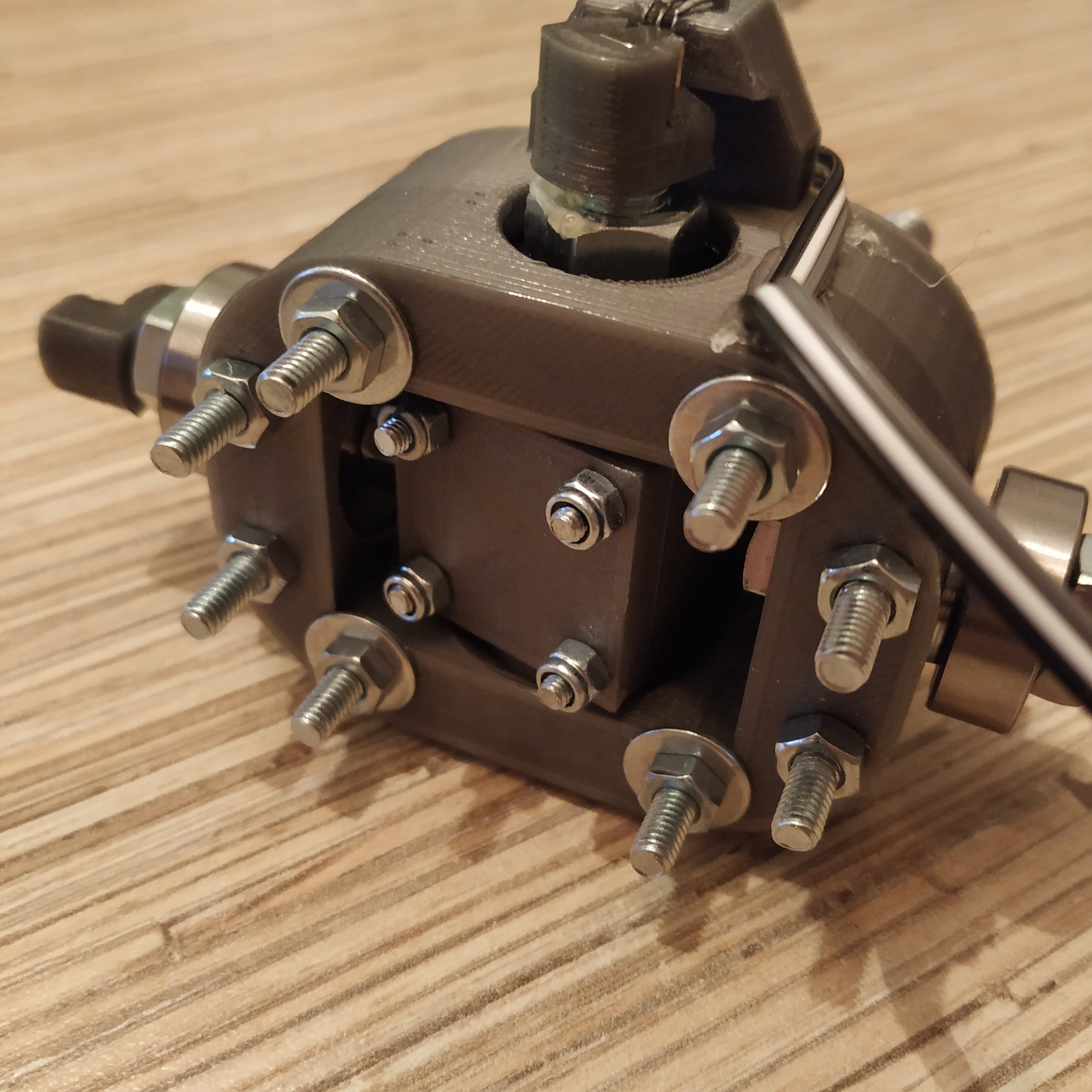
- Insert the inner ring assembly into the outer ring. Check for absence of backlash! Fix 2 halves of the outer ring with 10 M4x35mm screws, washers and nuts. Make sure Y axis magnet holder rotates freely. Adjust its position if necessary.

- Secure Y axis cable on a side of the outer ring with some hot glue.
- Now, it’s time to calibrate the gimbal. Solder the header to an ADS1115 board. Solder 4 wire cable cut from a ribbon to 1st 4 pins of an ethernet socket. Connect everything as follows:
SS495A X AXIS SIGNAL -> ADC A0
SS495A Y AXIS SIGNAL -> ADC A1
SS495A VCCs -> ADS1115 VCC -> TJ8P8C PIN 1 -> ETHERNET CABLE WHITE-ORANGE WIRE
SS495A GNDs -> ADS1115 GND -> TJ8P8C PIN 2 -> ETHERNET CABLE ORANGE WIRE
ADS1115 SCL -> ETHERNET CABLE WHITE-GREEN WIRE -> TJ8P8C PIN 3
ADS1115 SDA -> ETHERNET CABLE BLUE WIRE -> TJ8P8C PIN 4
- Center the gimbal. Uncomment following lines in c_flight_stick_gimbal.ino:
// uncomment next 3 lines for cyclic calibration
// Serial.print(x);
// Serial.print(” “);
// Serial.println(y);
Reflash the master controller, open serial port monitor, rotate magnets until you will see values close to 16384.

After final adjustment, center the gimbal again and make sure values are still close to 16384. As a final check, comment out “Serial.print” lines in master controller sketch again, reflash the master controller, and check the stick is centered in joy.cpl. Cyclic gimbal registers as X and Y axes of the 1st Arduino Leonardo joystick in the list. Do not worry if values will be slightly off, force trim feature will fix that.
- Fix magnet holders in-place with a drop of hot glue. Do not touch them with a nozzle of a glue gun!
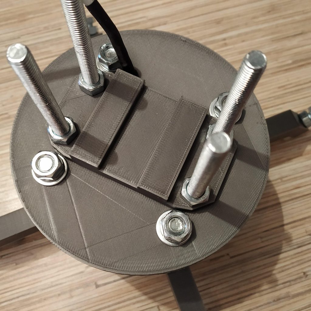
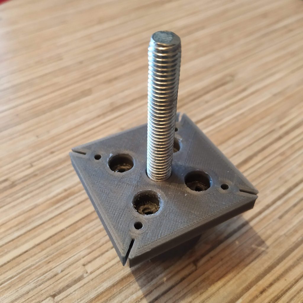
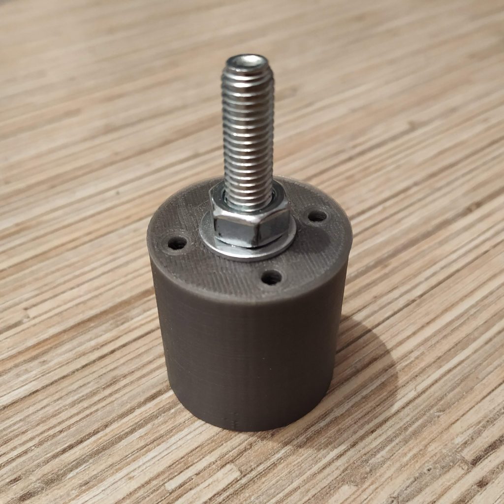
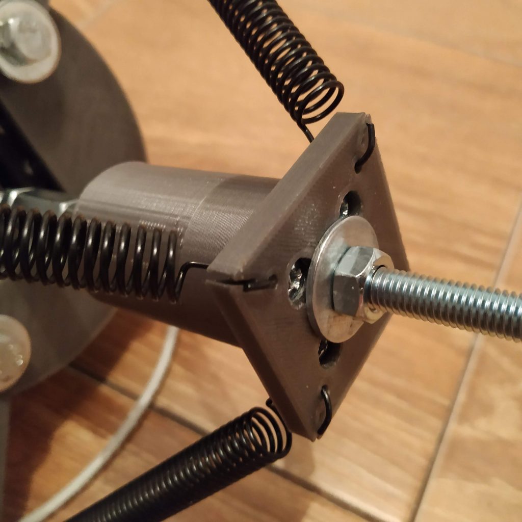
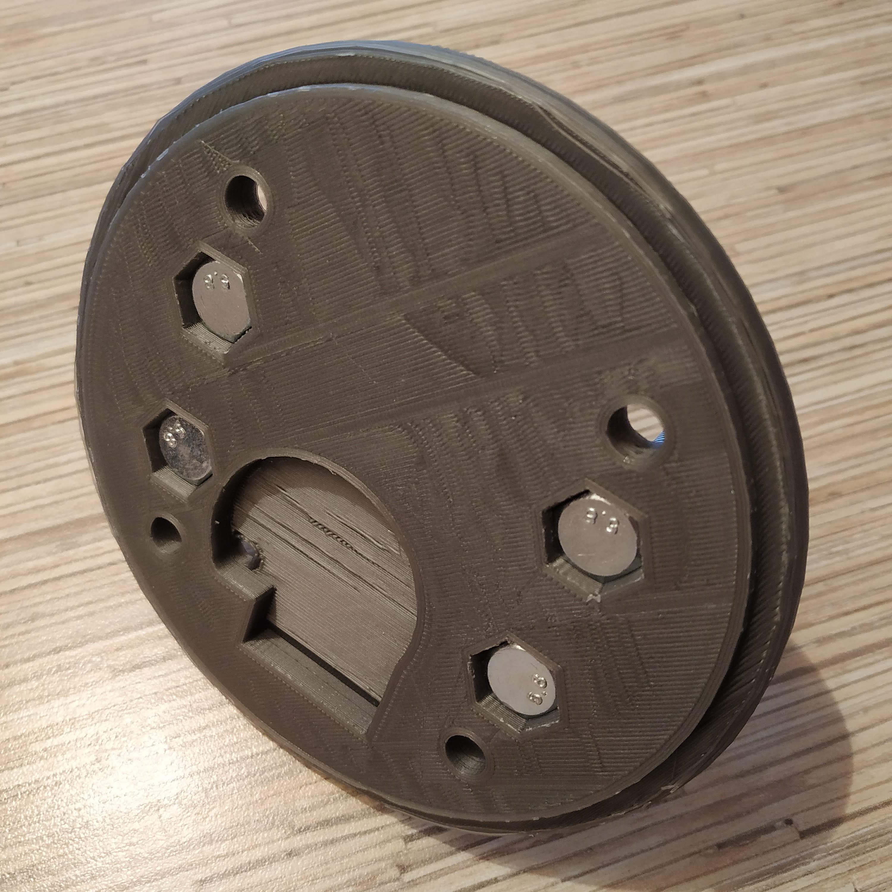
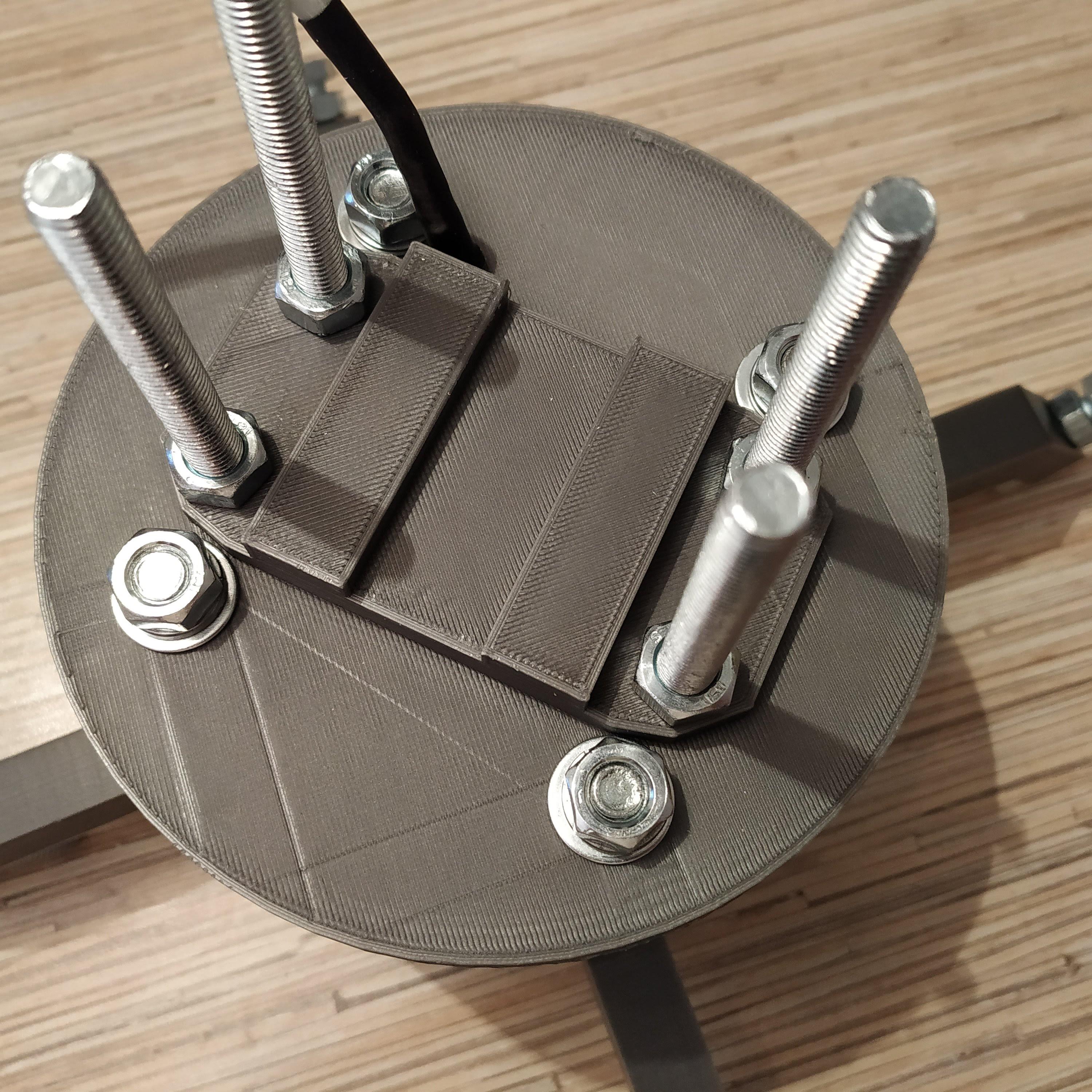
- Insert 4 M8x75mm bolts into the housing lid. Put nuts onto bolts and tighten firmly.
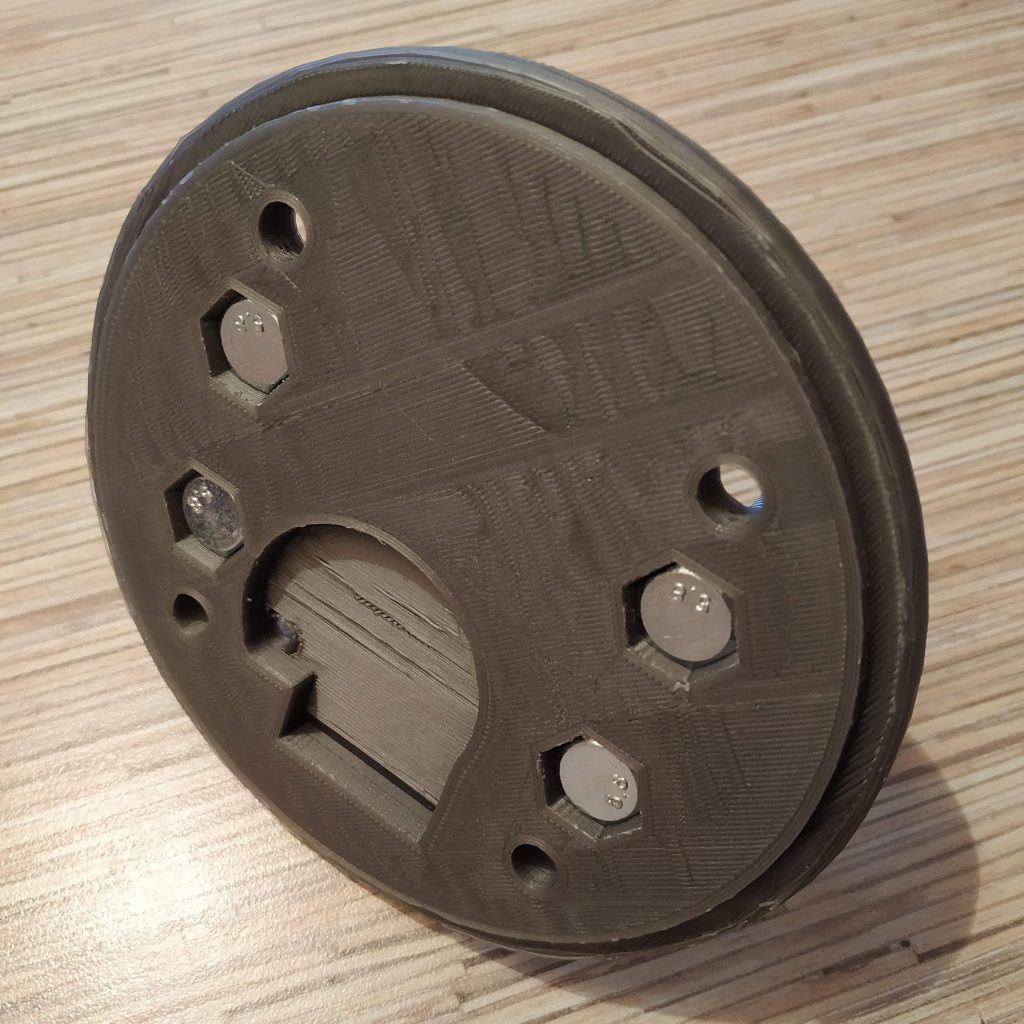
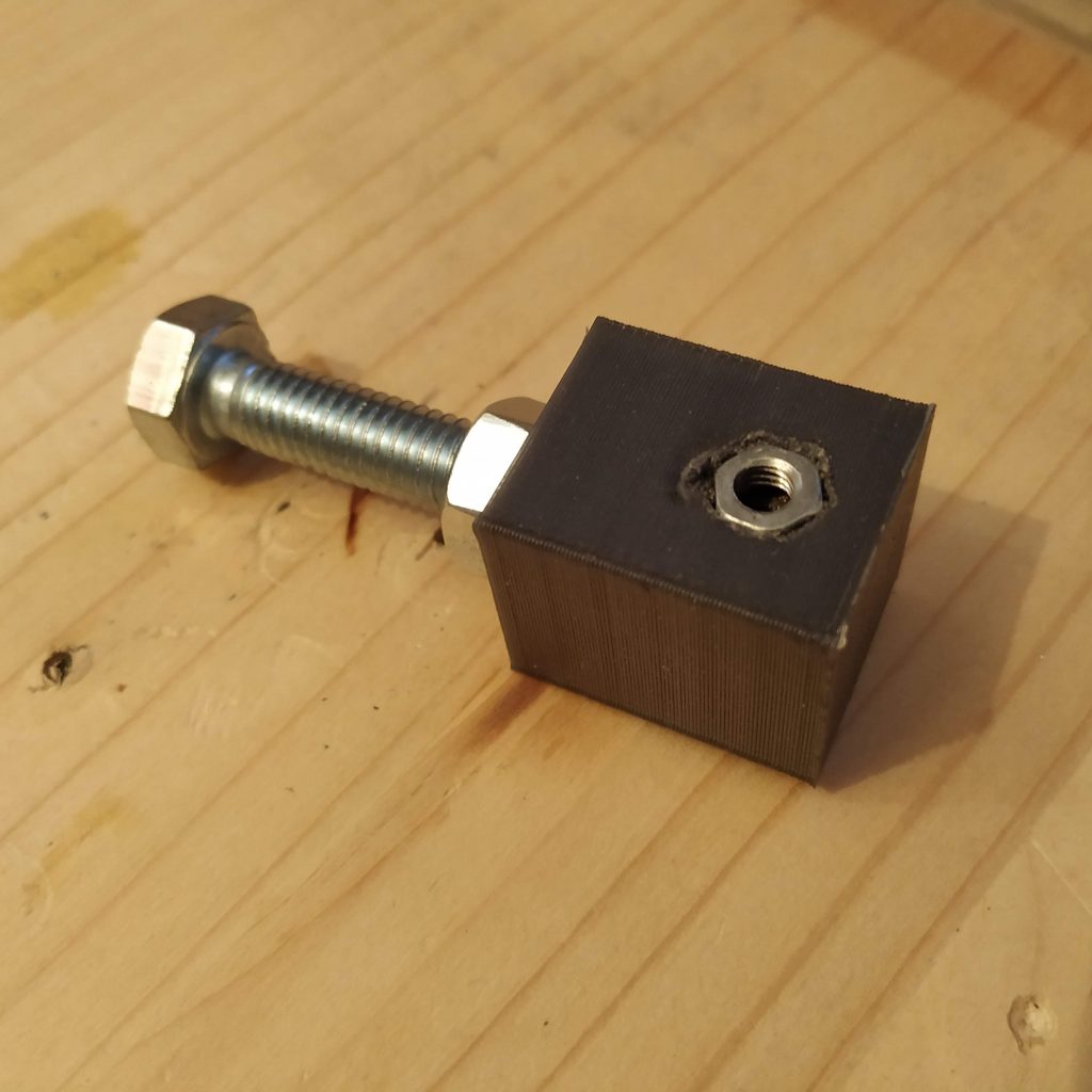
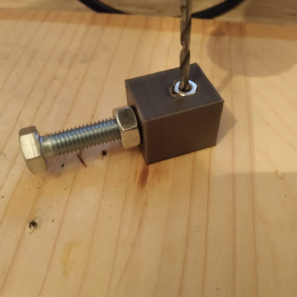
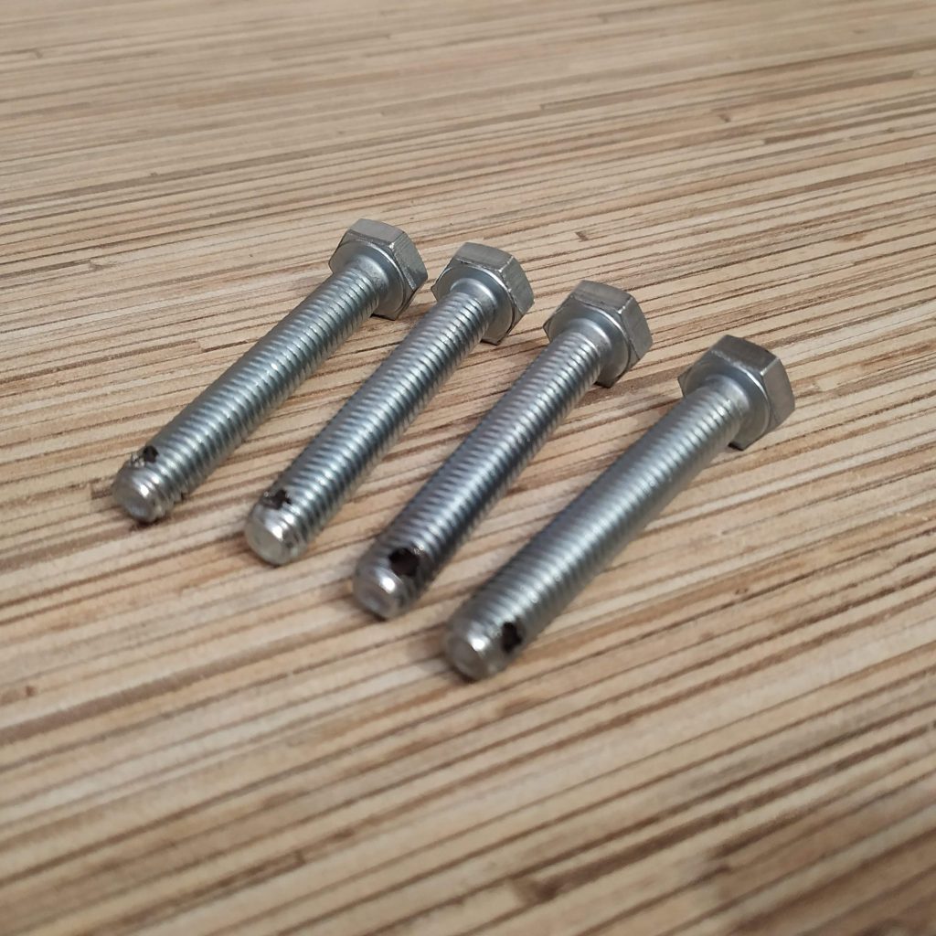
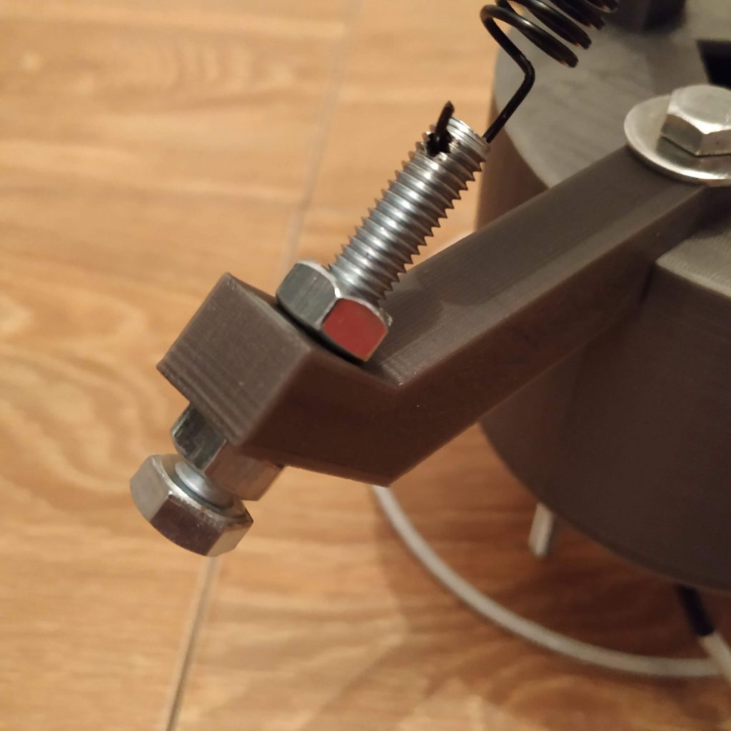
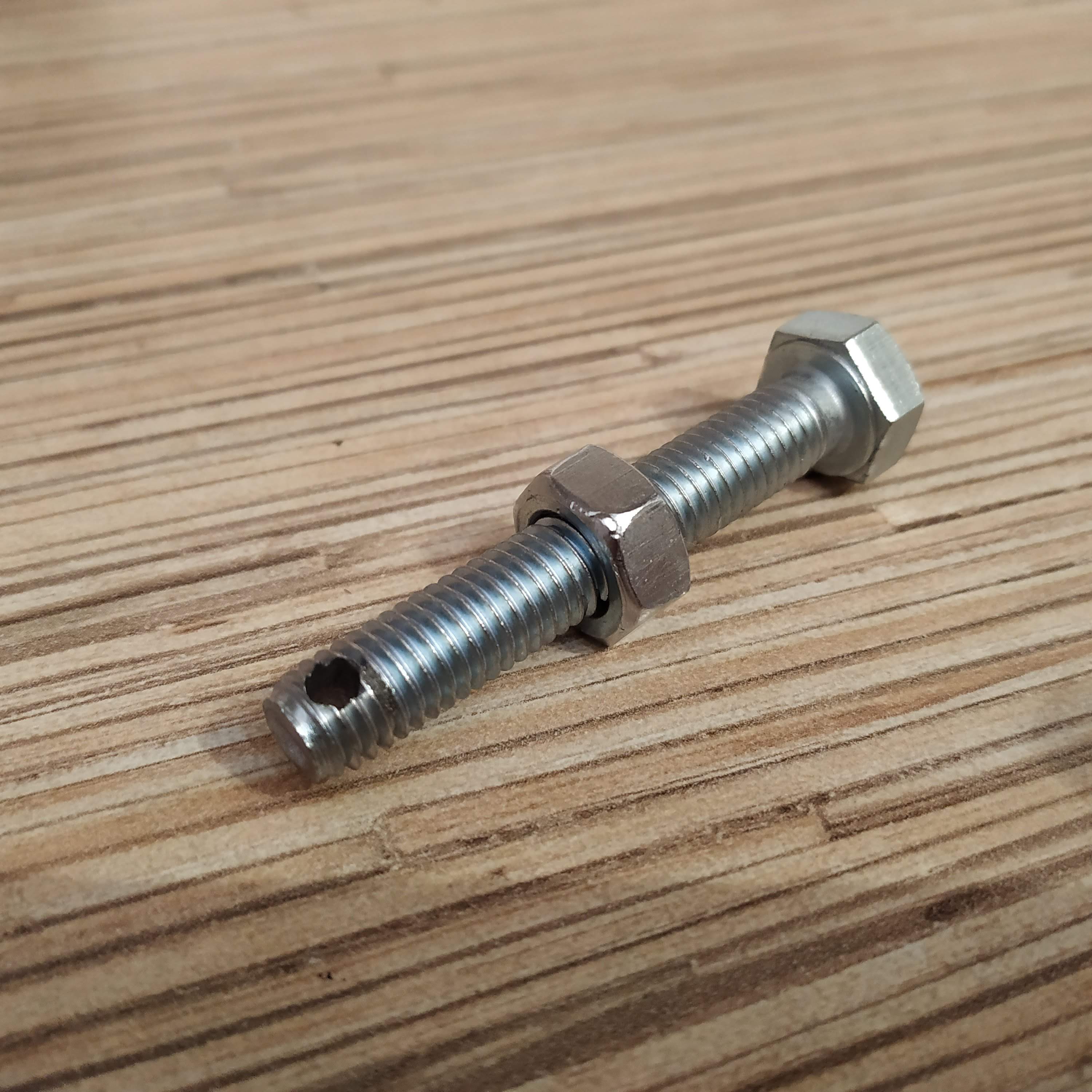
- Using provided drill guide tool, drill holes in 4 M8x50mm bolts. To do that, insert an M4 nut into its socket in the tool. Spill some cold water inside of the guide. Drill holes carefully, do not leat the drill guide to overheat, cool the bolt with cold water if needed. Do not press on the drill too hard. Change the M4 nut if needed. You may need more than 1 guide tool to drill all 4 bolts. After drilling each bolt, polish outer edges of a hole by unscrewing & screwing a nut over it for a few times.

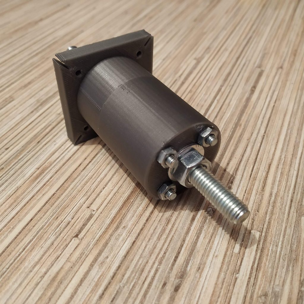
- Put a nut onto each bolt, then screw them into spring holder parts. Add one more nut onto each bolt. Do not tighten nuts yet.

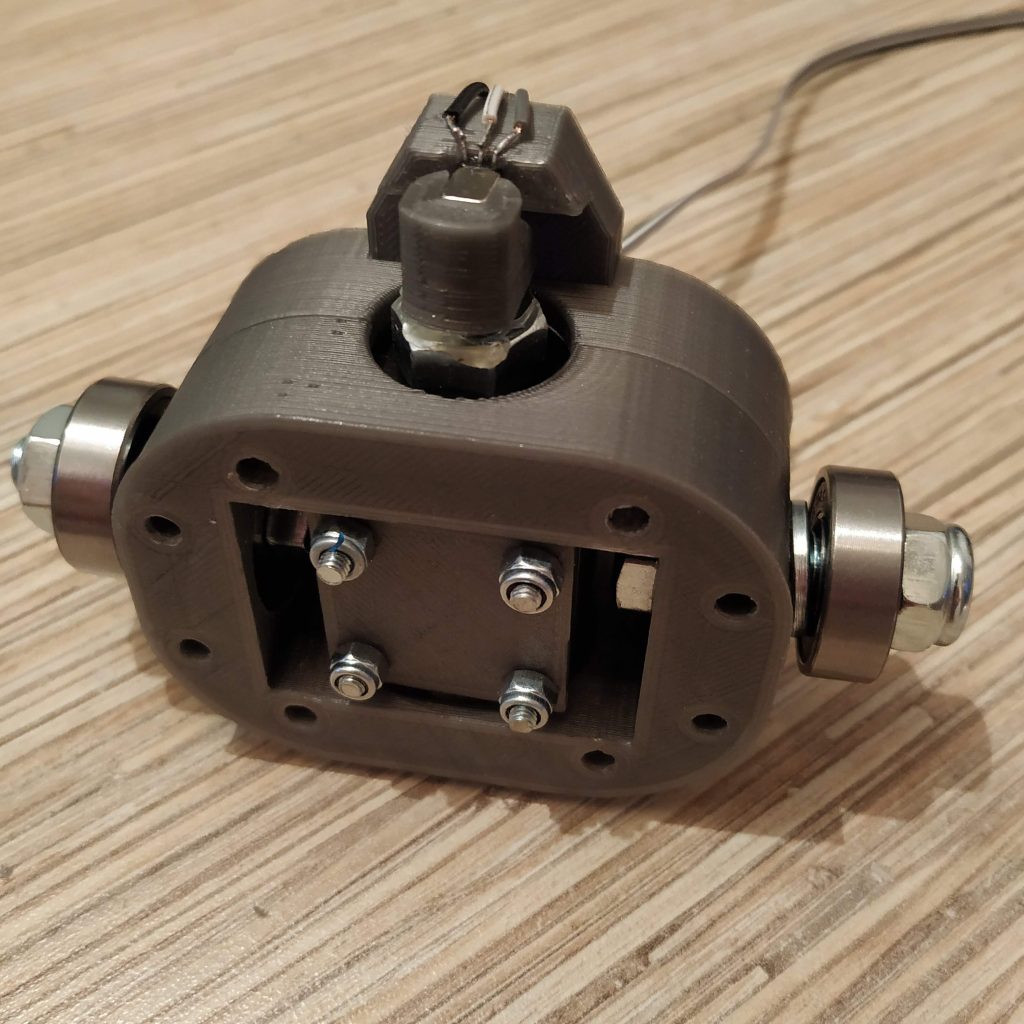
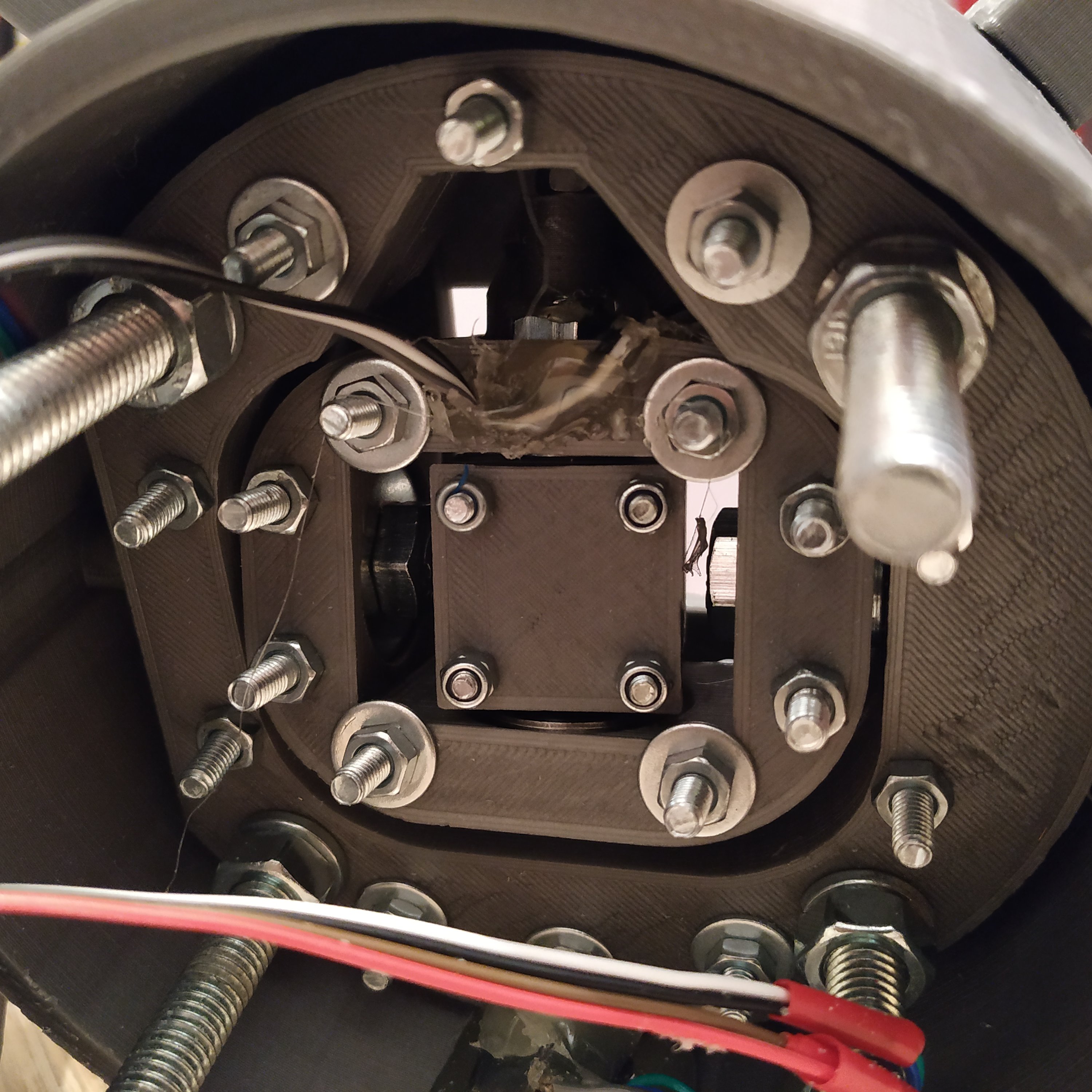
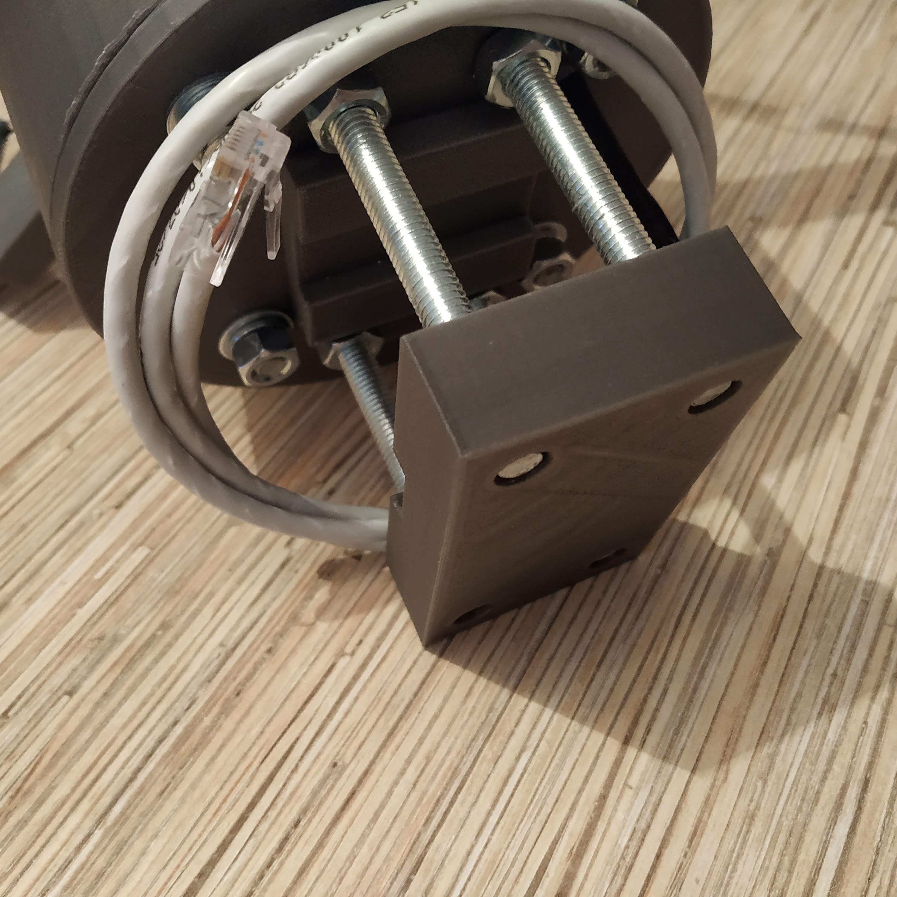
- Put the gimbal assembly into its housing. An Ethernet socket should be on the bottom. Put 4 M8x105mm bolts through reinforced washers, spring holders, gimbal housing and a gimbal. Put spring washers and nuts onto bolts from the inner side of the housing.If upgrading from earlier version with non-adjustable tensioners, only change bolt at a time.
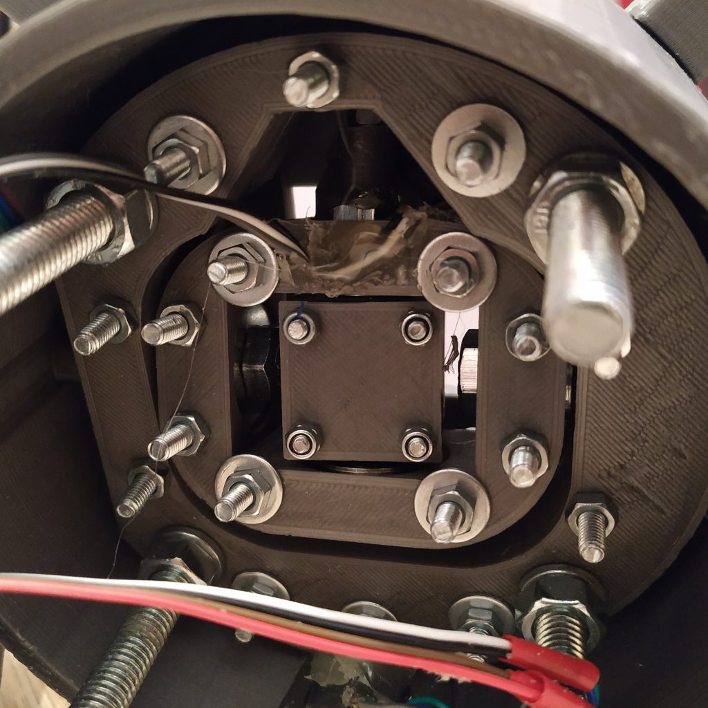
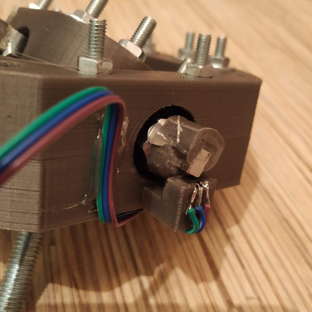
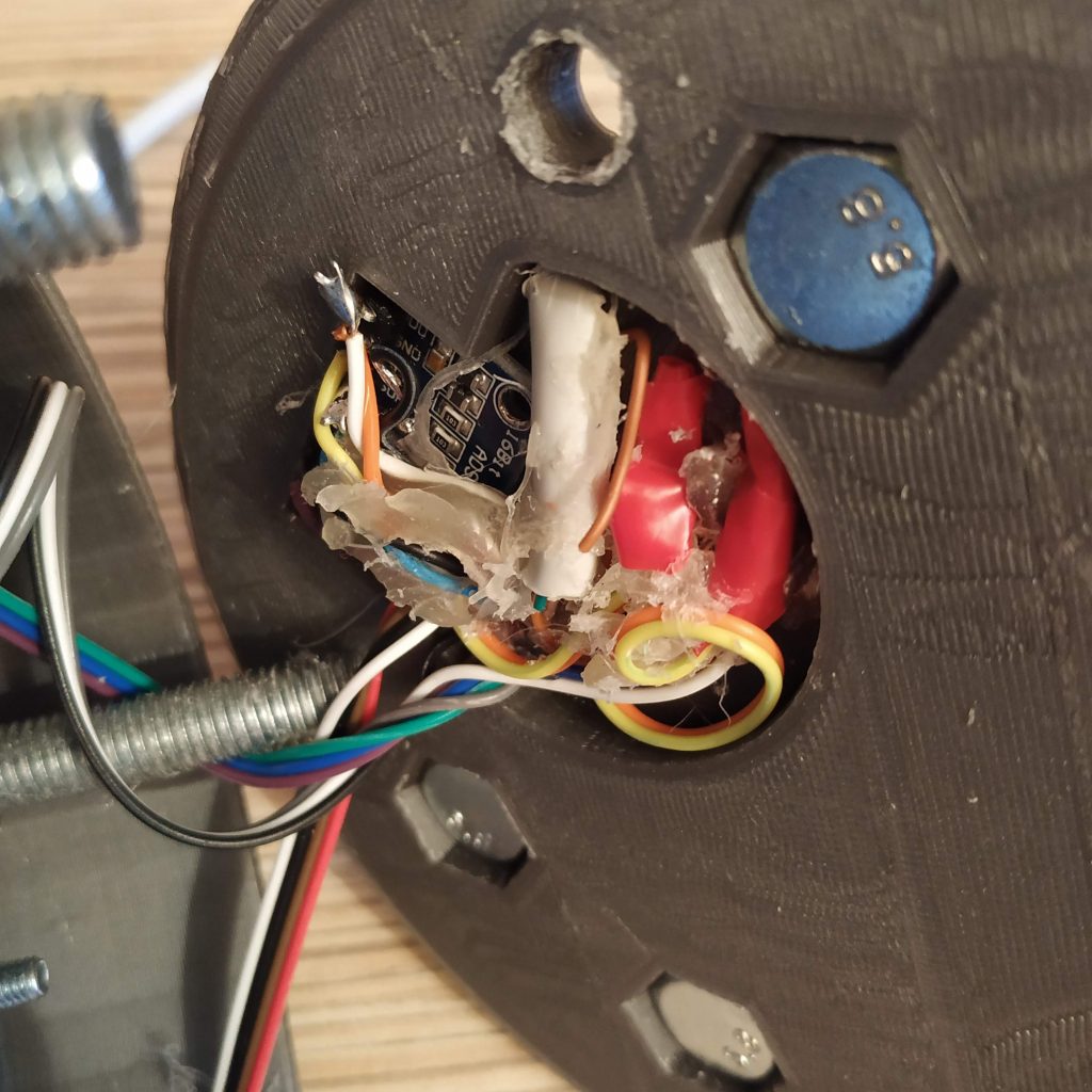
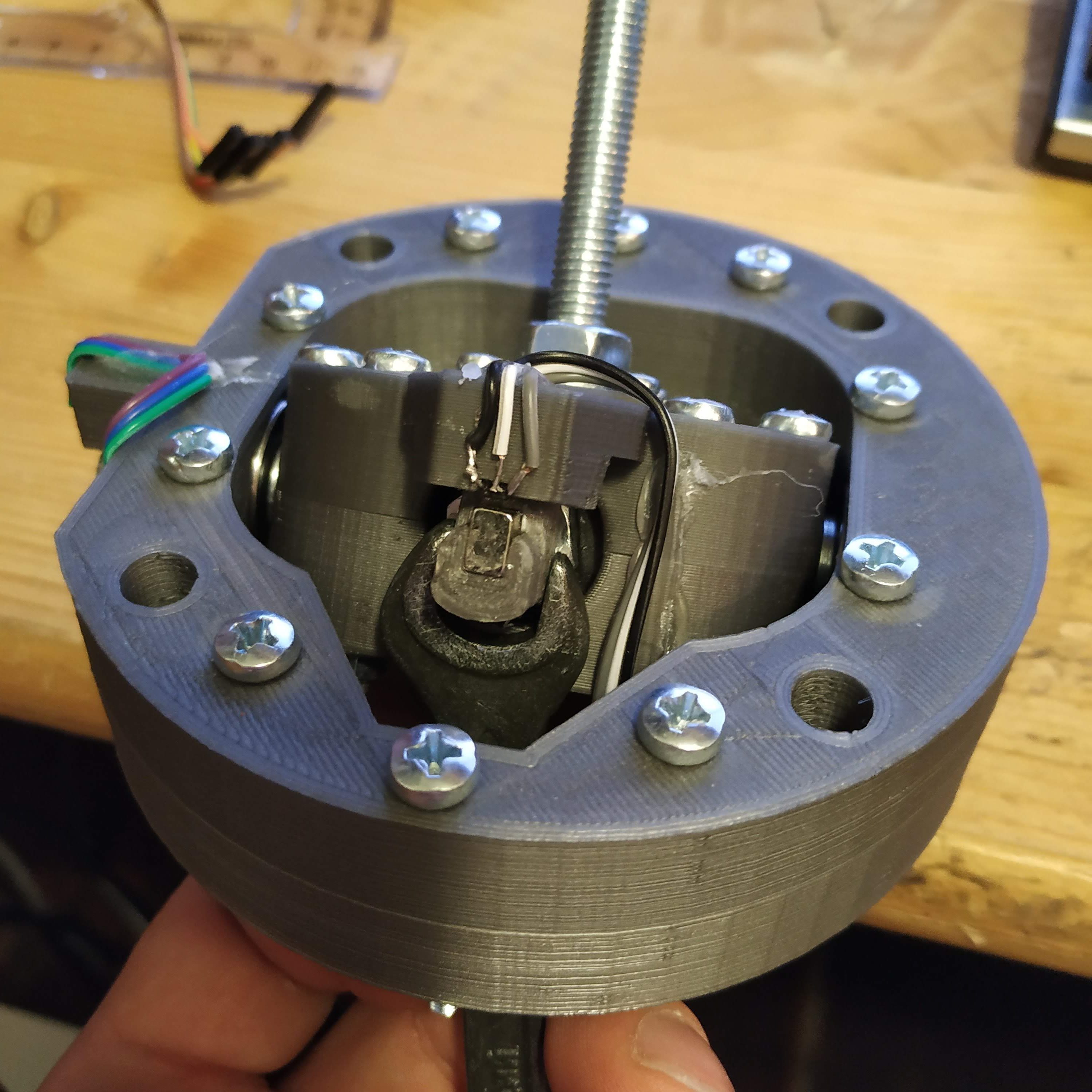
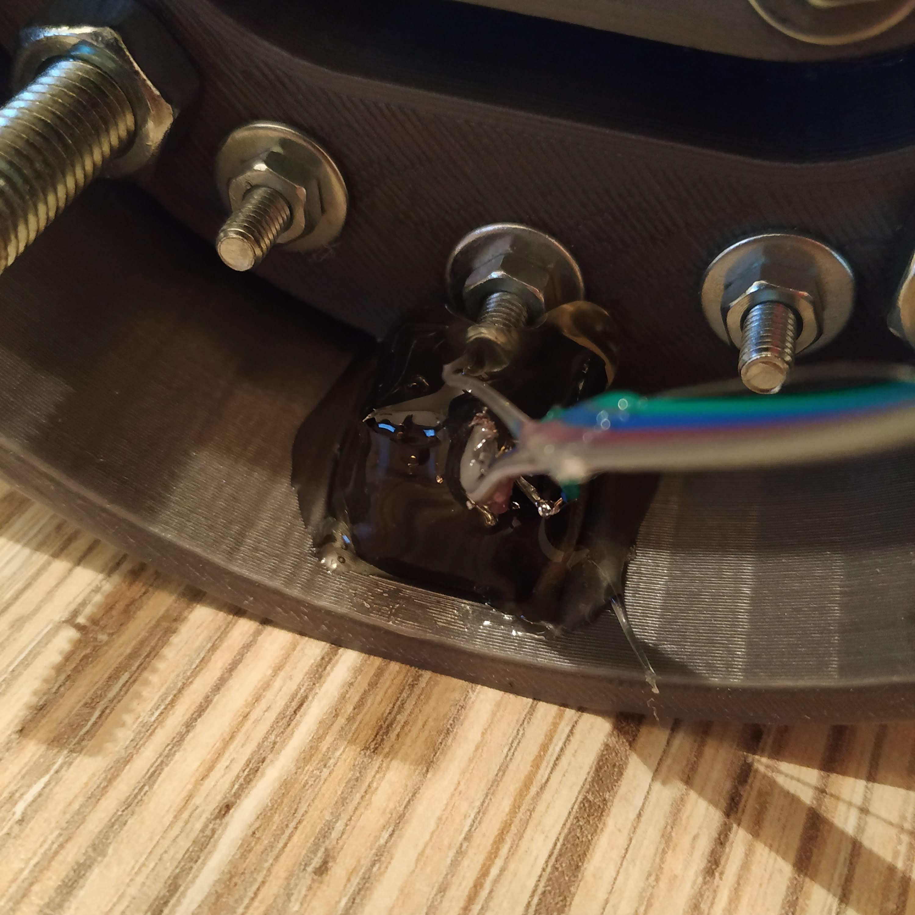
- Cut a dent in a center of the upper edge of the ethernet socket, enough for it to clear the screw. Insert the socket into its slot. Cut excess pins, bend soldered pins into different directions, as shown on the photo. Use a bit of hot glue to fix the socket in place.

- Put an ethernet cable through the lid. Bend pins of the ADC board (so they will be parallel to the board) carefully, cut off unused ones. Tuck all the wires and the ADS1115 board into the socket and fix with hot glue. Route and fix all wires in such a way so nothing will be bending too much or taking any load when you move the stick around. Use hot glue to route wires carefully.
- Put the lid on. Use regular, non-reinforced M8 washers (smaller ones), spring washers and nuts to fix the lid. Make sure the gimbal still moves freely!
- Crimp the ethernet cable. Connect the gimbal to master controller and check it works and its mechanical center is close to axes center positions in joy.cpl.
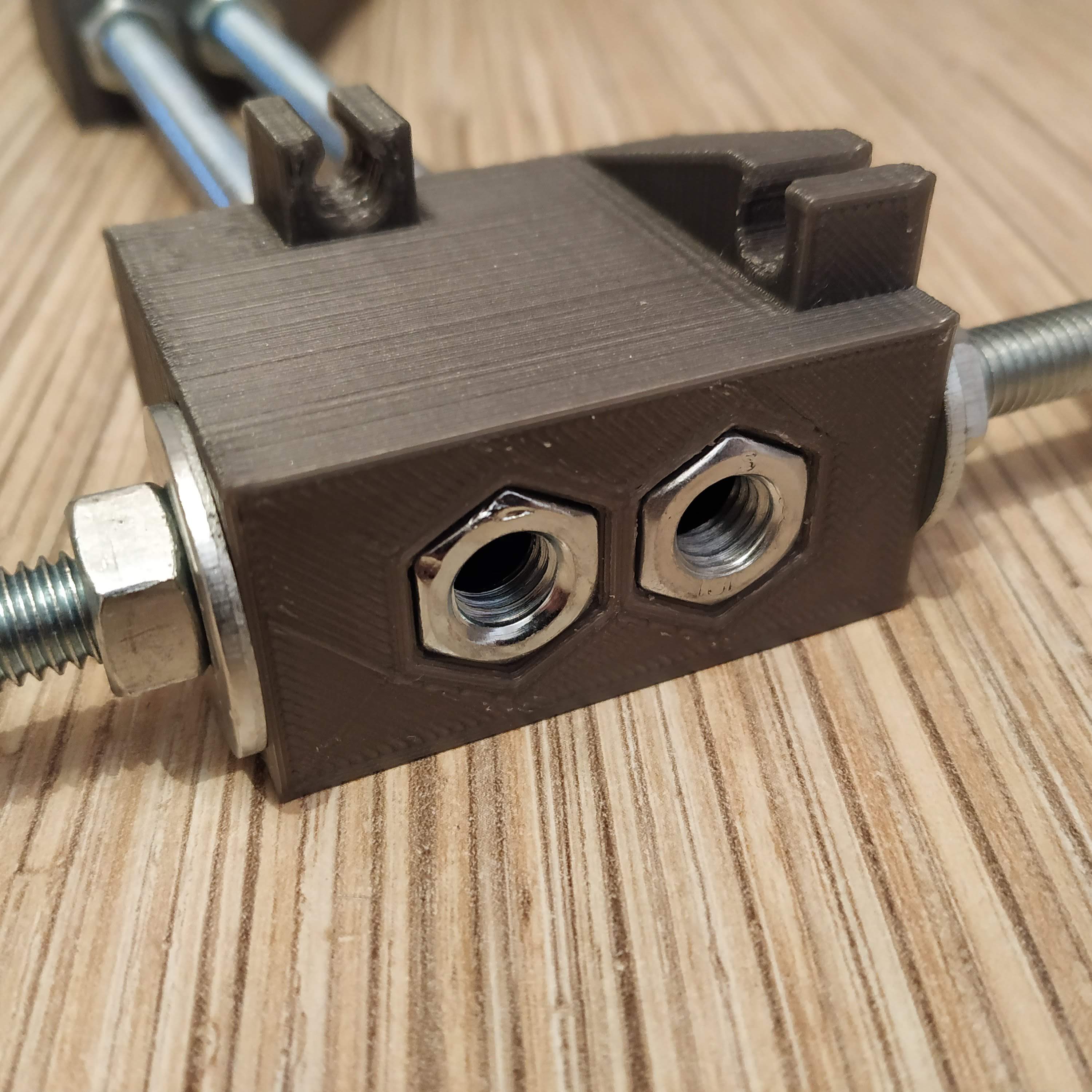
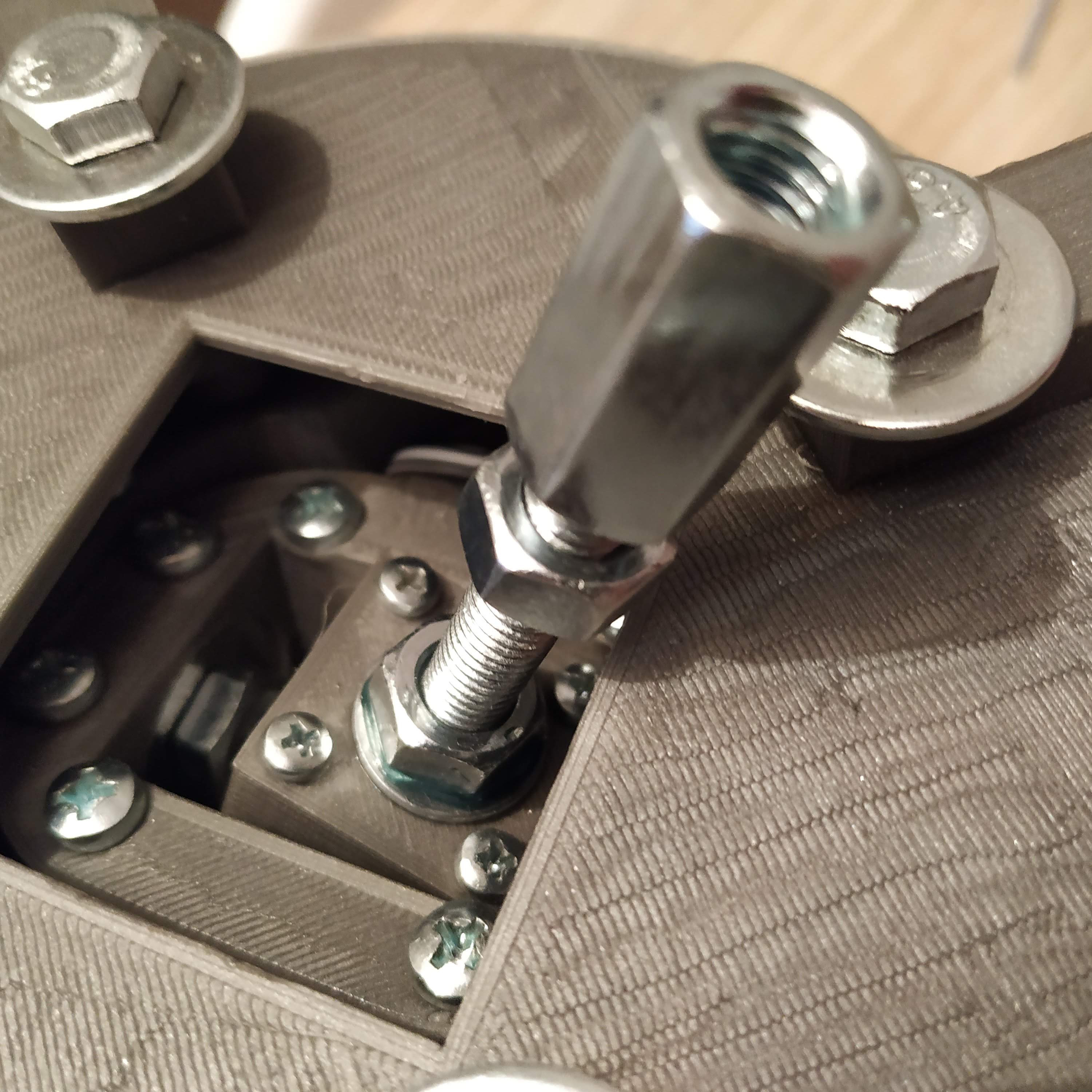
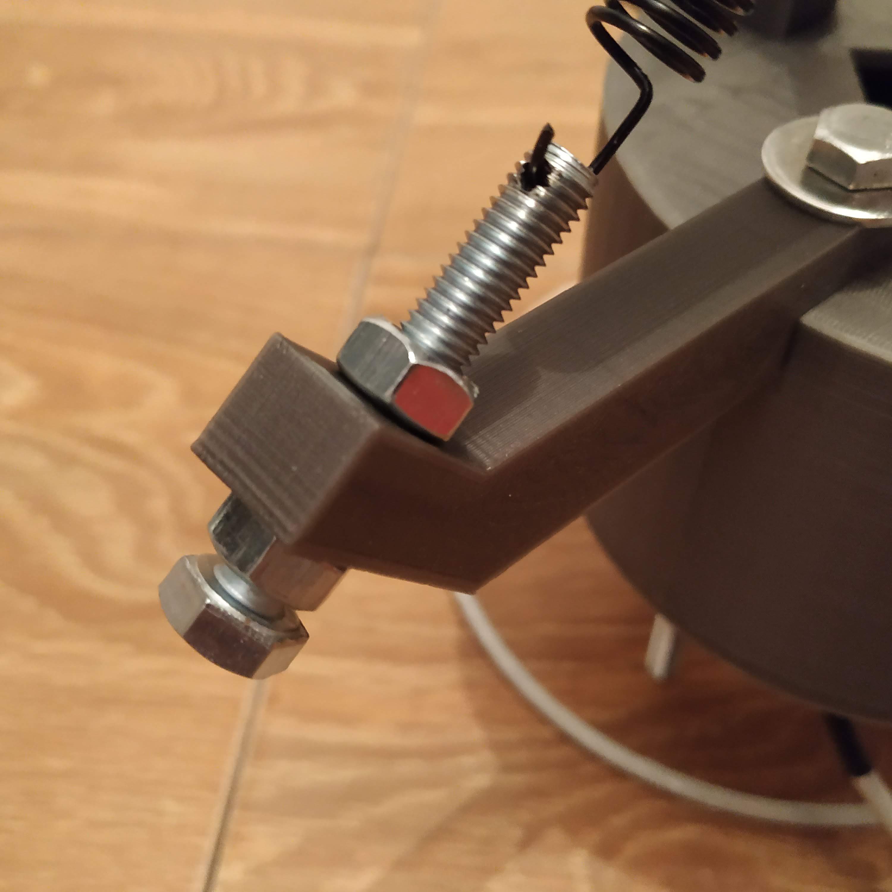
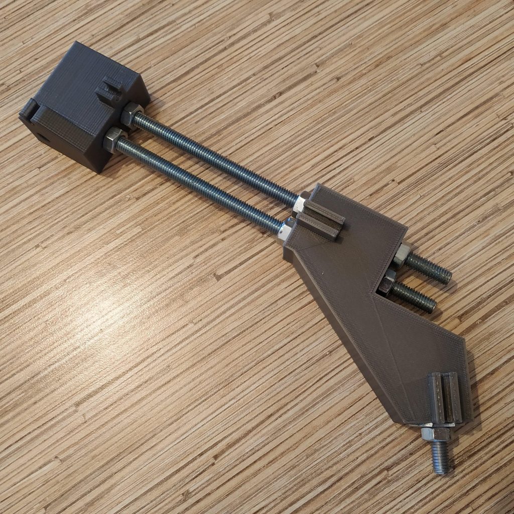
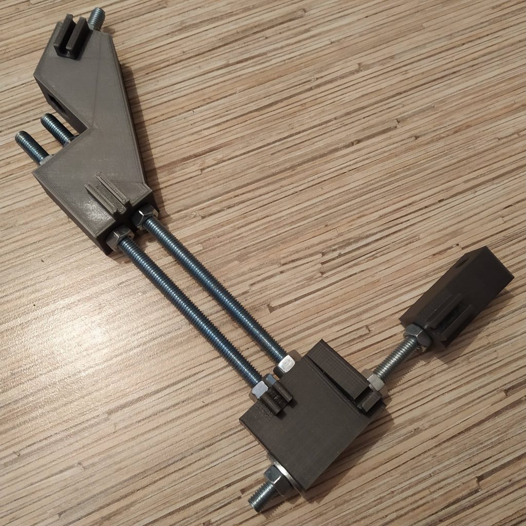
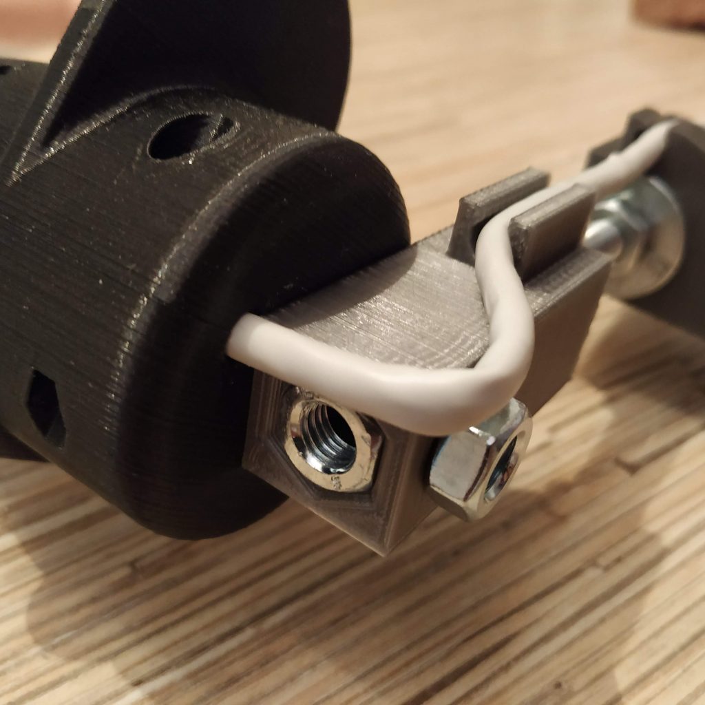
- Put a regular nut and then a connector onto the lever connector bolt. of the gimbal
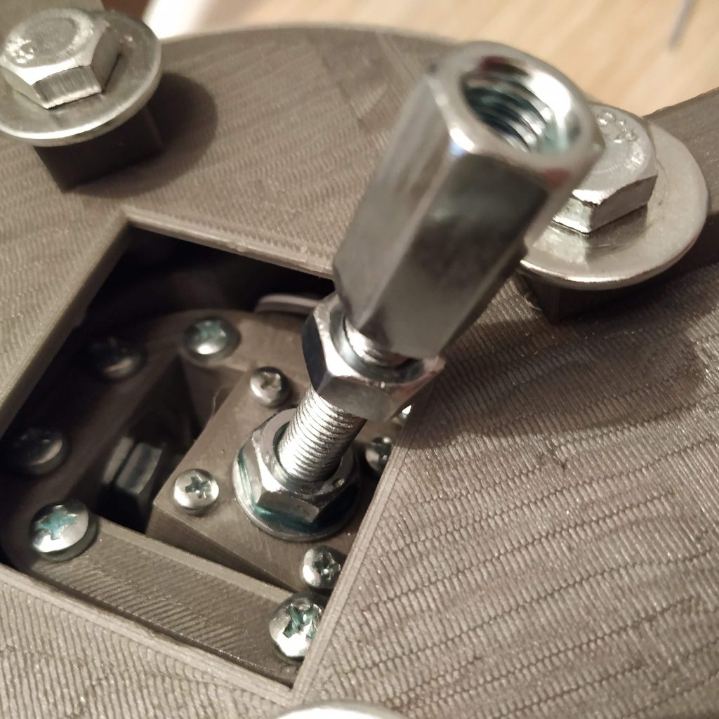
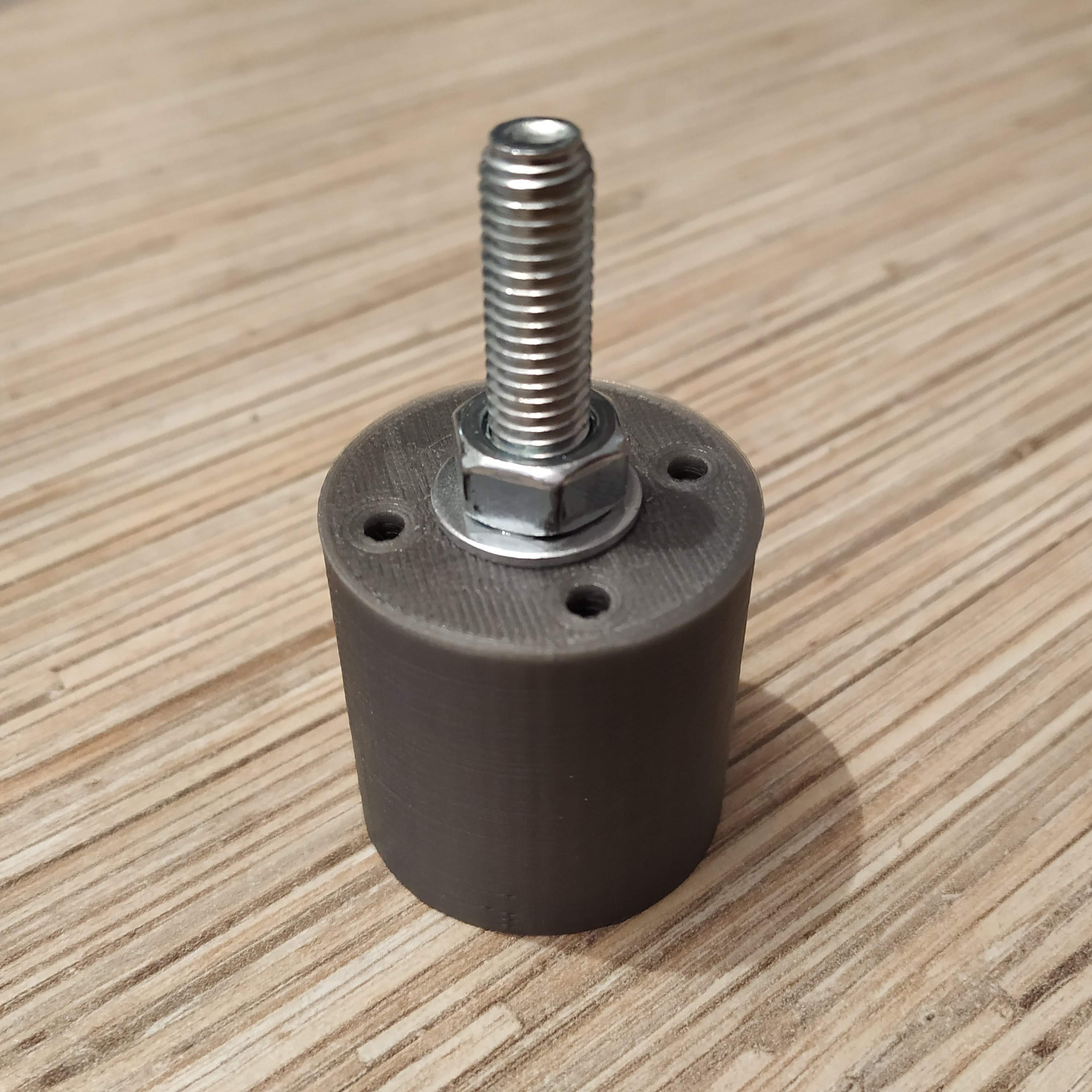
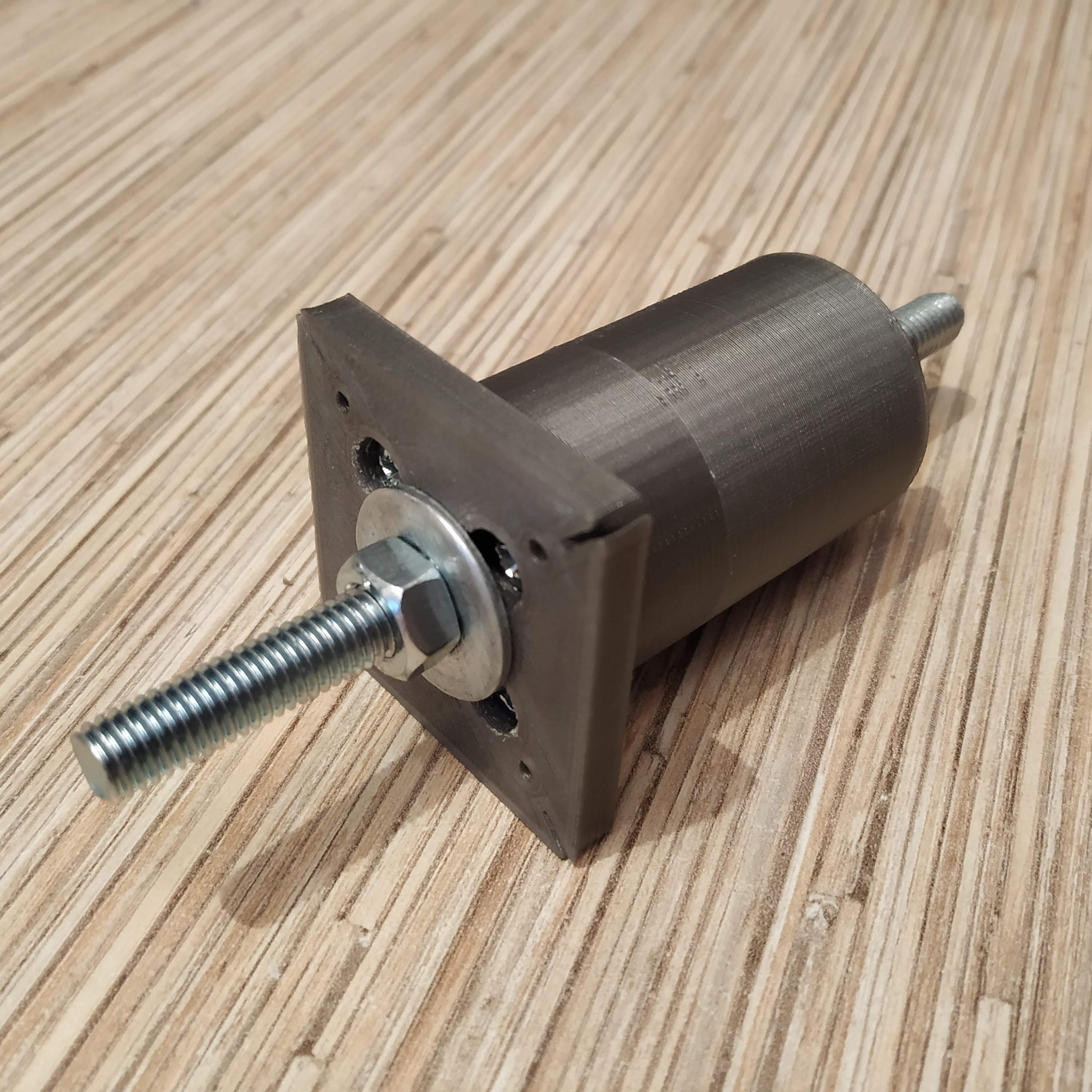
- Put an M8x60mm bolt into the lever connector part 4. Use a reinforced washer and a nut to press-fit the bolt into its socket, then remove them.
- Put ab M8x50mm bolt into lever connector p3. Put a washer and a nut onto the bolt. Use thread locker on the nut.
- Connect parts 3 and 4 of the lever connector with 4 M4x60mm screws and nuts. Use just a small drop of thread locker on M4 nuts. Put a reinforced washer and a nut on the bolt. Use thread locker.

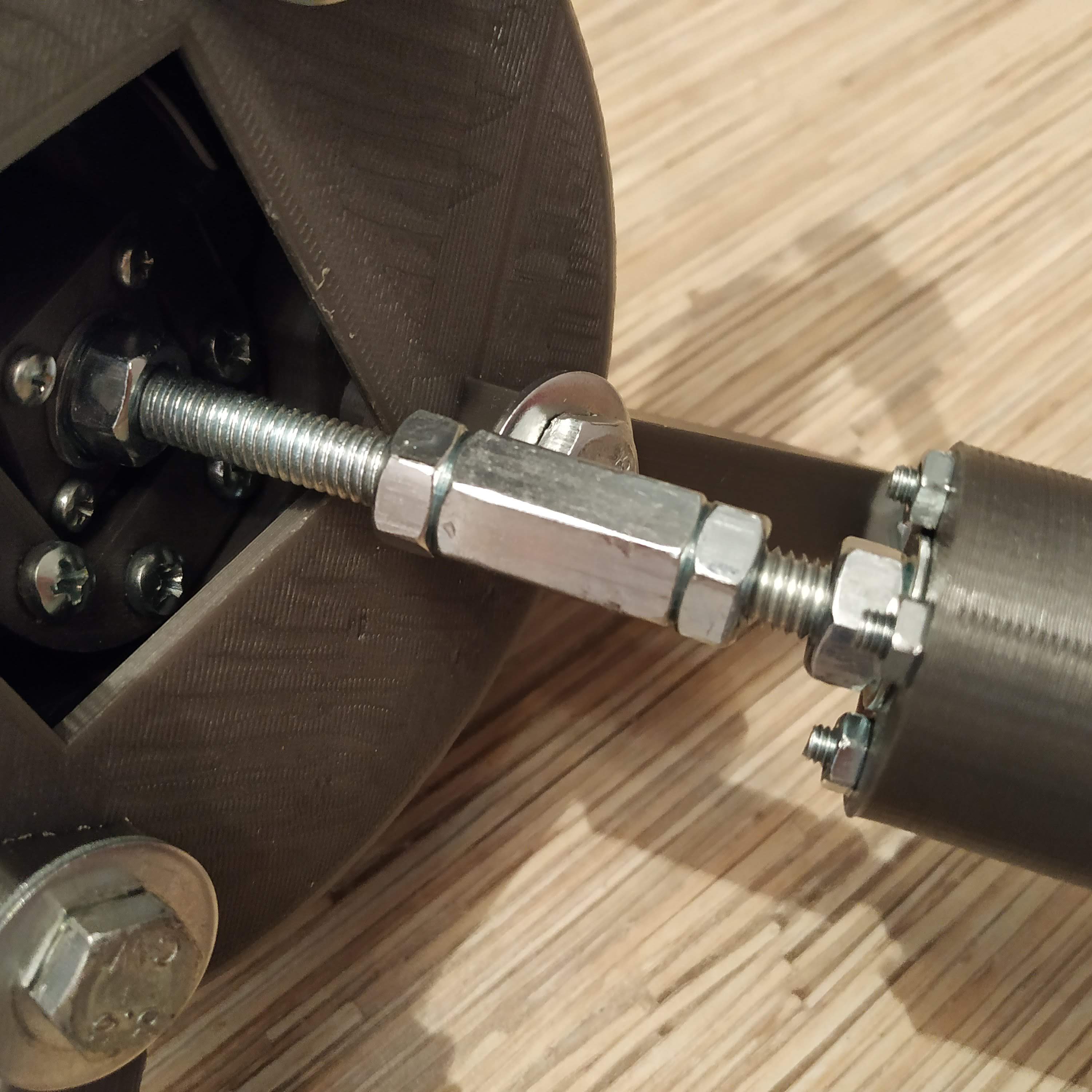
- Connect lever connector parts 3 and 4 assembly to the gimbal, using a connector nuts and two regular nuts. Position the stick connector assembly so it will be parallel to edges of the square hole in the gimbal housing, then tighten regular nuts against the connector nuts firmly. Use thread locker!

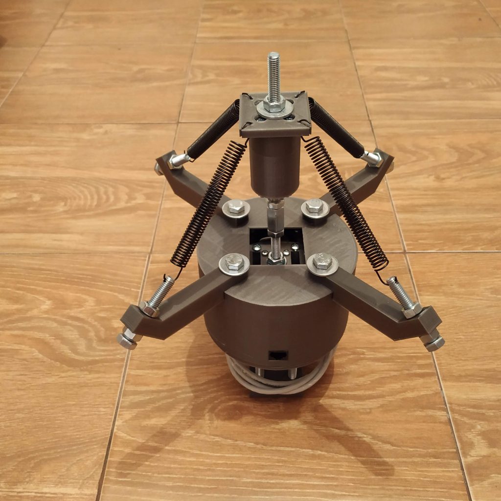
- Put springs on.
Put the housing part3 onto 4 bolts of the housing lid.

Congratulations, the assembly is finished! Adjust spring holders after connecting the stick so it will be centered in joy.cpl window.


If you haven’t built yourself a B8 flight stick grip and pedals yet, now is a good time to start.
This gimbal has a very nice pseudo force trim feature, designed specifically for use with springs. It works as close to a real helicopter force trim system as possible without complicating things too much mechanically.
When plugging your master controller into a USB port of your PC, make sure your stick and pedals are centered and are not moving. The controller will determine the mechanical center position automatically on every startup. To use it, simply put the stick and pedals to where you want the new “center” of axes to be and press the force trim button (top one by default, Huey-style, you can reassign it). Your controls will freeze. Let go of the stick and pedals, let them center. You will notice your controls will come to life again, and the chosen position will now be their mechanical center.
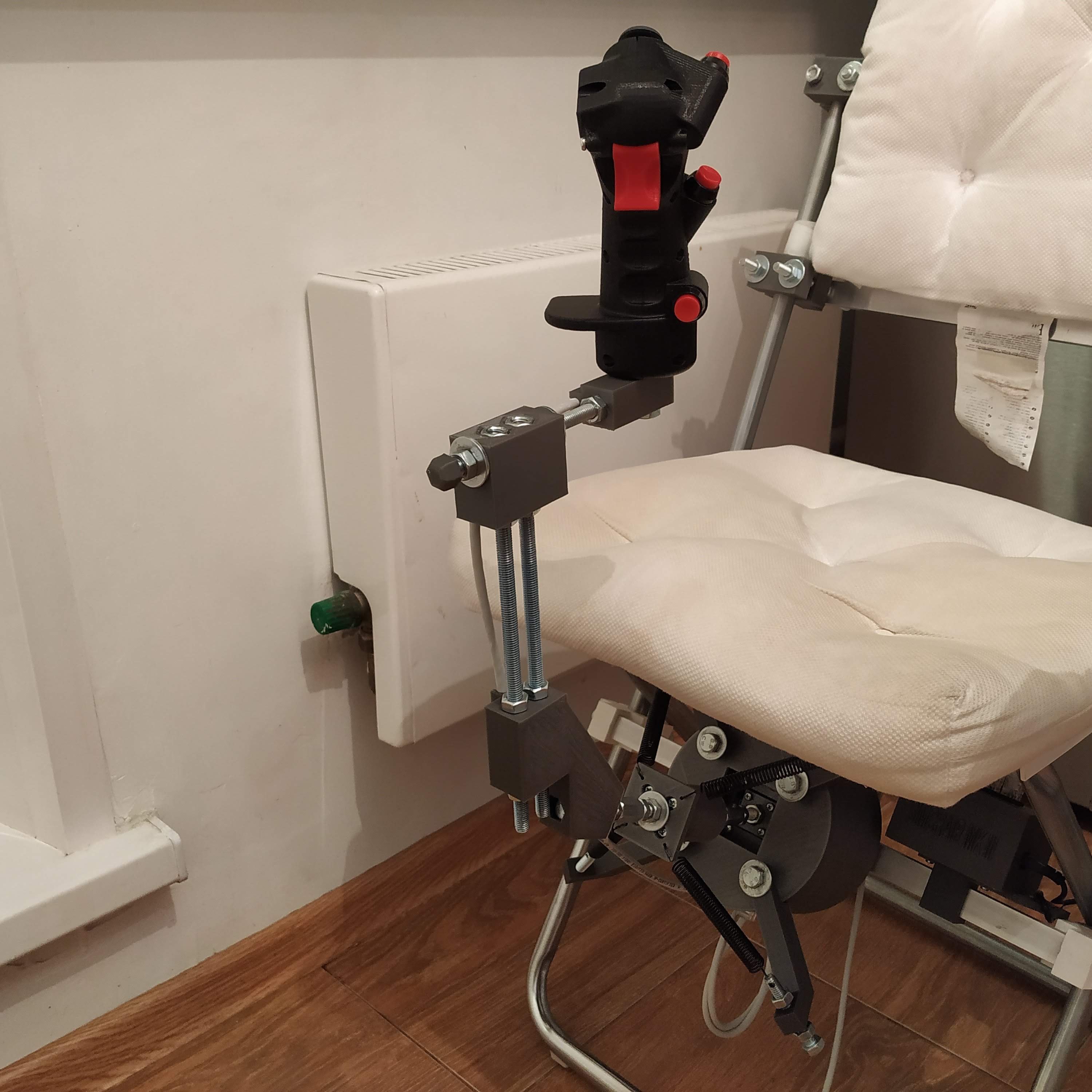
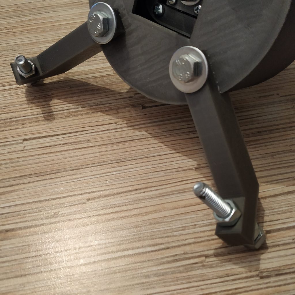
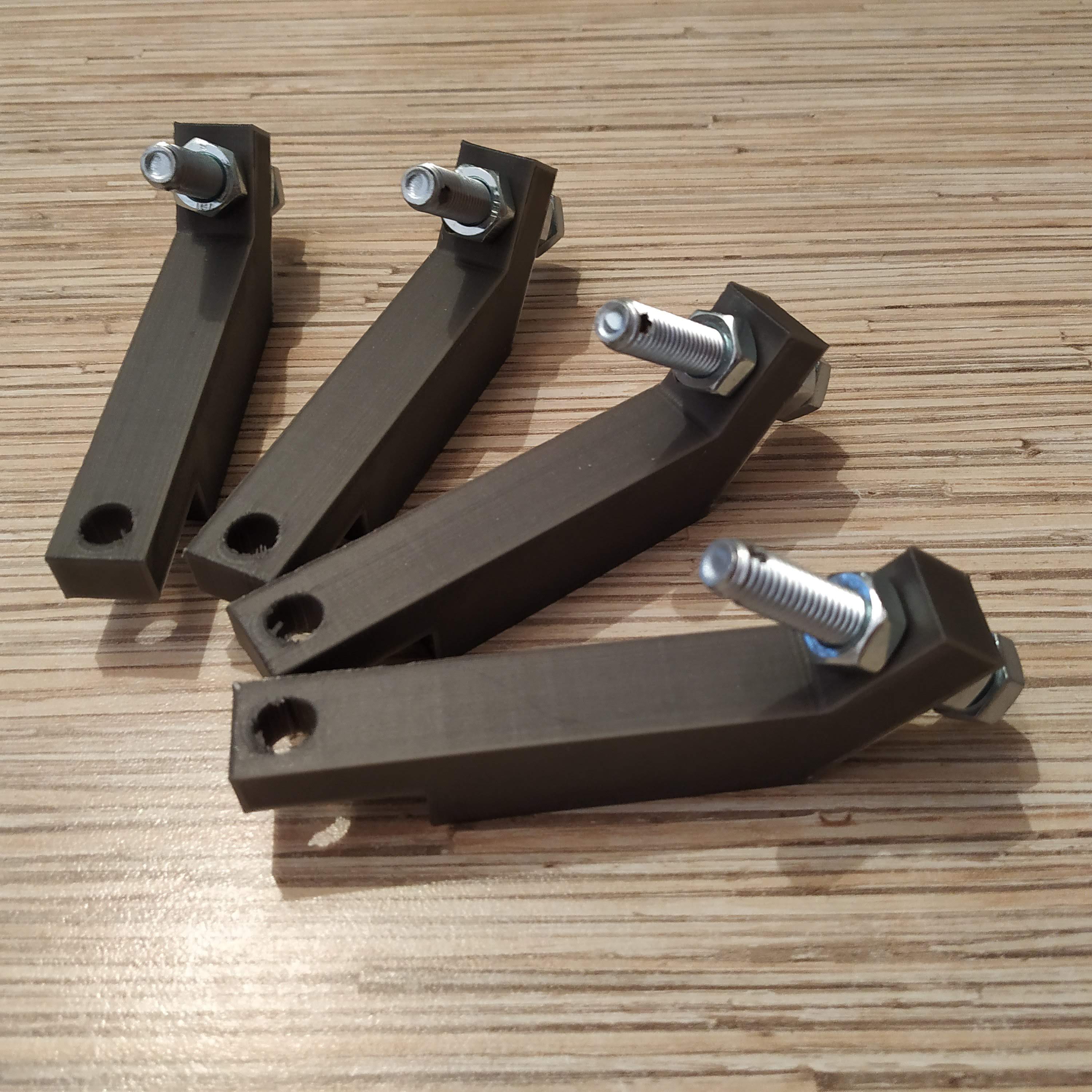
Stick frame
The bolt-on adjustable stick frame for IKEA GUNDE chair is a default option. It’s very ergonomic and can be tuned to your liking. To assemble it, follow these steps:
- Remove supports from printed parts.
- Insert 2 M8x200mm bolts to the 90mm connector part. Add nuts onto these bolts.
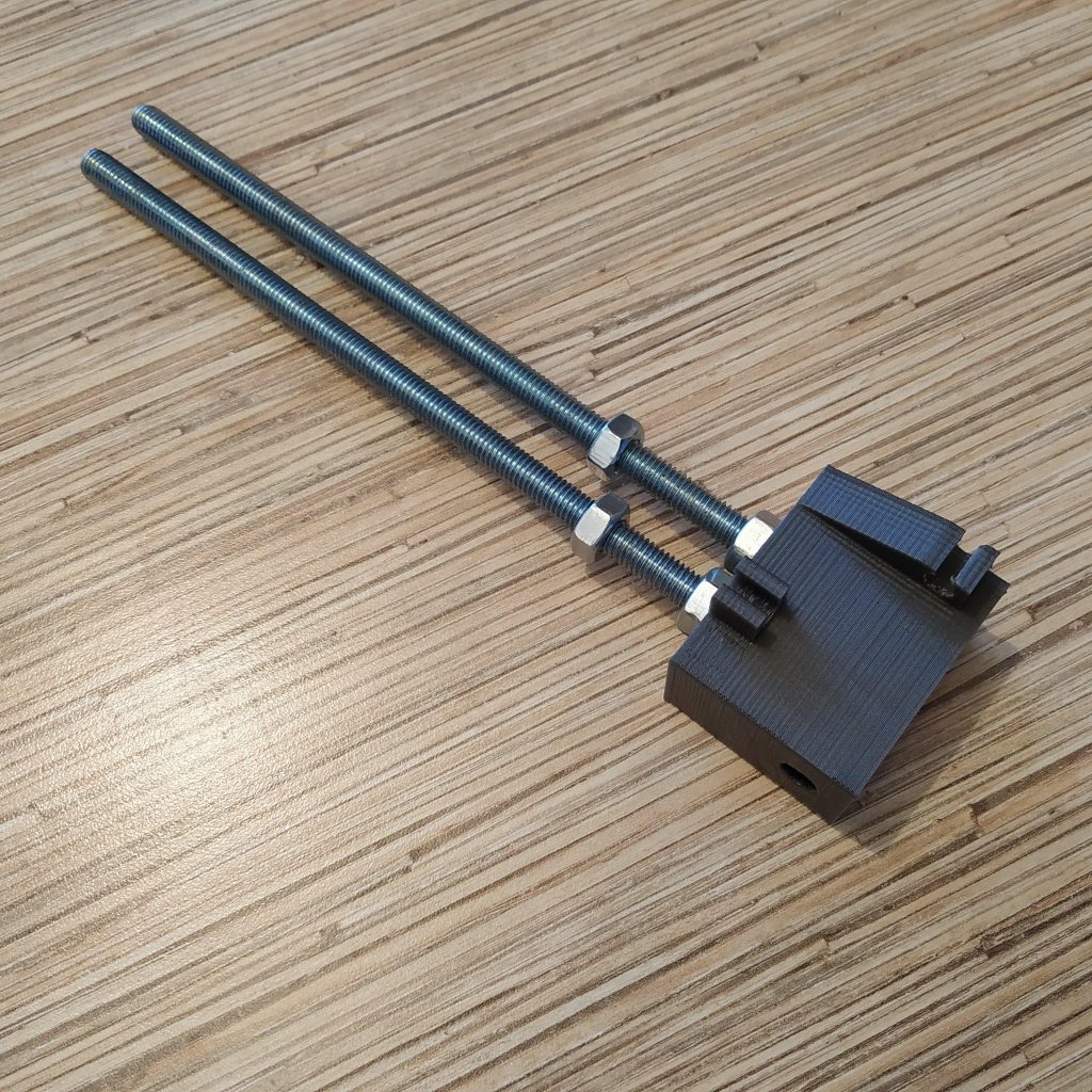
- Press-fit an M8x50mm bolt into the 150-degree connector part, put a reinforced washer onto it, fix with a nut. Use a drop of thread locker.
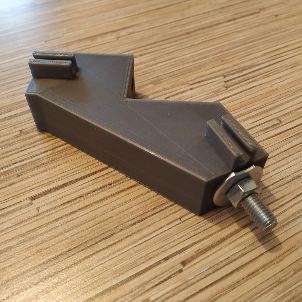
- Put 150-degree connector part onto the bolts, adjust the length to your liking, fix with nuts.
- Press-fit M8x140mm bolt into the stick grip connector. Add a nut and tighten it.
- Insert stick grip connector into 90-degree connector part. Add reinforced washers and nuts.
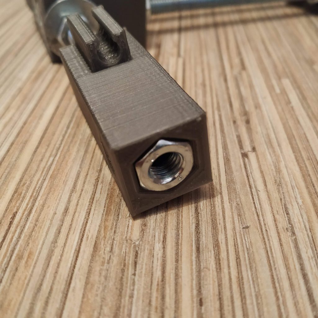
- Press-fit nuts into their sockets to reinforce parts.

- Insert the stick grip into its holder and route its cable through cable guides. Adjust all lengths and angles to your liking and tighten nuts firmly.
The stick frame is finished!