Summary
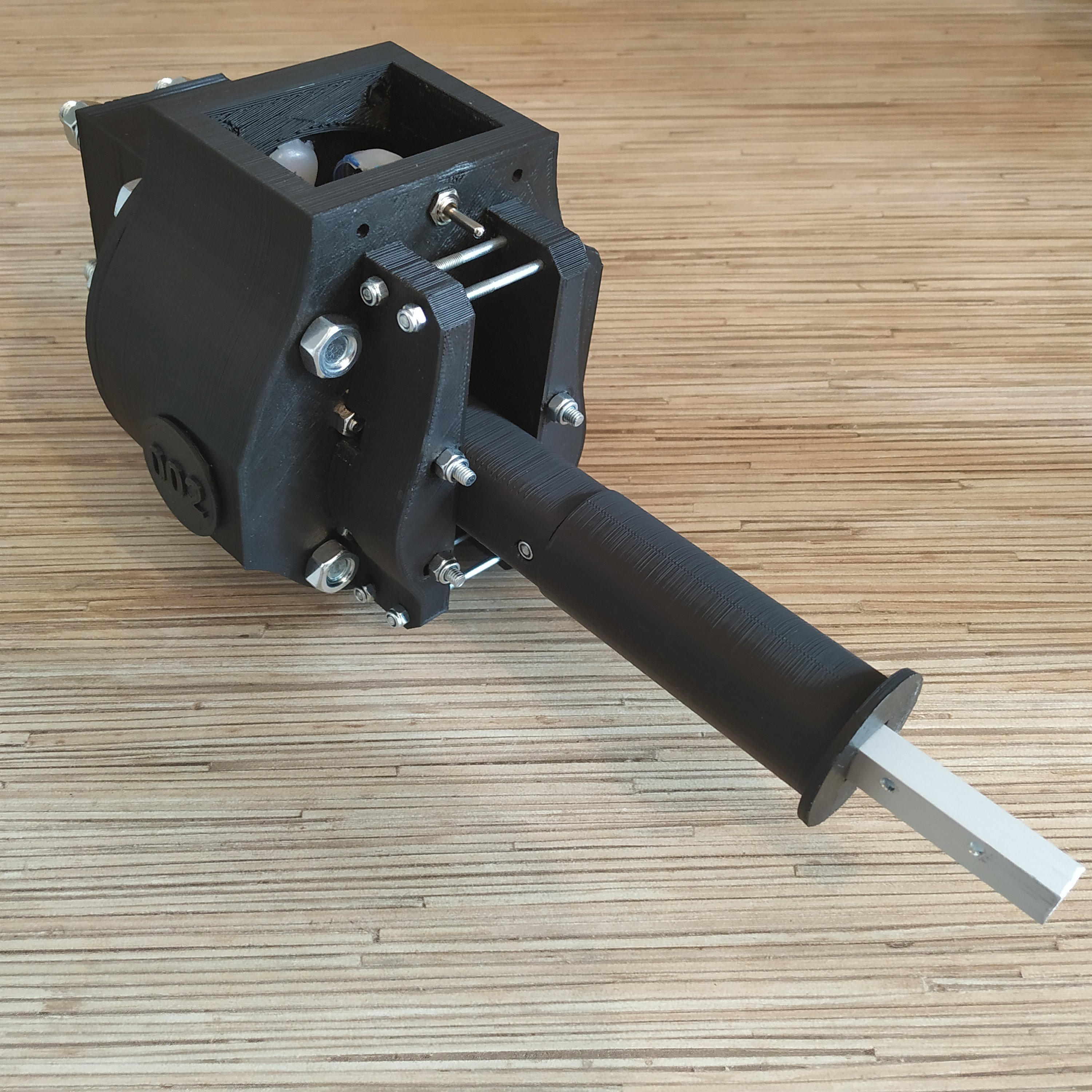
This is a universal collective base module, compatible with all levers.
Components
1 x 10x10mm aluminum square pipe
1 x 20×10 aluminum rectangular pipe for chair mounting (the mount for the IKEA GUNDE chair is included)
1 x SS495A1 hall sensor
1 x MTS-103 ON-OFF-ON switch
1 x 16K1 10KOhm LINEAR rotary potentiometer
(https://goo.gl/vbi1Zh)
1 x 6x6x4mm square magnet
1 x M6x70mm screw
2 x M6 washers (reinforced)
1 x M6 nut
2 x M6x18x8mm hubs
6 x M4x40mm screws
4 x M4x70mm screws
1 x M3x20mm screw
1 x M3 nyloc nut
4 x M4 nyloc nuts
4 x M3x50mm screws for tensioner halves contraction
4 x M8x70 bolts
4 x M8x75mm bolts
8 x M8 nuts
10 x M8 washers (regular, non-reinforced)
4 x M8 spring washers
1 x bag of M4 nuts
4 x 608 bearings (standard skateboard bearings)
1 x Arduino Pro mini
1 x Simchair MKIV I2C controller (use MKIII one for now)
super glue (cyanoacrylate), hot glue gun
Downloads
Assembling manual
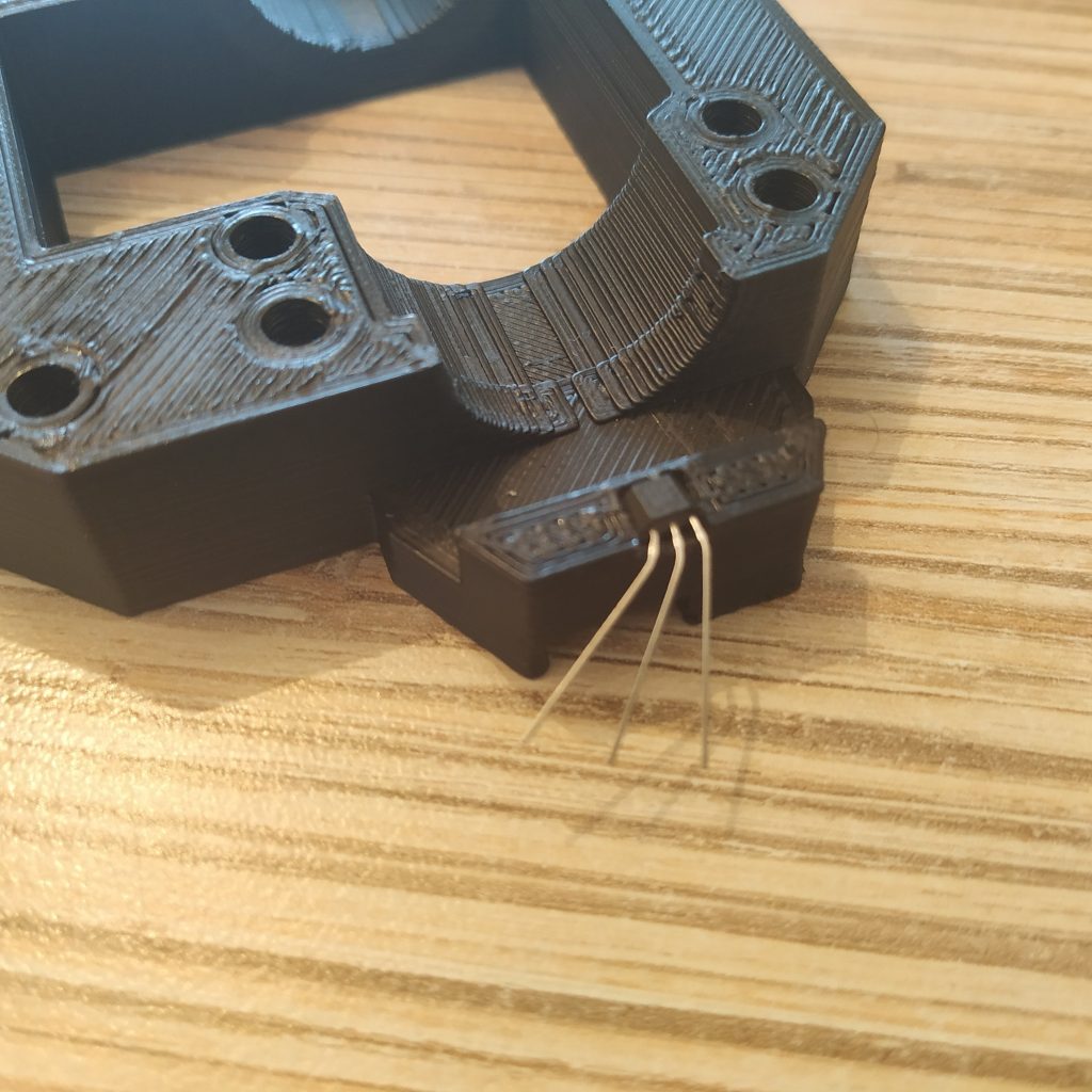
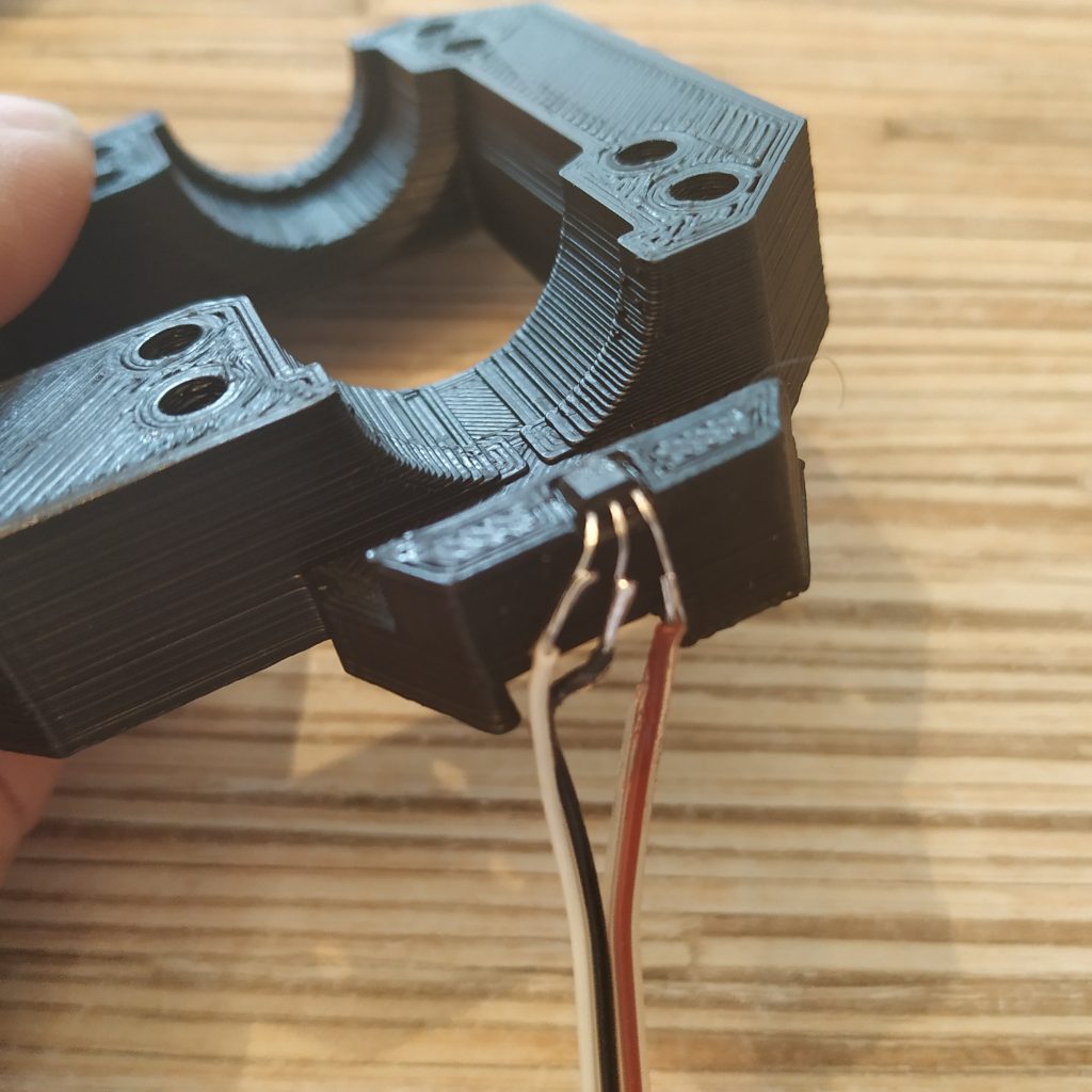
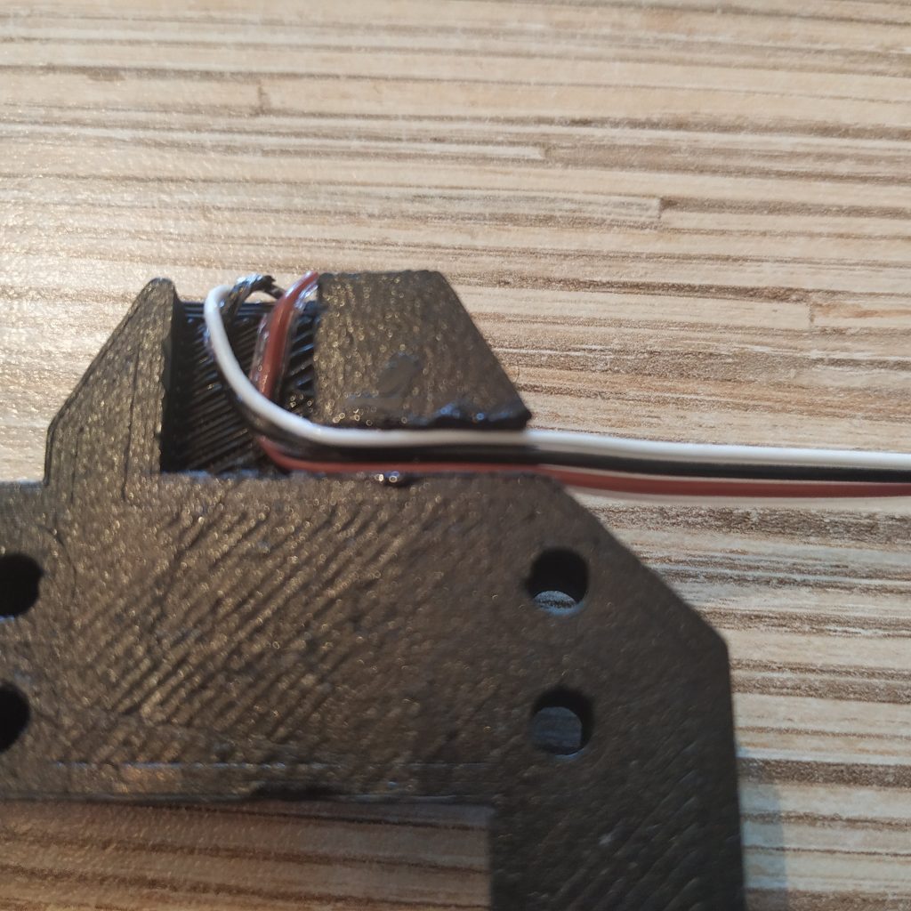
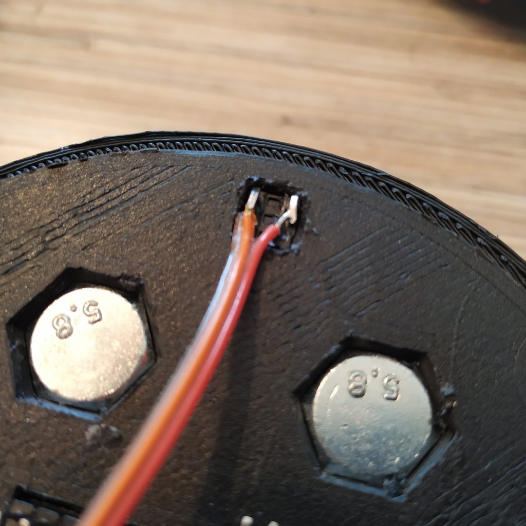
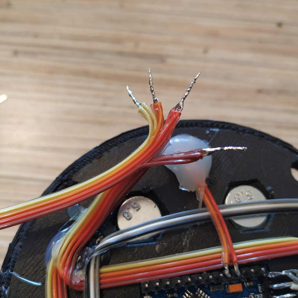
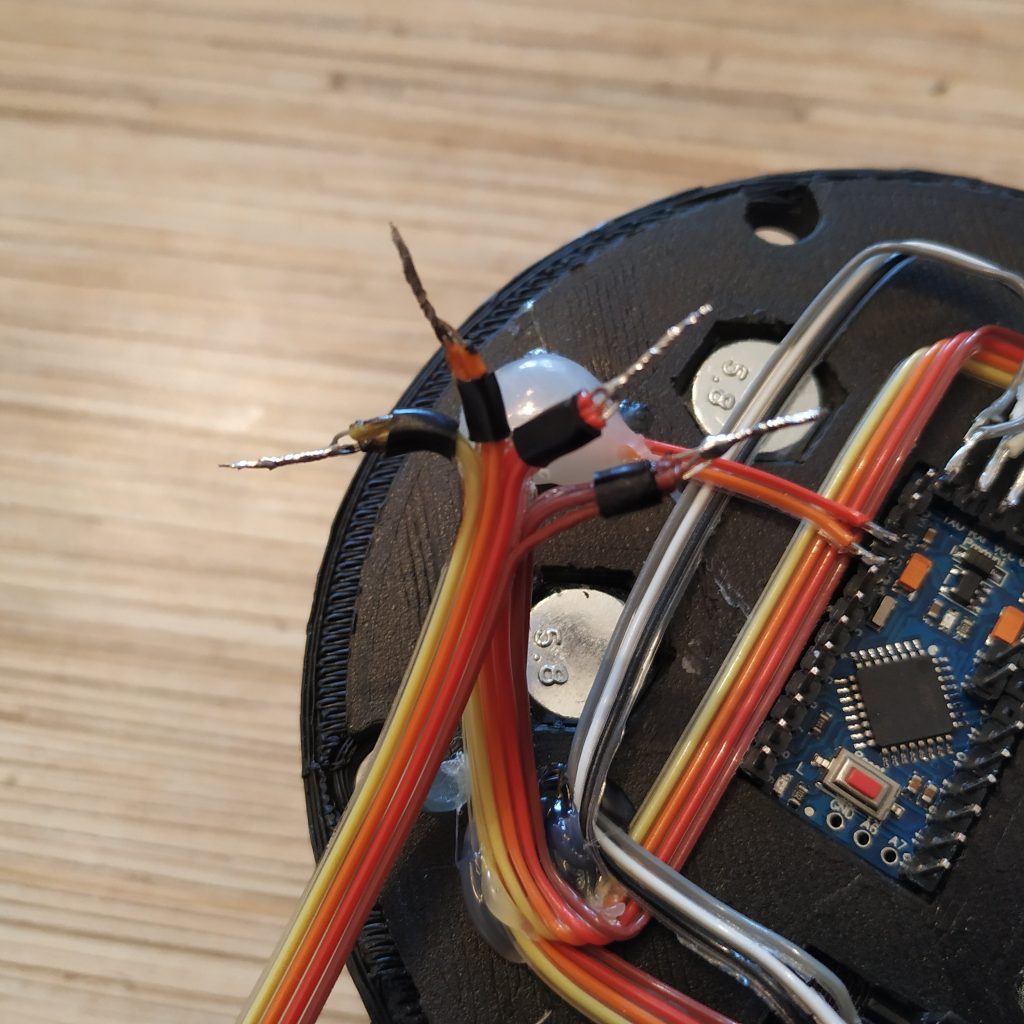
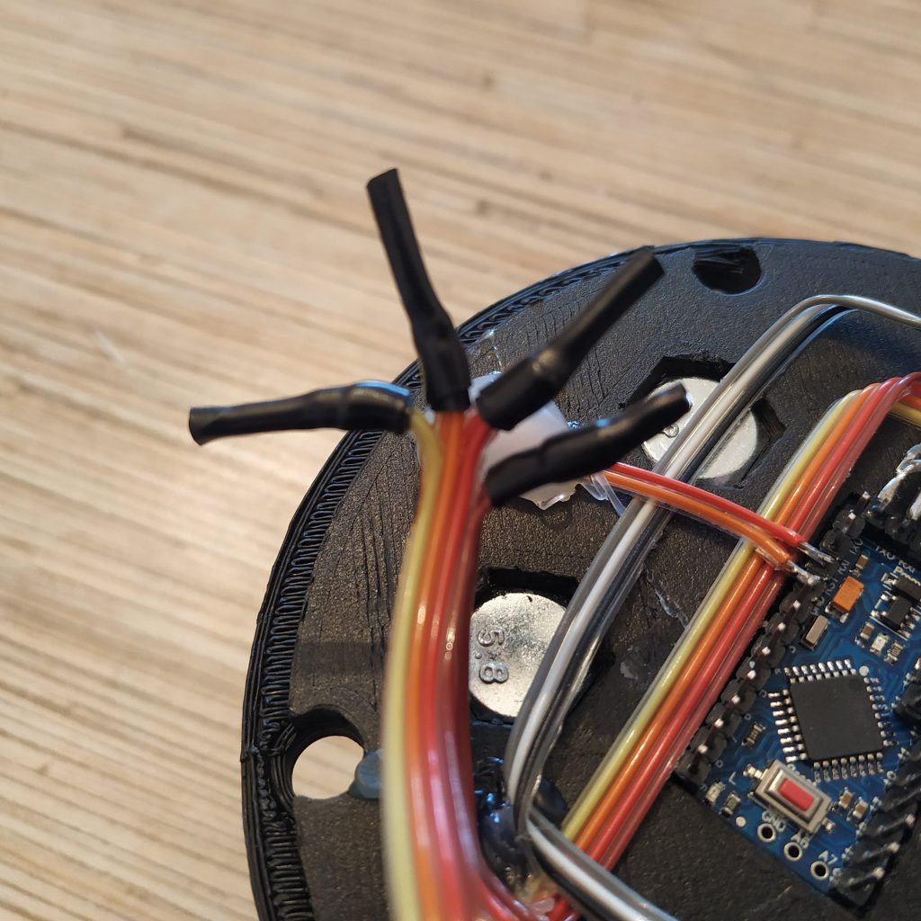
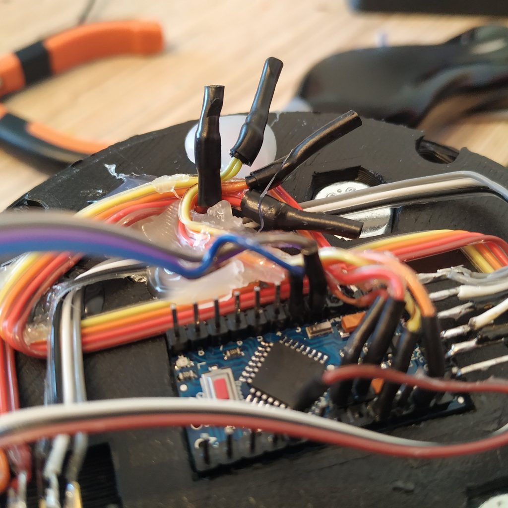
1. Insert SS495A1 into its socket in the top part of the lever frame (use a drop of super glue to fix it there) and solder its wires. Route wires as shown on the 3rd picture, use some glue as necessary.
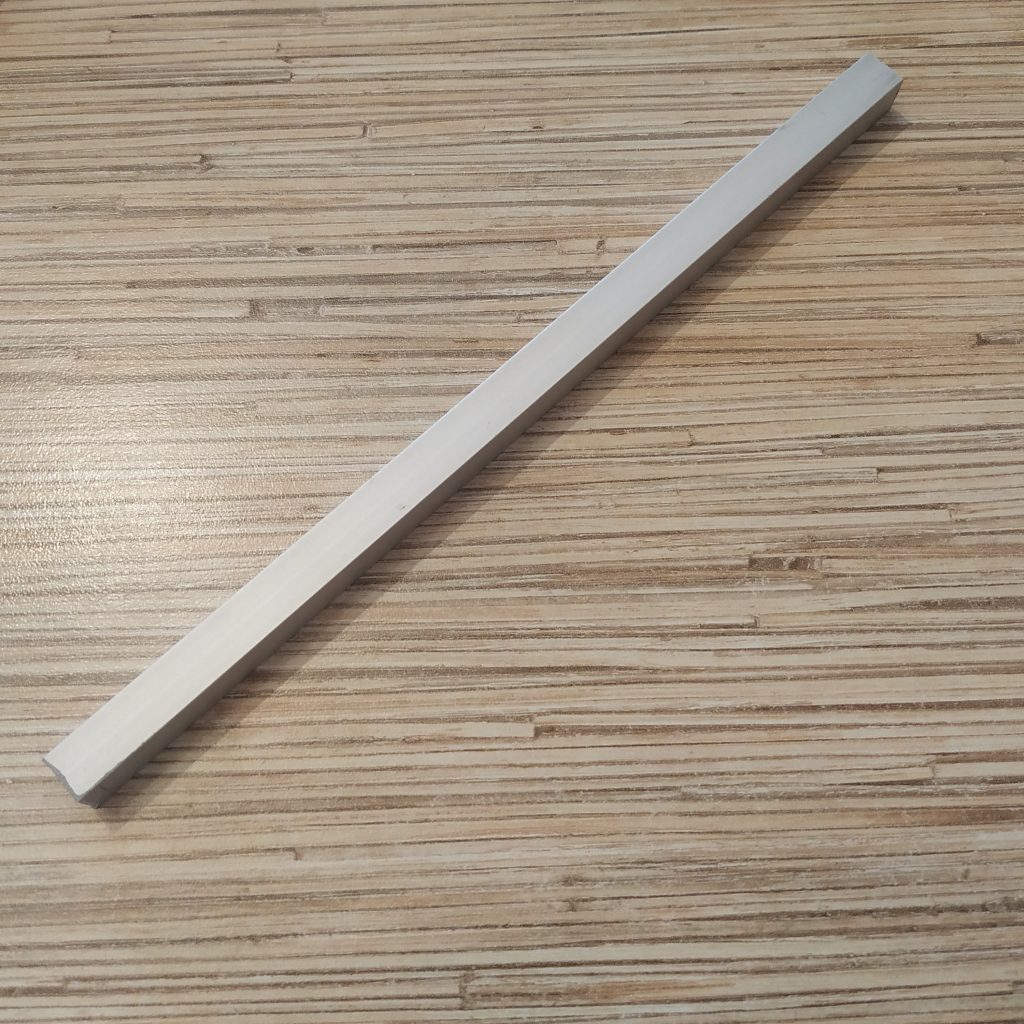
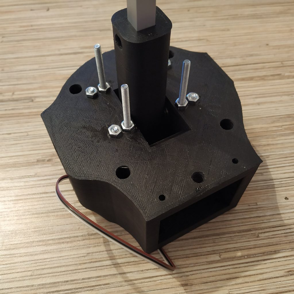
2. Cut off a piece of 10mm square aluminum profile. Choose the length depending on the lever you want to build (as stated in the lever body manual, e.g. 200mm for a single throttle lever)
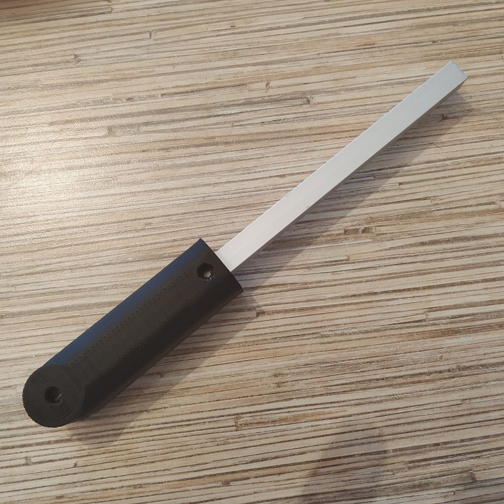
3. Put the lever connector part onto the rail.
4. Drill a 3mm hole throught tbe rail and insert an M3x20mm screw with a nyloc nut.
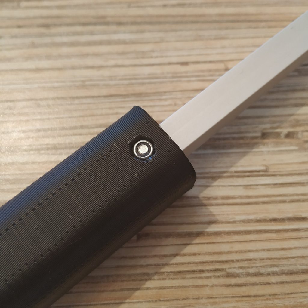
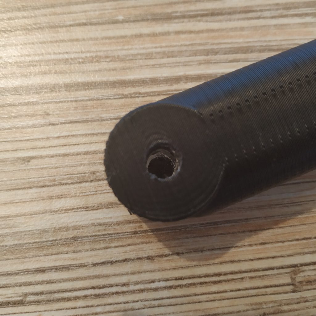
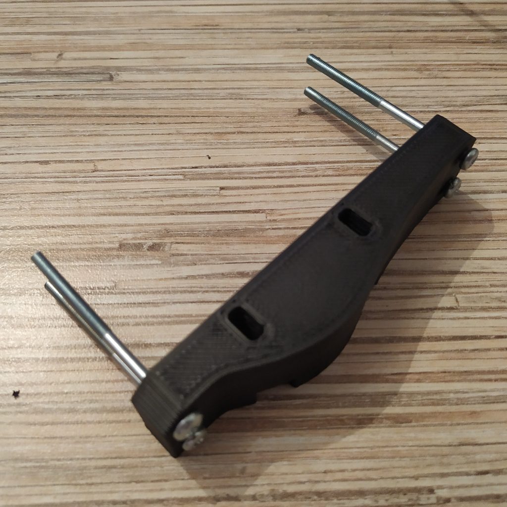
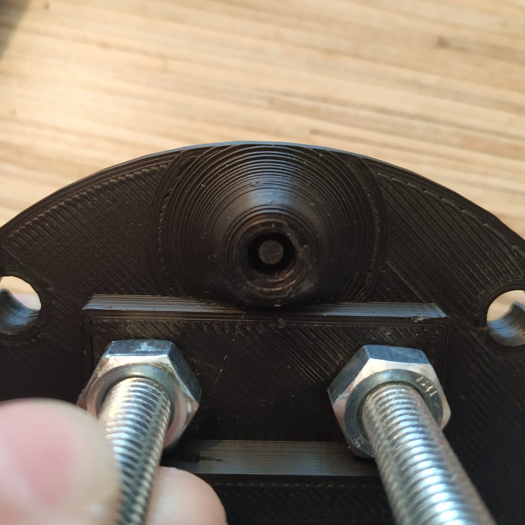
5. Drill a 6mm hole for the axis through the rail with a 5,5mm drill.
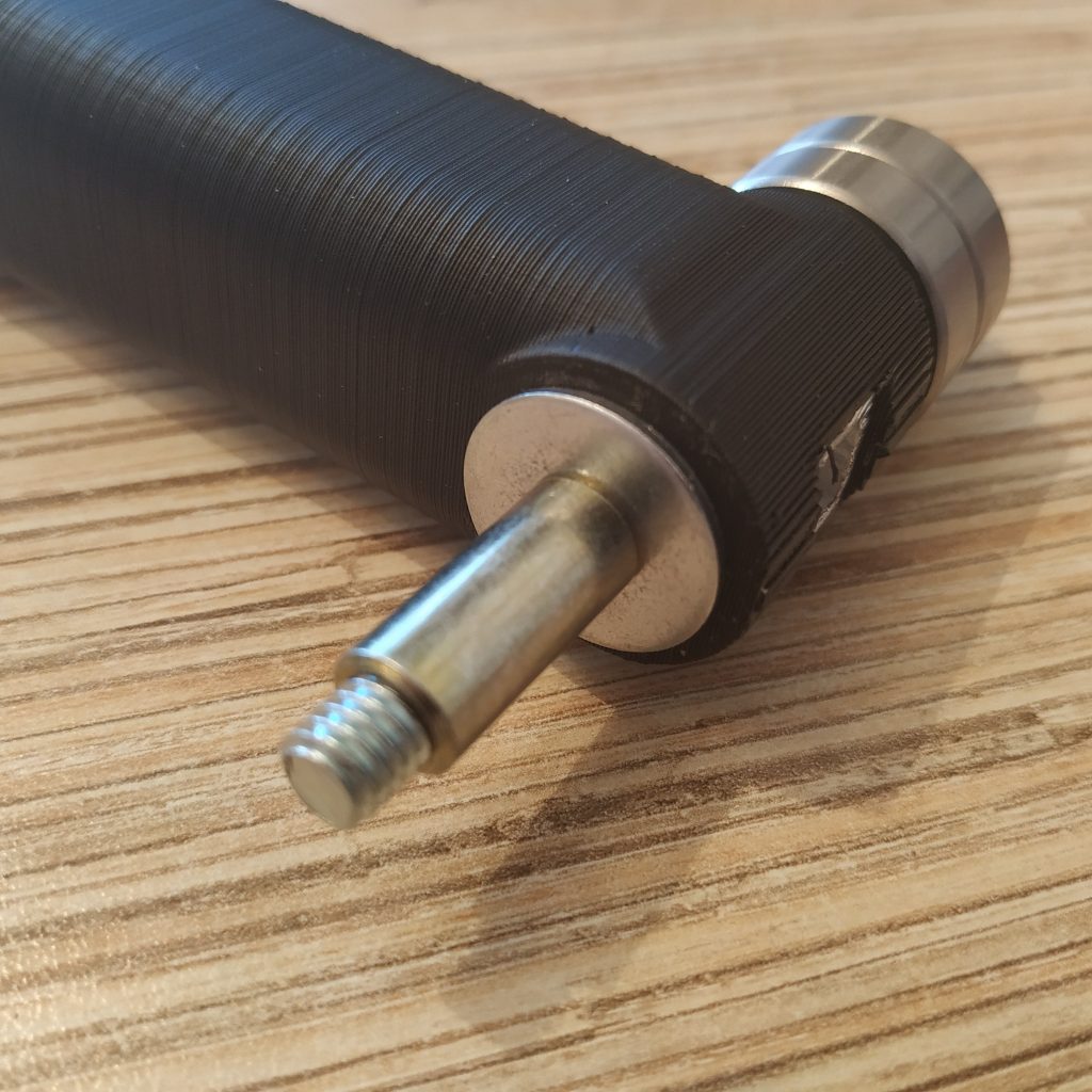
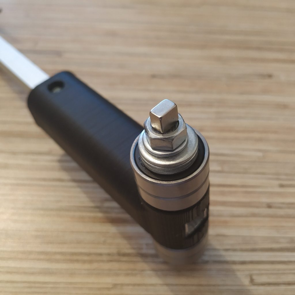
6. We will be assembling the lever axis. Start with putting an M6x8x18mm hub onto an M6x70mm bolt.
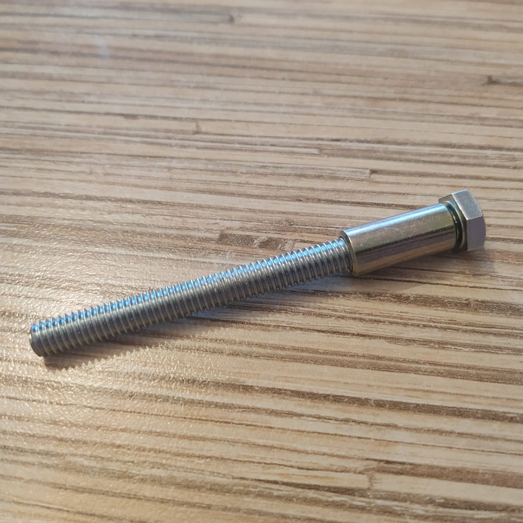
7. Put 3 M8 washers onto the hub
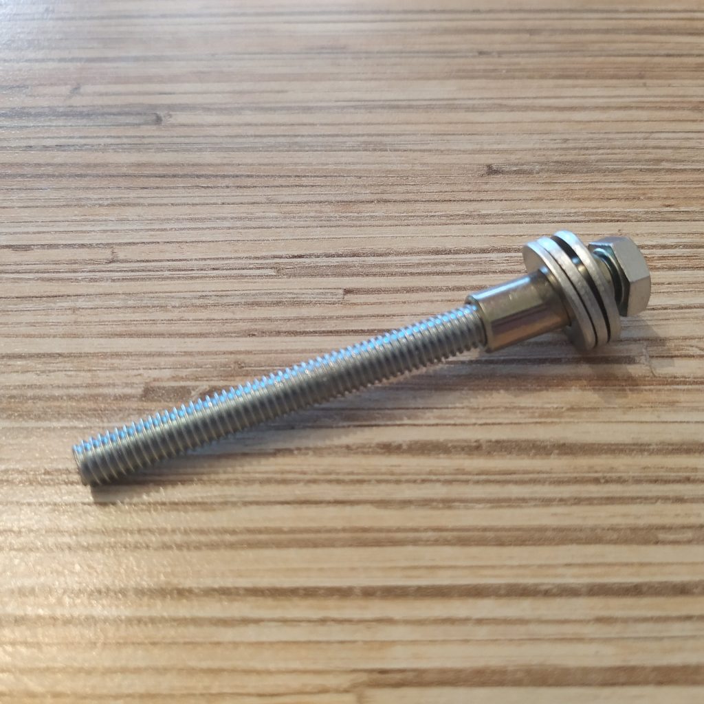
8. Put 2 bearings onto the hub
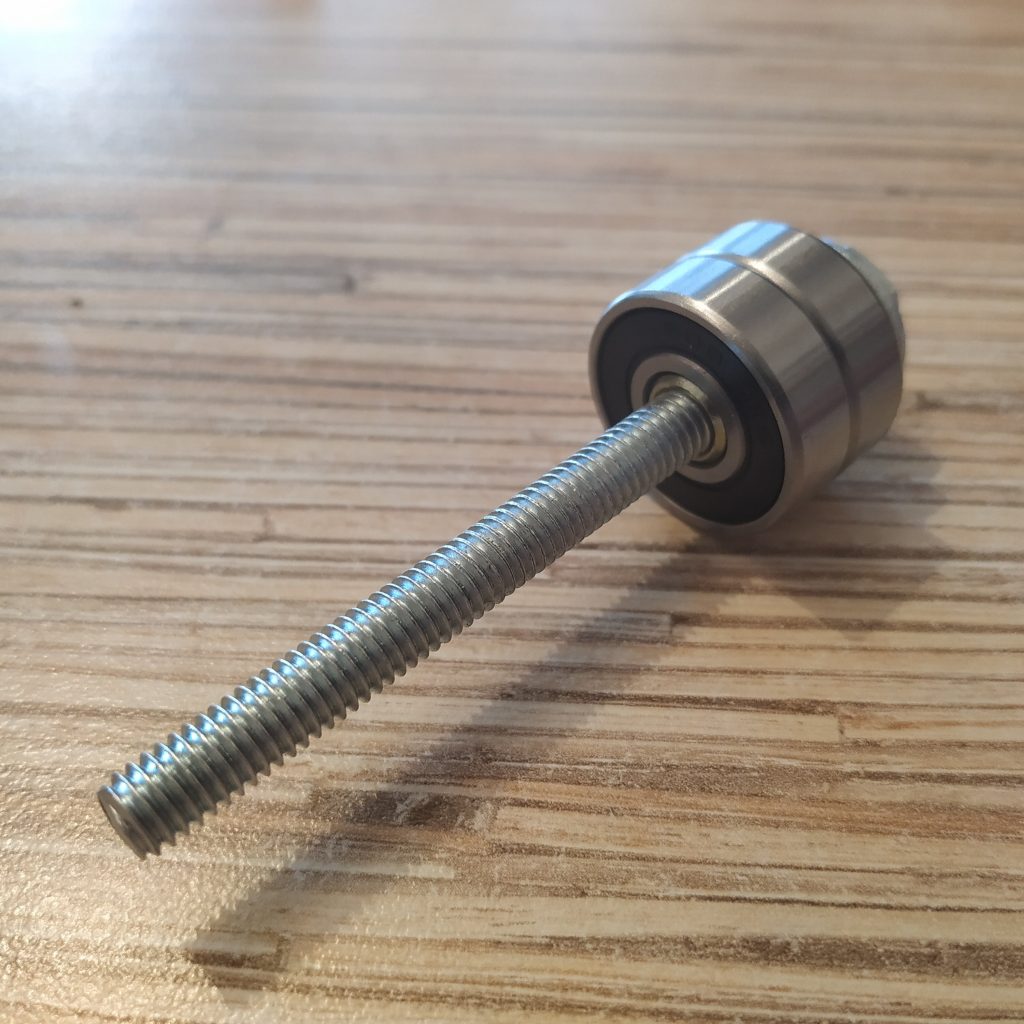
9. Put a reinforced M6 nut onto the bolt
10. Put an axis though the lever connector part
11. Put a reinforced nut onto the M6 bolt.
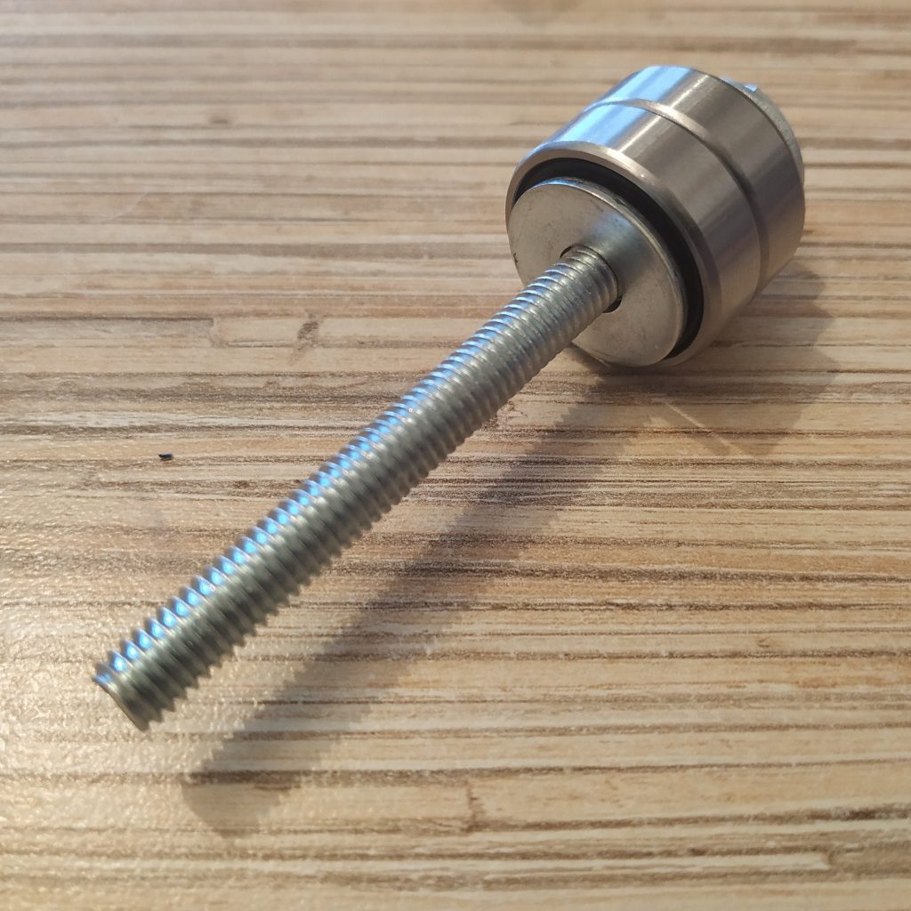
12. Put another hub onto the bolt.
13. Put 2 bearings onto the hub
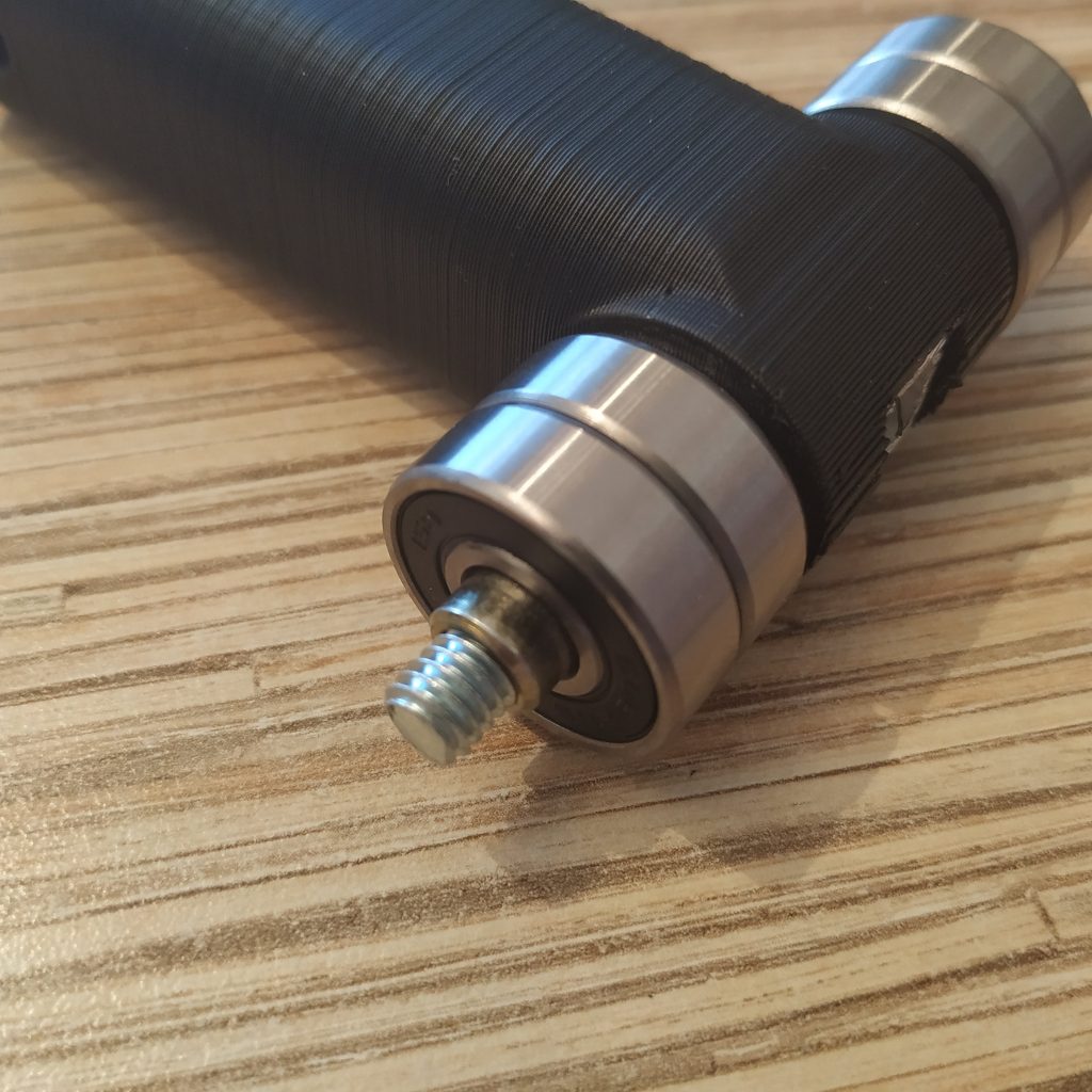
14. Add 3 M8 washers
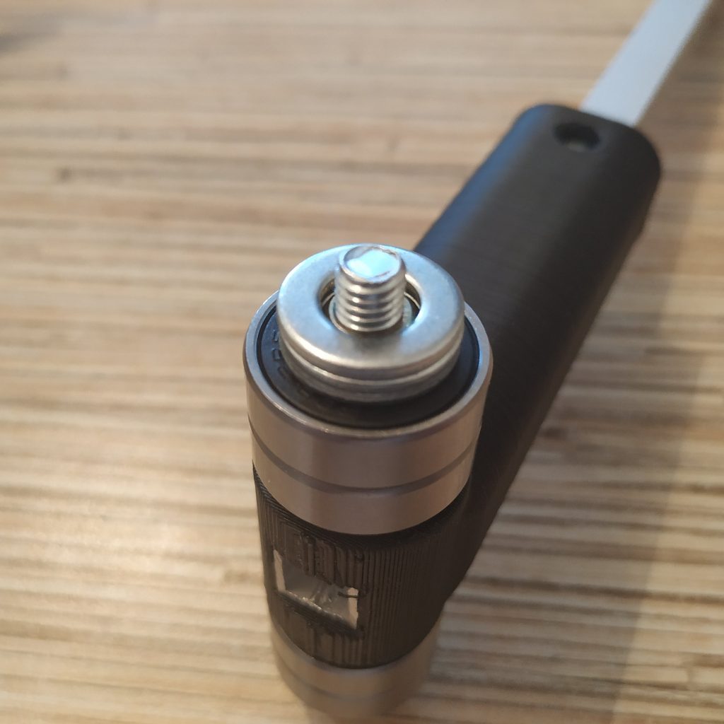
15. Put an M6 washer and a nut onto the bolt. Use thread locker to fix the nut.
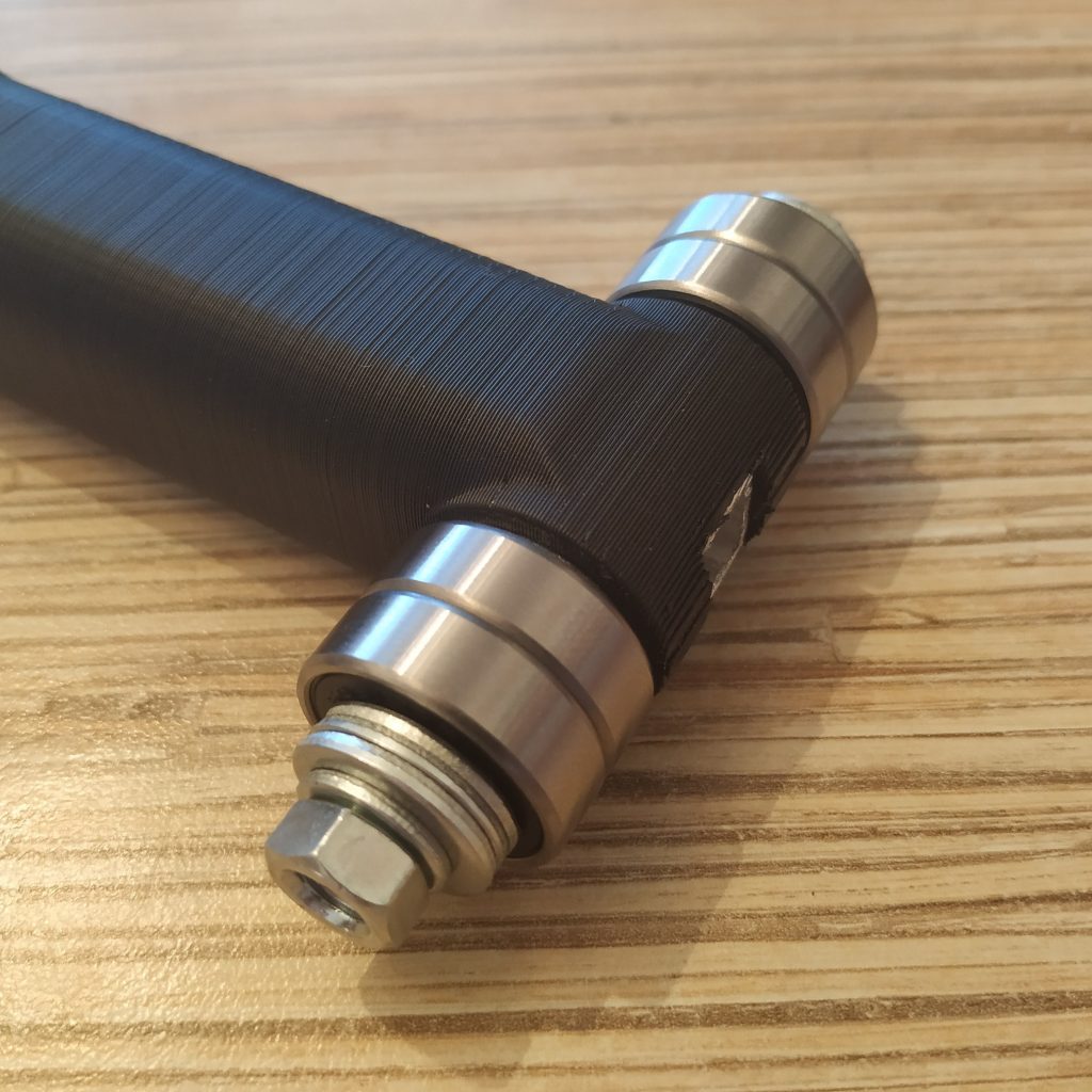
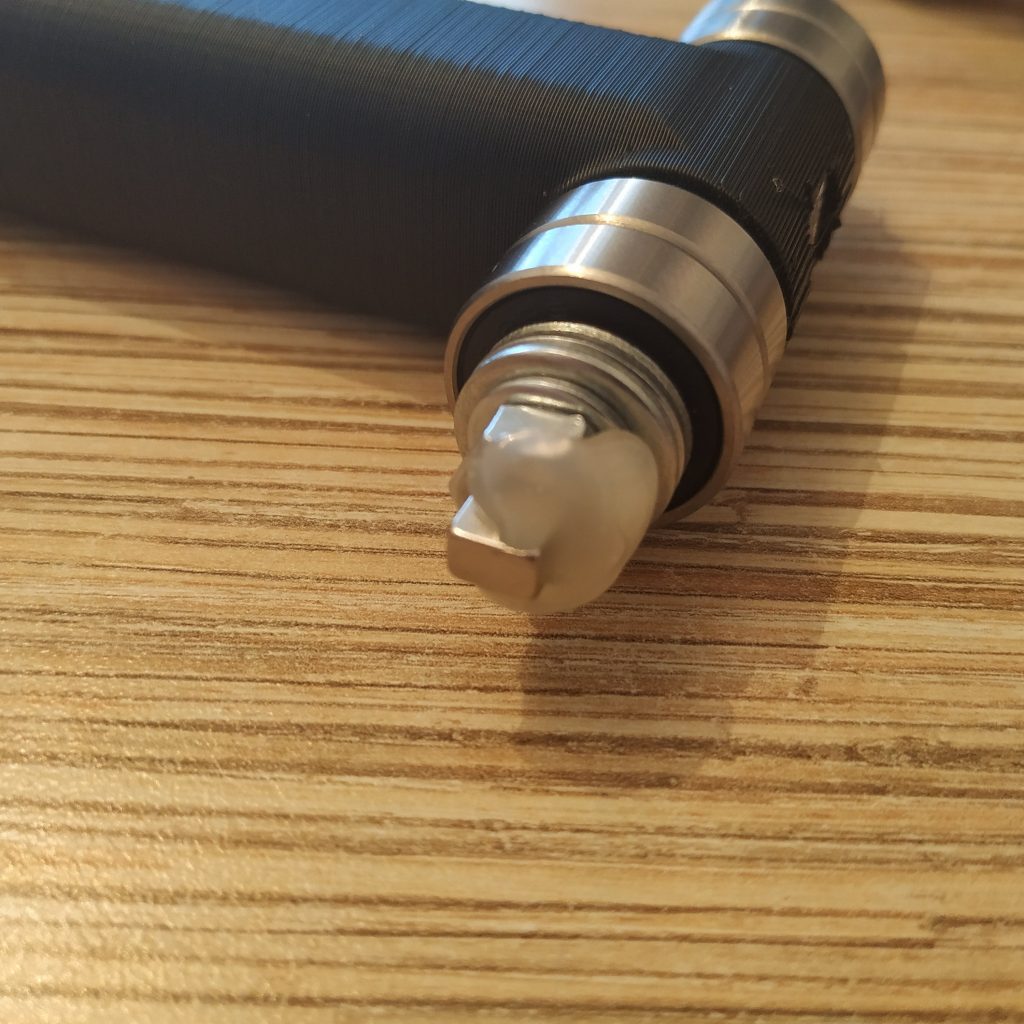
16. Put the magnet onto the nut and fix it with hot glue.
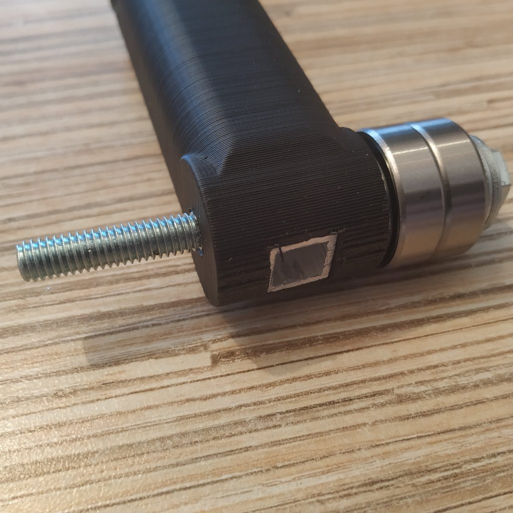
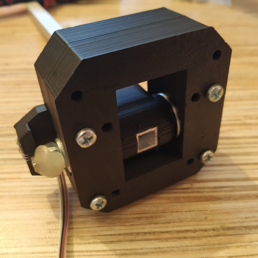
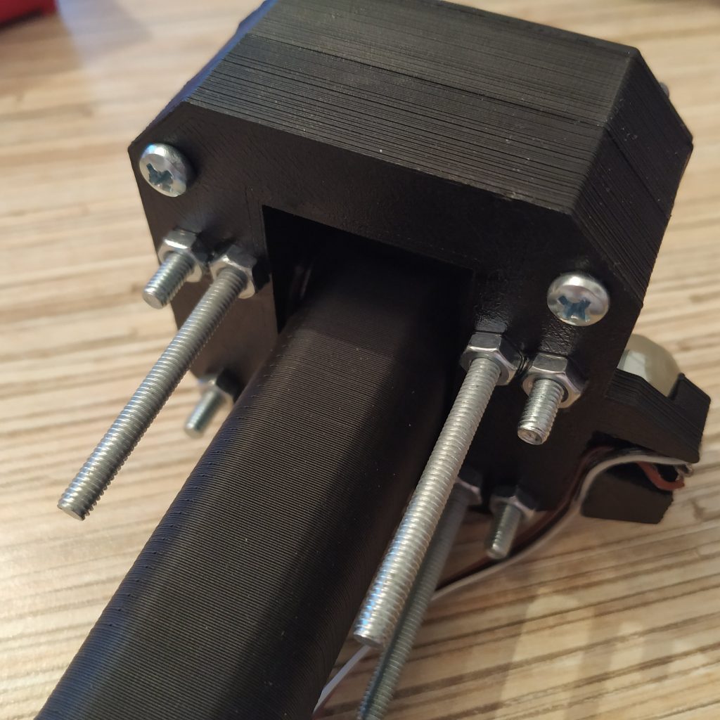
17. Insert the axis assembly into its frame.
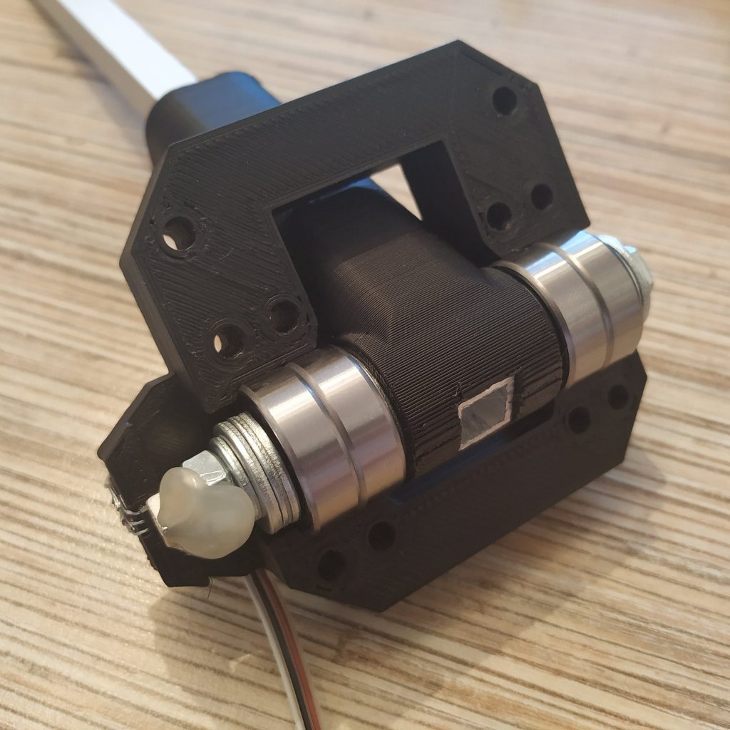
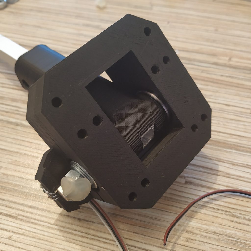
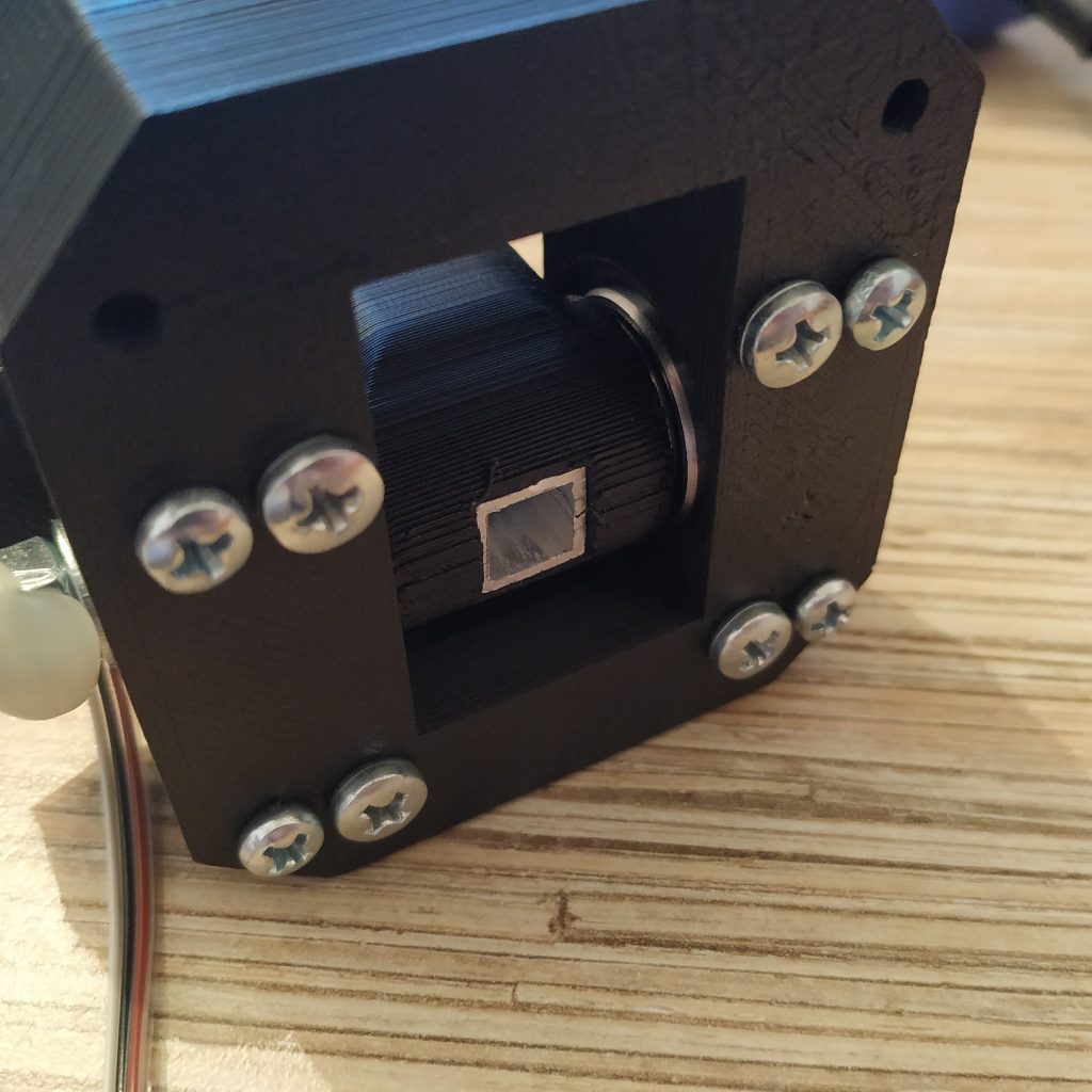
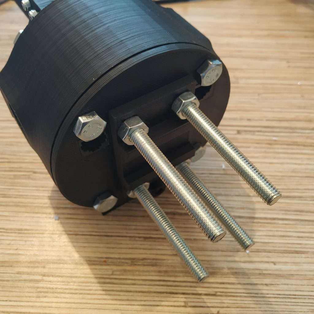
18. Insert 4 M4x40mm bolts into the frame as shown on the picture below, put nuts from the other side, use thread locker.
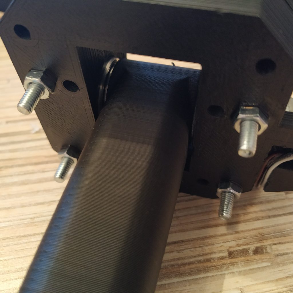
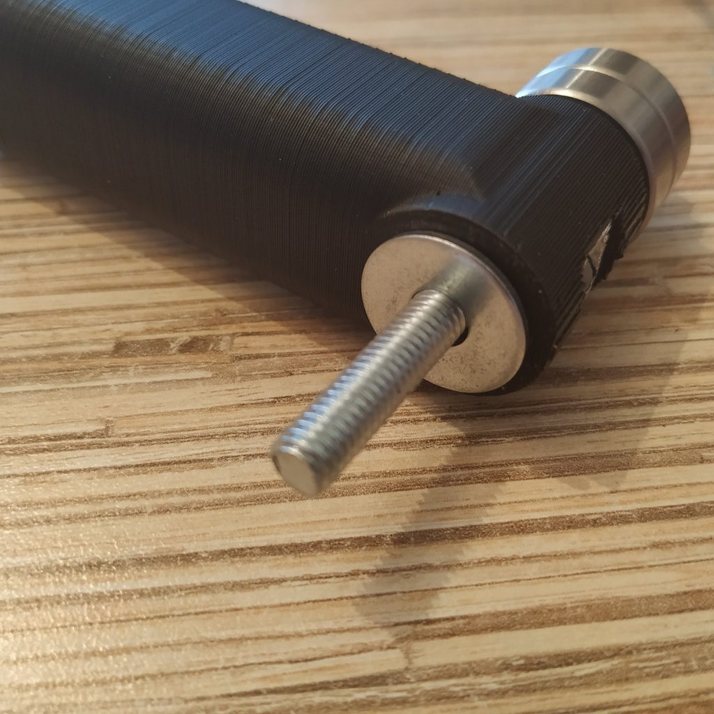
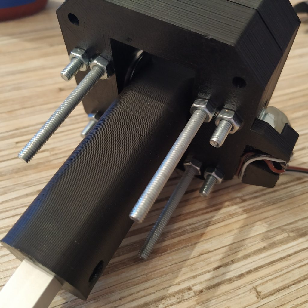
19. Insert 4 M4x70mm screws into the frame as shown on the picture below, add nuts, use thread locker.
20. Put the curtain part on and fix it with 2 M4x40mm screws, add nuts, use thread locker. The axis assembly is finished!
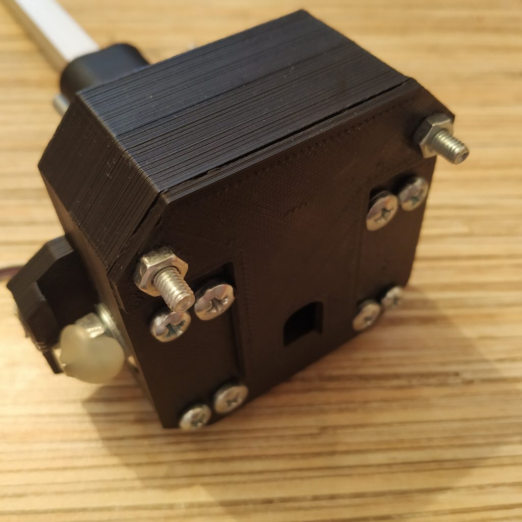
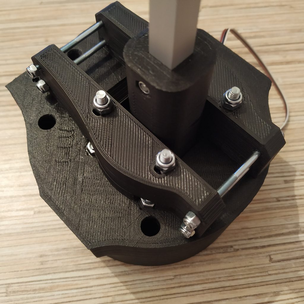
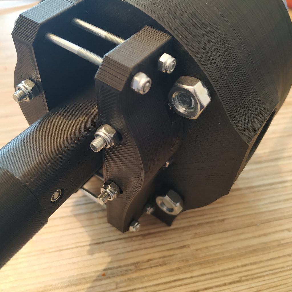
21. Insert axis assembly into the housing. Fix with nuts, use thread locker.
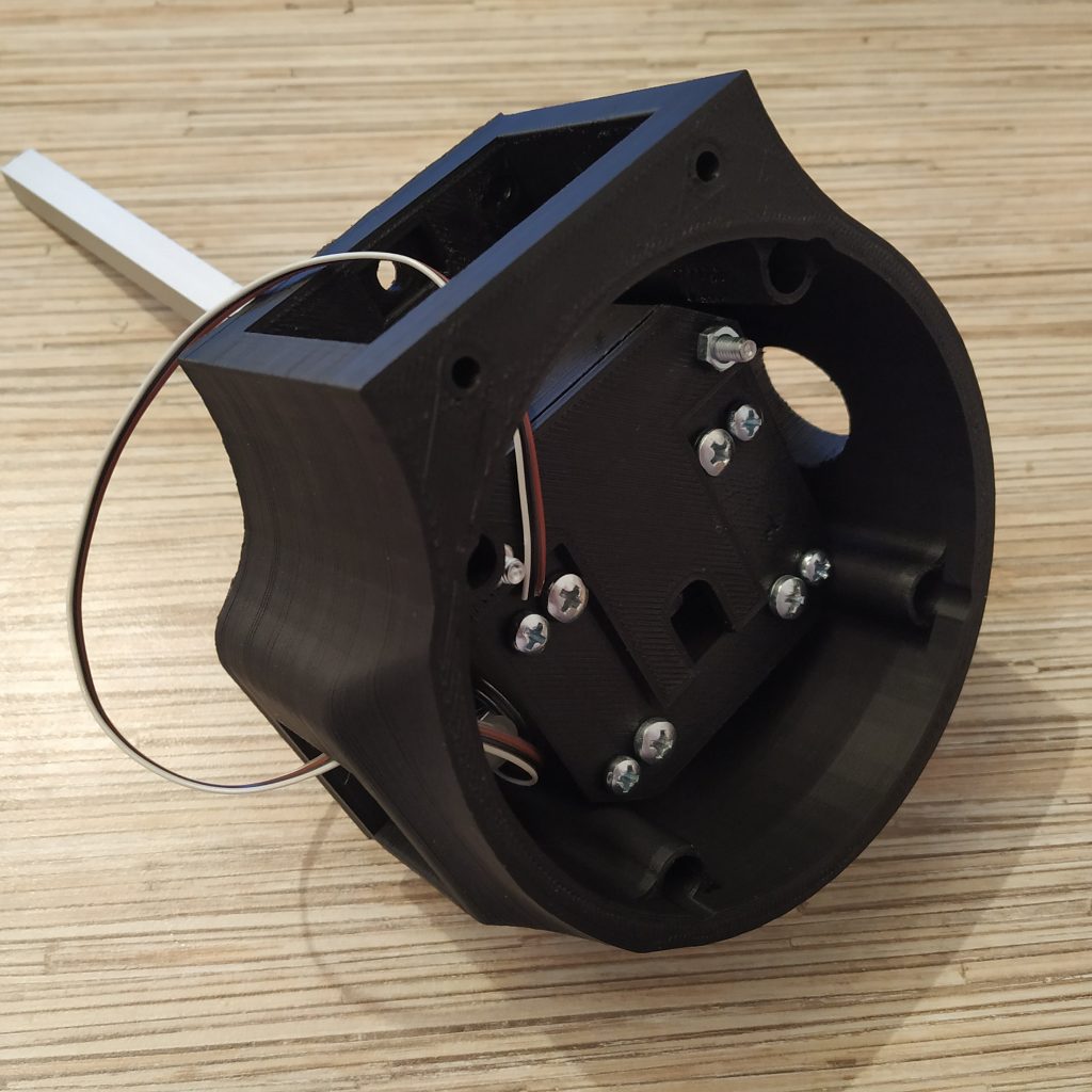
22. Put the friction tensioner together. To do it, widen holes in its left part with a PH0 3mm screwdriver or a drill, and insert 4 M3x50mm screws into it. After that, connect the right part of the tensioner and put nyloc nuts on. Do not tighten too much.
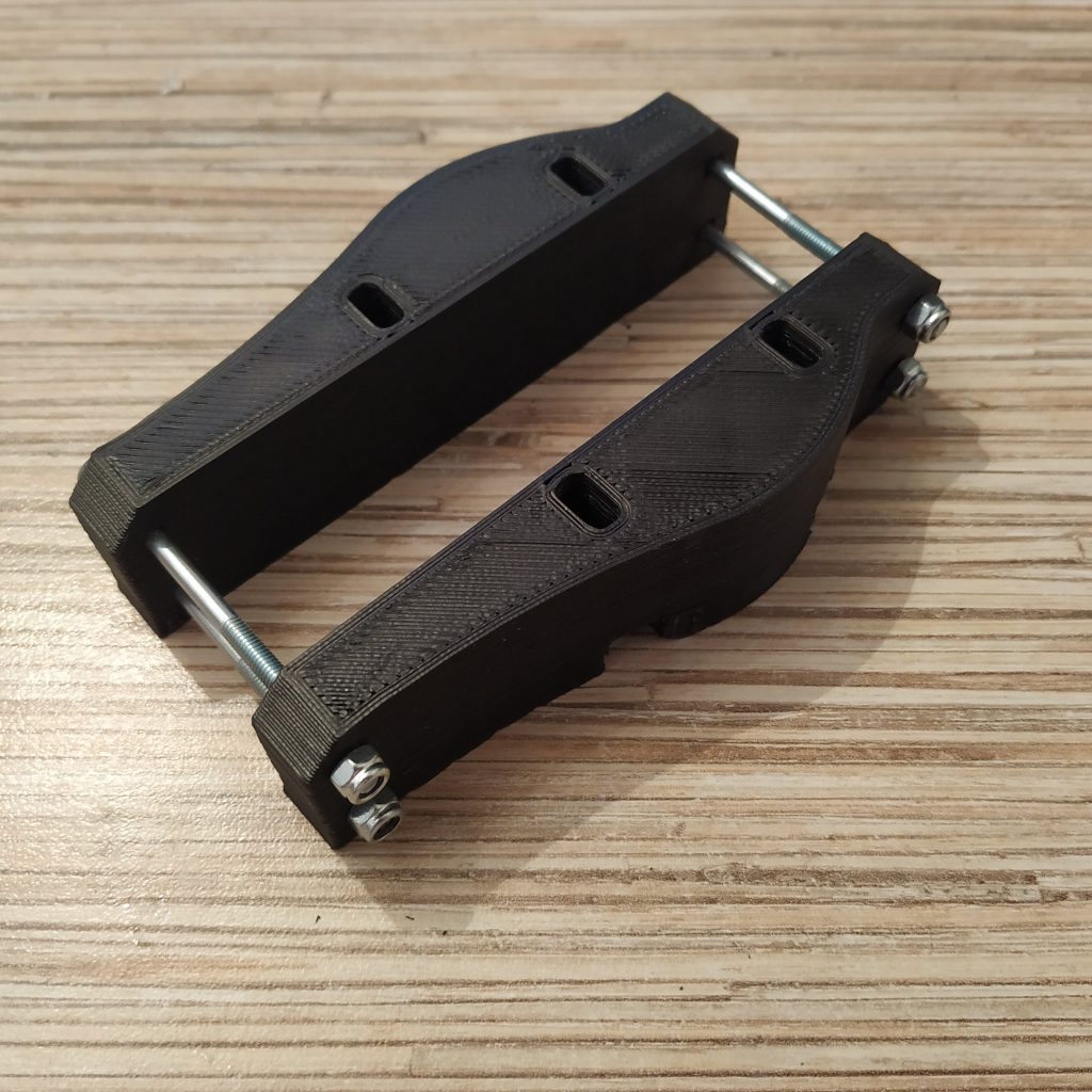
23. Attach the tensioner to the lever housing. Add and tighten 4 M4 nuts so there will be some clearance between them and the tensioner.
23. Time to connect and assemble your chosen lever body. Follow the corresponding manual and route wires through the lever as described in it.
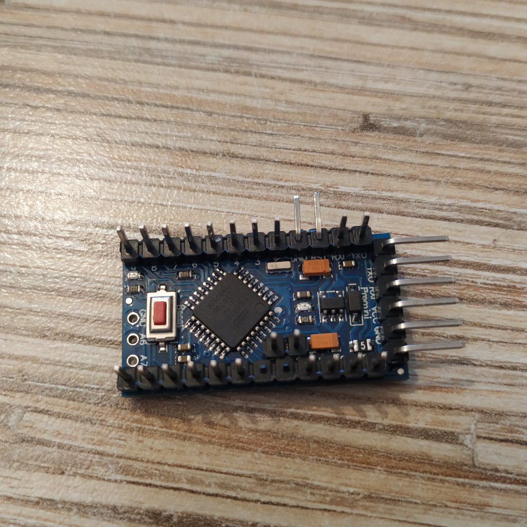
24. Remove 2 pins (A2,A3) from the header. Only remove A3 if you will be making a twin lever.
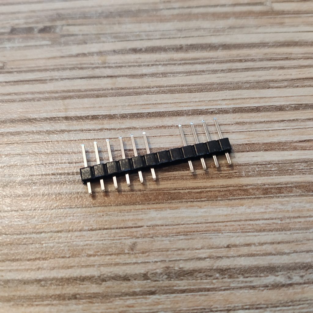
25. Solder headers to the Pro Mini board. Wash the board after that with something like Fairy. Use neutral flux! If you’re short of pins, just use some spare ones to populate A4 and A5, like ones from pins 8 and 9 of Pro Mini.
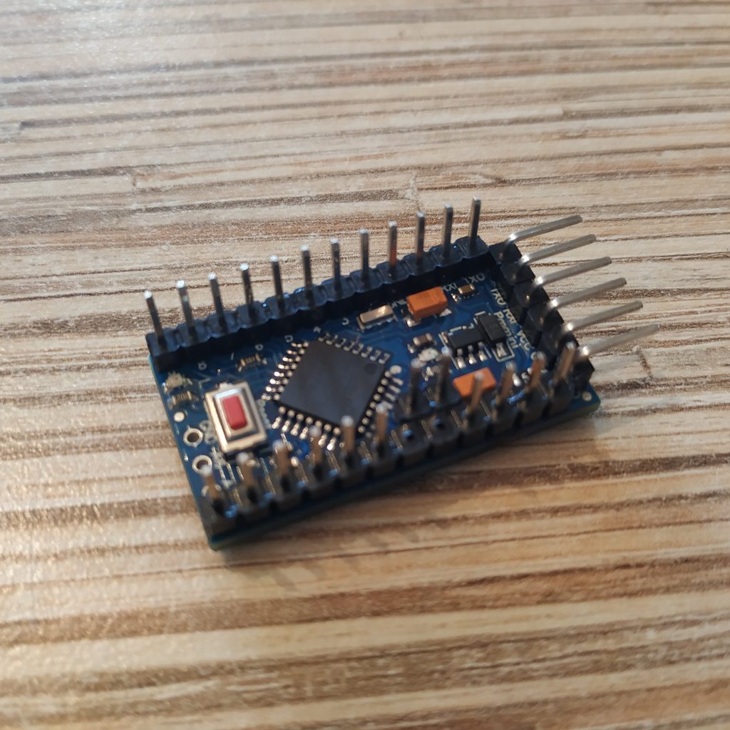
26. Bend RST and GND pins as shown on the picture:
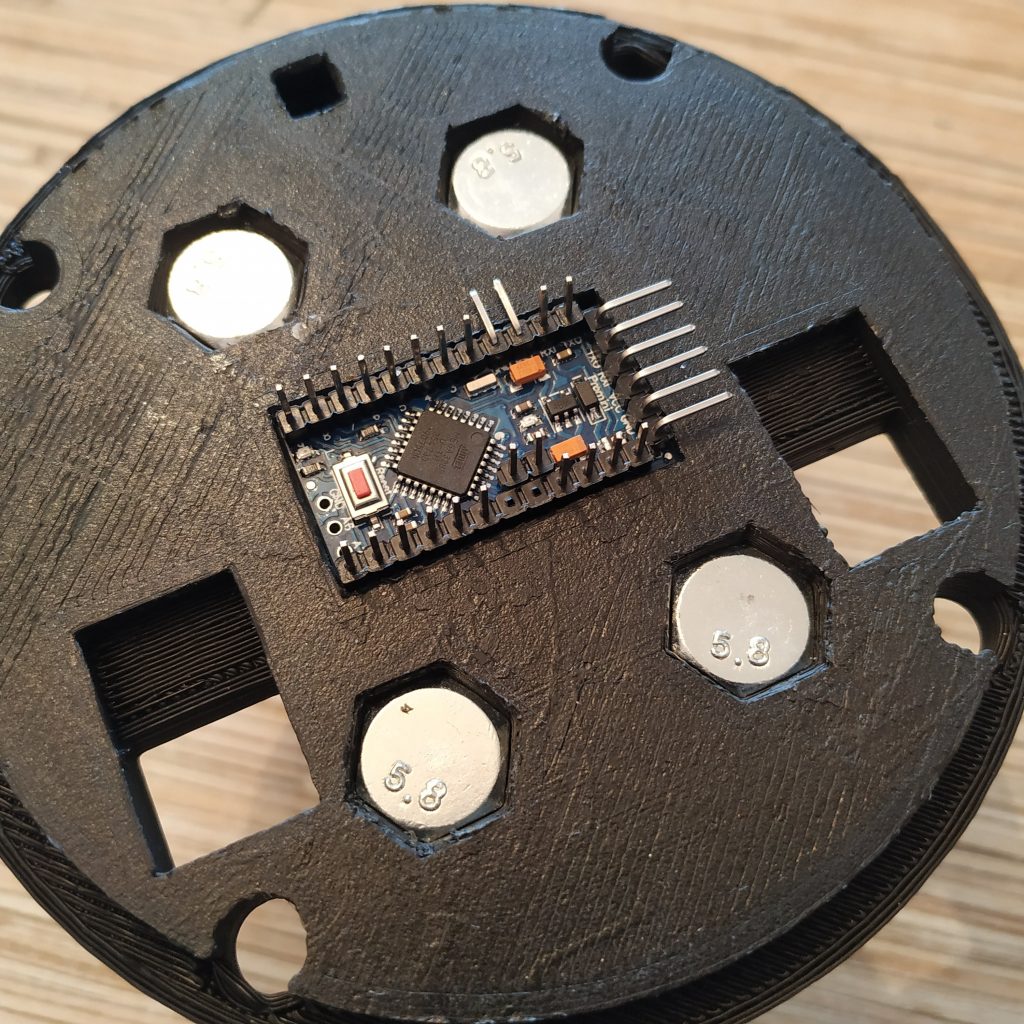
27. Put the board into its socket in the lid. Bend reset pins should point towards the button socket in the lid.
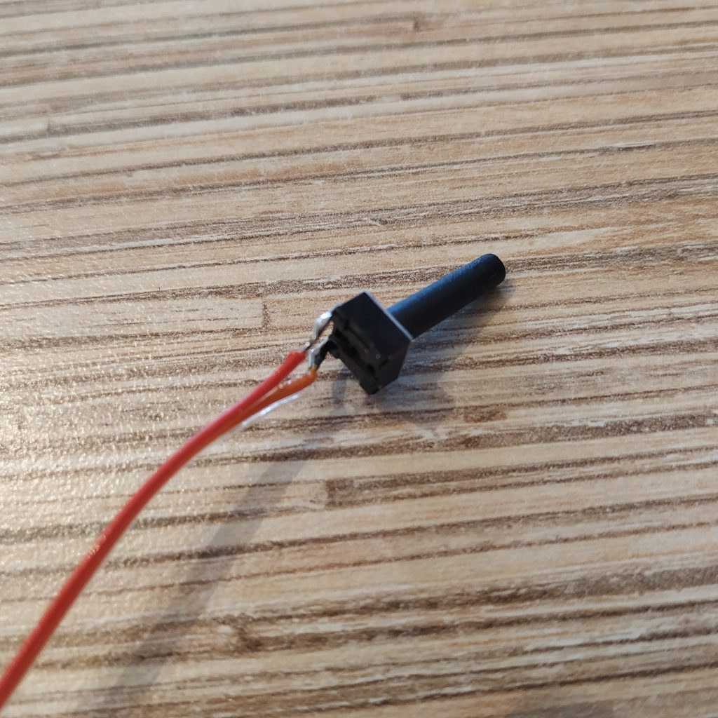
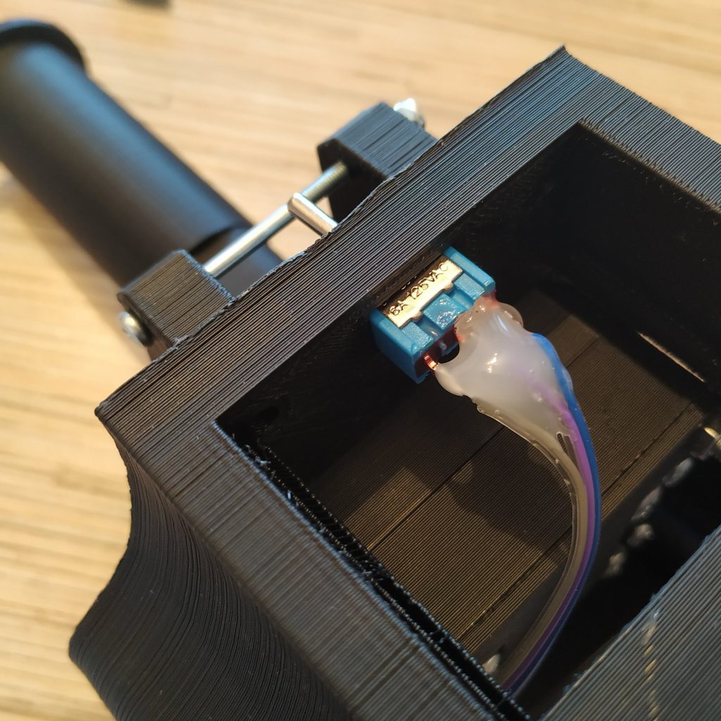
28. Solder wires to a 17mm button. Break unused pins off. Press-fit the button into its socket, secure with hot glue.
29. Solder 7-wire cables to 2 Ethernet sockets, and press-fit them into the lid.
30. Solder wires from pins 5,6,7 of sockets to Rx, Tx, DTR pins of the board. Cable management will help a lot!
31. Add one more piece of 4-wire i2c cable and make an I2C cable tie. Don’t forget to add an I2C cable for the head if needed!
32. Connect I2C cable to VCC,GND,SCL(A5),SDA(A4)
33. Connect the left wire of the mode switch to pin 2, right one to pin 3, middle one to GND next to RST pin.
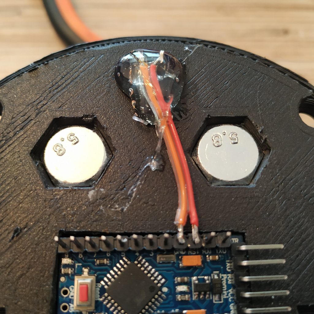
34. Solder SS495A1 cable to A0, VCC and GND to VCC and GND on the UART header. Connect throttle pot to A1, VCC and GND if one is present.
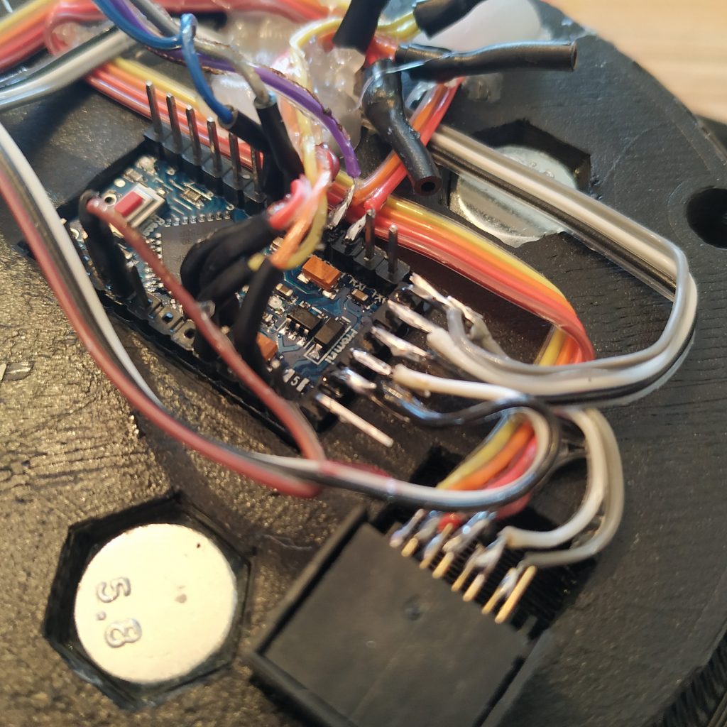
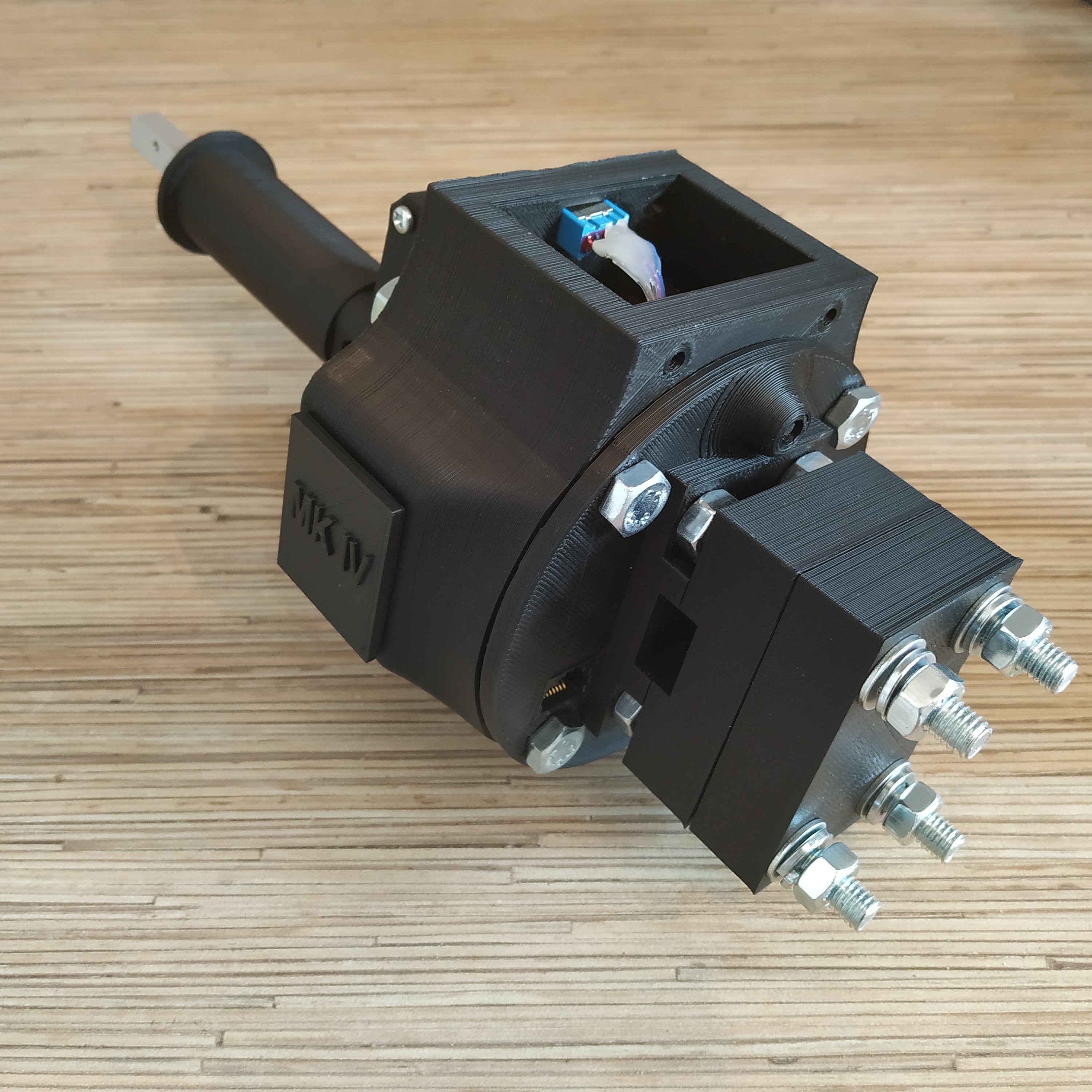
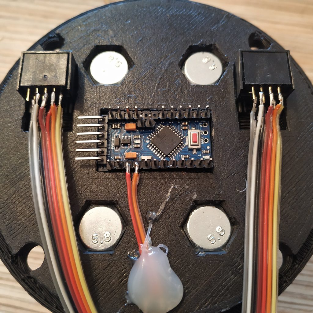
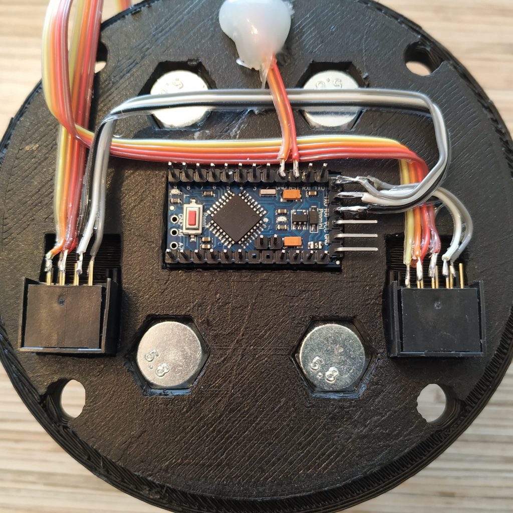
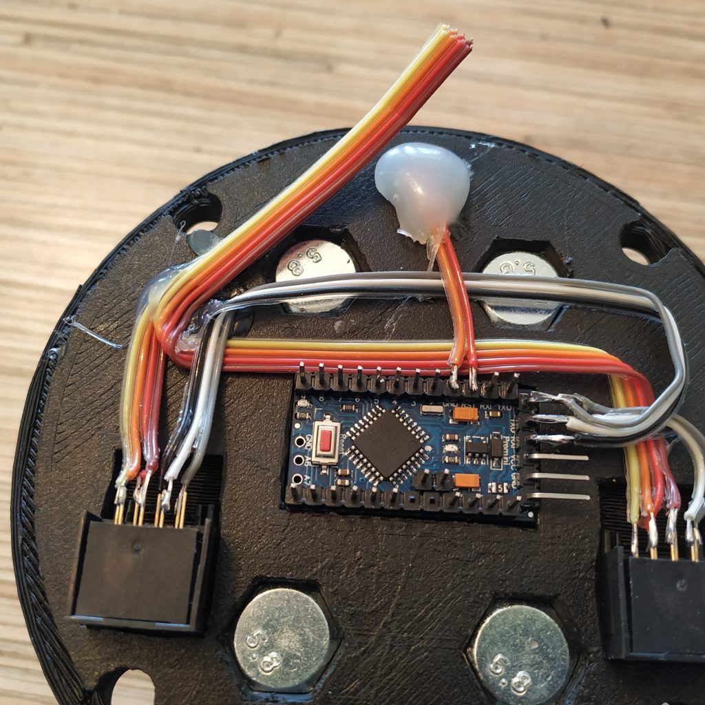
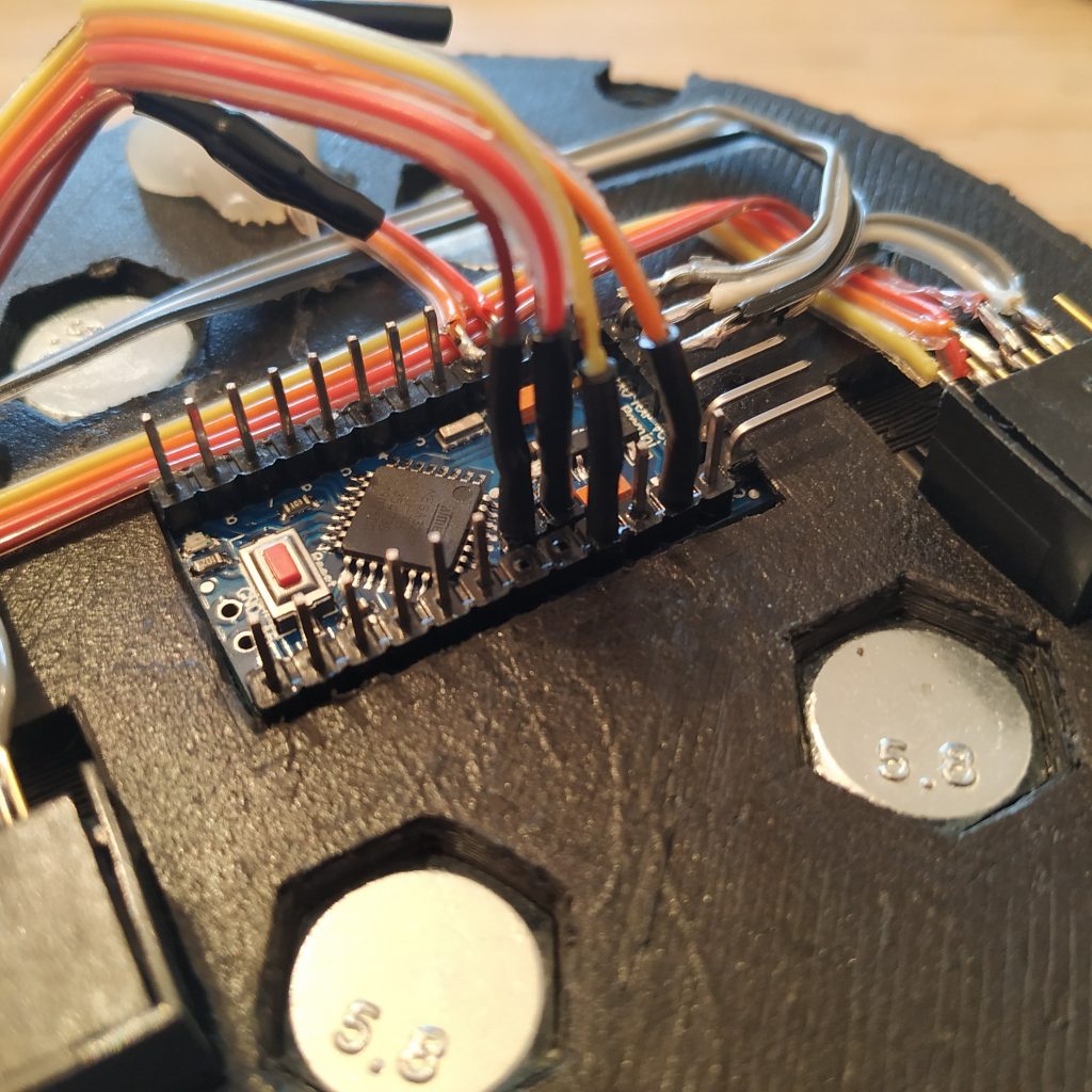
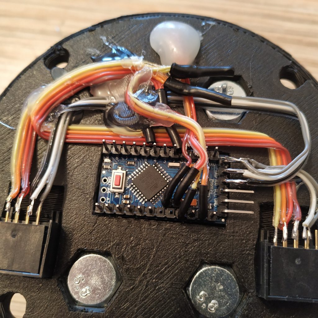
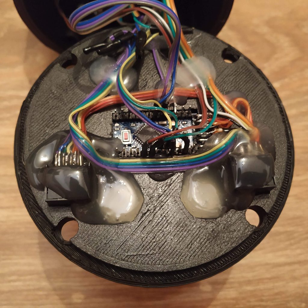
24. Here’s how the assembly should look:
- Mode switch left pin -> Pro Mini pin 2
- Mode switch GND -> GND next to RST
- Mode switch right pin -> Pro Mini pin 3
- MCU RST button -> between RST and GND next to it
- SS495A1 pin 1 -> THR POT left pin (on the left when the lever is mounted as usual) VCC cable tie <- Pro Mini VCC <- Ethernet sockets pin 1
- SS495A1 pin 2 -> THR POT right pin -> GND cable tie <- Pro Mini GND <- Ethernet sockets pin 2
- A0 -> SS495A1 signal
- A1 -> THR POT signal
- A4 -> SDA cable tie <- Ethernet sockets pin 3
- A5 -> SCL cable tie <- Ethernet sockets pin 4
- Collective head I2C cable -> VCC, GND, SCL
,SDA cable ties - Pro Mini Rx -> Ethernet sockets pin 5
- Pro Mini Tx -> Ethernet sockets pin 6
- Pro Mini DTR -> Ethernet sockets pin 7
If everything looks correct, flash the board with its firmware using FT232TL based adapter (or any other) and a UART- Ethernet cable connected as follows:
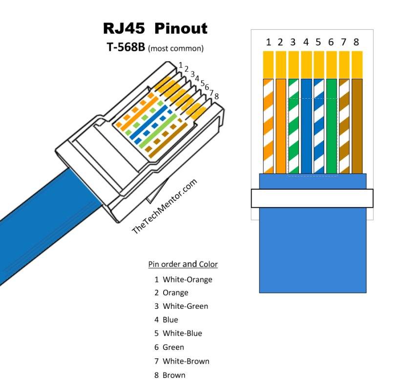
WHITE-ORANGE -> VCC
ORANGE -> GND
WHITE-GREEN -> NC
BLUE -> NC
WHITE-BLUE -> USB-UART TX
GREEN -> USB-UART RX
WHITE-BROWN -> USB-UART DTR (if available)
BROWN -> NC
We will need to calibrate the lever now. To do it, uncomment
#define CALIBRATE
and comment out map functions:
//z = map(z,0,936,0,1023);
//rz = map(rz,32,1023,1023,0);
Then, flash the firmware and look into serial output. Adjust the bolt of the axis until the “zero” position of the lever will correspond to 0 in serial output. Check that the range you’re getting is close to 0-1000.
Replace 1st 2 values in map functions with values you see. Uncomment these functions and comment out the CALIBRATE line. Reflash the firmware, check there’s no serial output, and that’s it.
25. After finishing with assembling of the lever body, put the lid onto the housing. Fix with 4 M8x70 or M8x75mm bolts and nuts.
26. Add remaining parts of the housing: pneumatics mount and side covers. Congratulations, the base is finished!


Hi again 🙂
This Hall effect sensor is the one that can fit?
https://www.aliexpress.com/item/32909898345.html?spm=a2g0o.productlist.0.0.7e492672ODqwkn&algo_pvid=93d94640-2791-4d24-8341-59de8082cffe&algo_expid=93d94640-2791-4d24-8341-59de8082cffe-4&btsid=51aedb4b-6aab-4eef-b46c-8d721a8c6dde&ws_ab_test=searchweb0_0,searchweb201602_5,searchweb201603_53
Hi! Yup, looks correct!
Hi again 🙂
I cant see the switch in par 33 on the Components.
Can u please tell me the right model I need?
Also, I can’t find the 6K1 10KOhm LINEAR rotary potentiometer use on the manual.
Hi again 🙂
I cant see the switch in par 33 on the Components.
Can u please tell me the right model I need?
Also, I can’t find the 6K1 10KOhm LINEAR rotary potentiometer use on the manual.
Also, I can’t find on Ebay and Aliexpress the 2 x M6x18x8mm hubs and the TJ8P8C sockets
Can u help me find them?
Hi! =) Fixed it. The switch is an M-103 3-way ON-OFF-ON one.
Sockets, you can find e.g. here:
https://bit.ly/2L5npOd
For cylinders, you can either use a plastic part, buy a longer piece on aliexpress (look for “round coupler nut” or smth like that) and simply saw it off, or buy them from me, along with 6x6x4mm magnets and cyclic springs if you need them (if you like to support the project).
The pot is for throttle axis, it should probably be in the body manual, but there’s no one yet, so
I guess I’ll leave it here for a while =)
MKIV single throttle lever requires a 200mm piece of aluminum square pipe.
Thanks !!!!
I will love to support this project
Ease tell me how much will cost to ship to israel.
The magnets
The hub
And the springs ( i can get them in israel but like to support your work)
Also if i get it right ,
For this build i not need the pot. I need it only when i build the UH-1 throttle?
So i need only 1 right ?
Thanks again
Sorry for all my question i just collect all the parts i need for this project before i start.
I make a fully buying list with all the screw and electric and so.
For now i am at 55$.
I plan for start to build the :
Master controller MKIV.
MKIV collective base.
UH-1 collective head.
When finish this 3 parts i will go to next step and do the cyclic base and uh-1 cyclic.
Thanks for your great job and for your support in crazy people like us 🙂
You’re welcome! Happy to hear you want to support the project! You only need 1 pot for the throttle grip. Don’t forget the pneumatic mod – it feels great!
Will check prices for the stuff and shipping and write an email to you.
Hello, an awesome project!
I would like to ask you a question, I am making a collective and I have used a hall sensor (Allegro A1324 5000 mV / G) and as the bus only rotates 30 0 40º I only get half of the sensor travel (half axis) being impossible to use in the simulator
How did you solve this without gears?