Summary
It is a fully operational Simchair MKIII compatible remix of a very nice B8 flight stick replica, originally by schrodingers_cat. It is designed for use with a new i2c controller. It contains an Arduino Pro Micro inside (sketch included). The trigger has two positions: half-press (intercom) and full-press with a click (radio push to talk). When the trigger is fully pressed, a half-press button is disabled by the software, so your sim will see these two positions as entirely separate buttons.
Components
You will need:
1 x Arduino pro mini board
1 x KY-023 joystick module
1 x USBtoCOM adapter (e.g., PL2303) or another Arduino to program it
3 x PBS-11B buttons
1 x PBS-10B-2 button (trigger intercom)
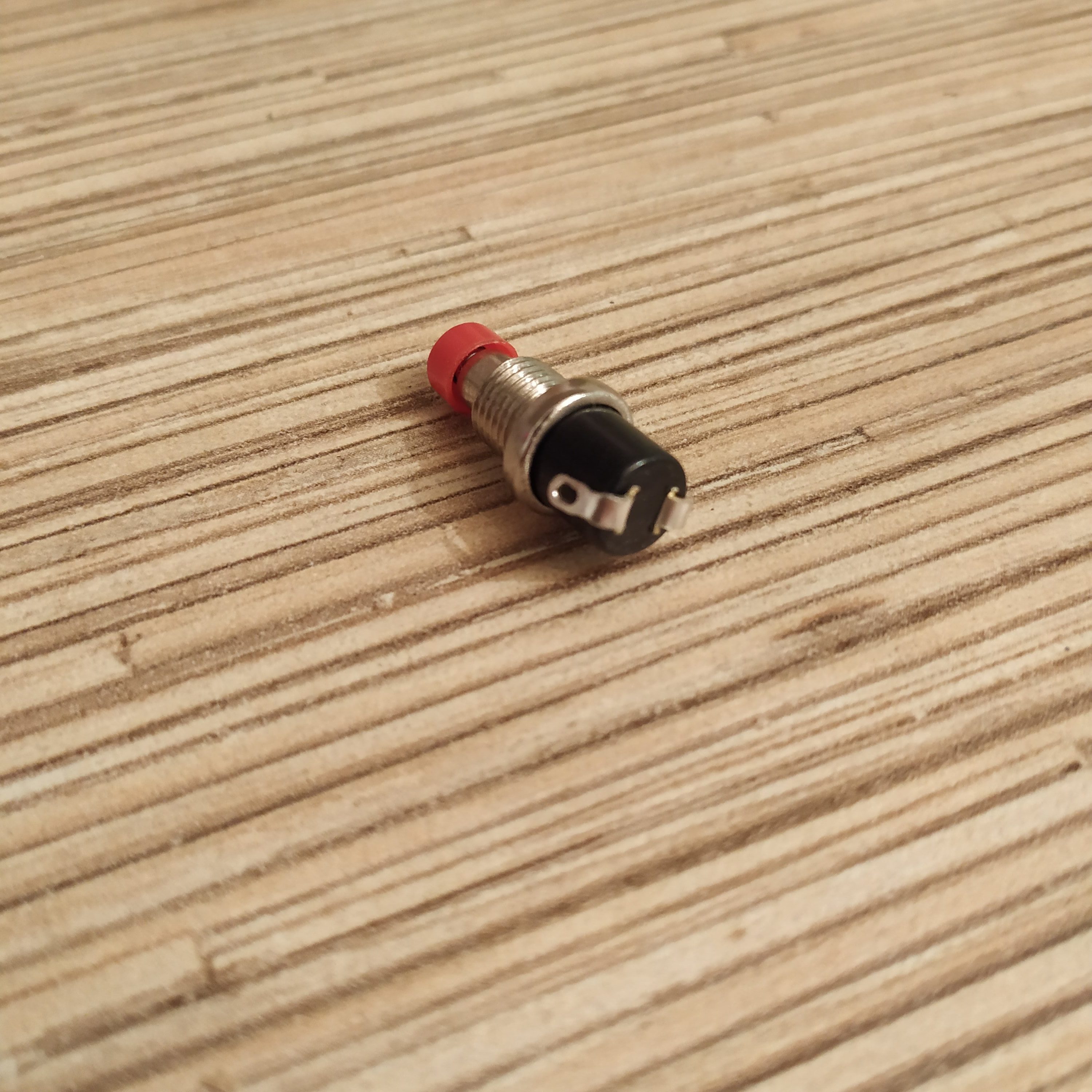
1 x 12x12x4.3mm TS-1202 button (https://goo.gl/mjpt6T) (trigger PTT)
some wires
1 x m8 x 60 bolt and nut
1m of UTP-5e cable
1m of 10mm aluminum square pipe
6 x m3x20 screws and nuts
1 x m3x40 screw for trigger mounting
1 x Simchair MKIII I2C controller (Arduino Leonardo based) (https://www.thingiverse.com/thing:2919692)
1 x Simchair MKIII cyclic gimbal V2 (https://www.thingiverse.com/thing:2917209)
Hot glue gun
Available mods
none
Special features
- hot plug support- you can detach and re-attach stick mid-flight
- sensitivity switching with hat switch button (extreme precision mode)
- force trim toggle button (the top one by default), emergency trim release (with a hat switch button click)
- 2-way realistic intercom/push to talk switch, half-press toggles intercom, full-press (click) toggless push-to-talk
- ‘push-to-talk sends a keyboard key’ option, handy if your external radio work through teamspeak
- hat switch can be used to make precise adjustments to the cyclic position while trimmed, or as a regular hat switch
Downloads
Assembly
The assembly pretty much consists of joining the halves together, when finished with electronics, and putting a trigger on after that. At first, we need to solder wires to PBS-11B buttons and insert them into their sockets. Bend their legs as shown on the picture below, then solder wires to the innermost areas of contacts (so wires wont be damaged when you will be inserting the button into its socket):
To fit the KY-023 module into the stick, we need to cut off its upper left corner (no worries, there’s nothing useful there :D).
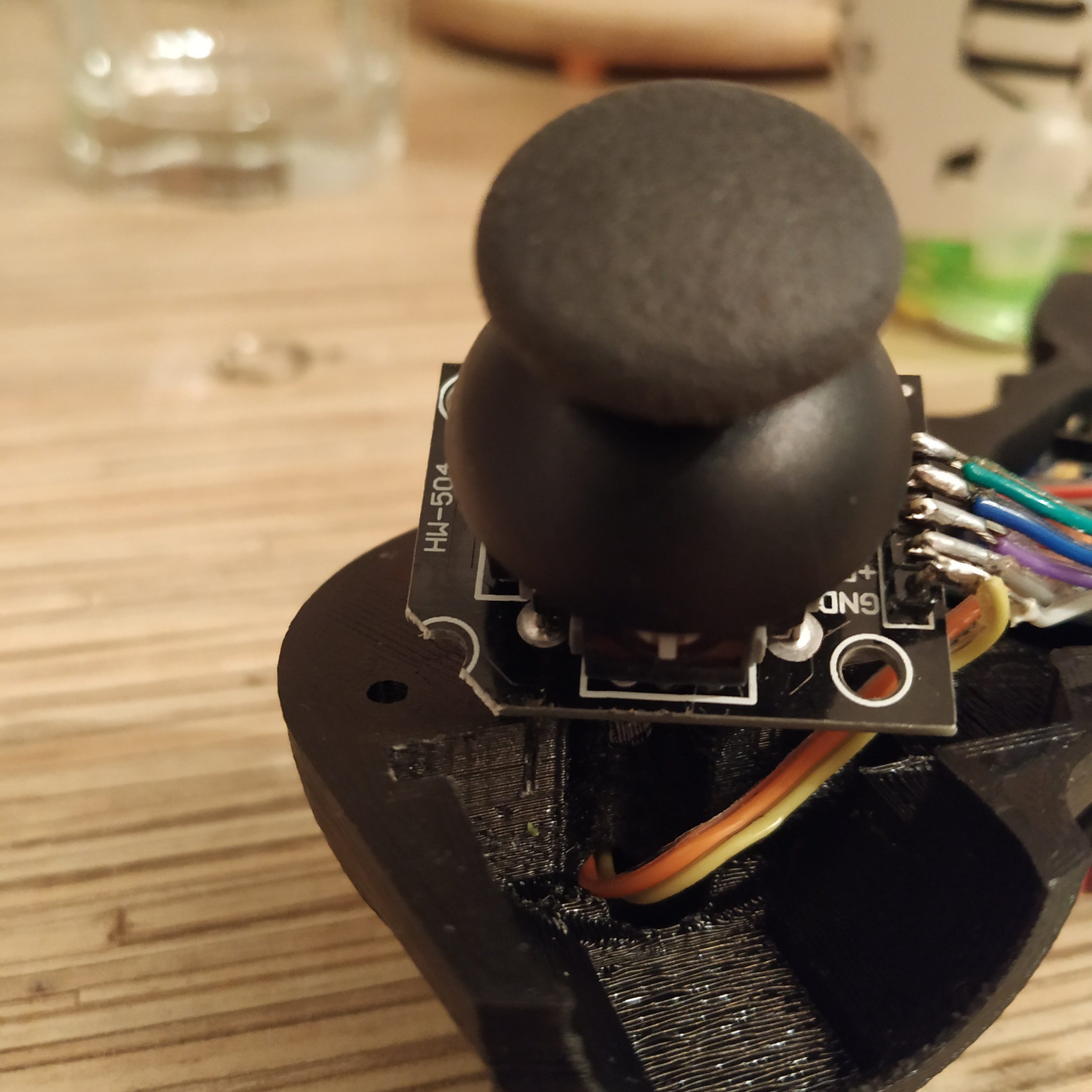
Connect everything as shown in “Electronics” section below. Here’s how the result should look like:
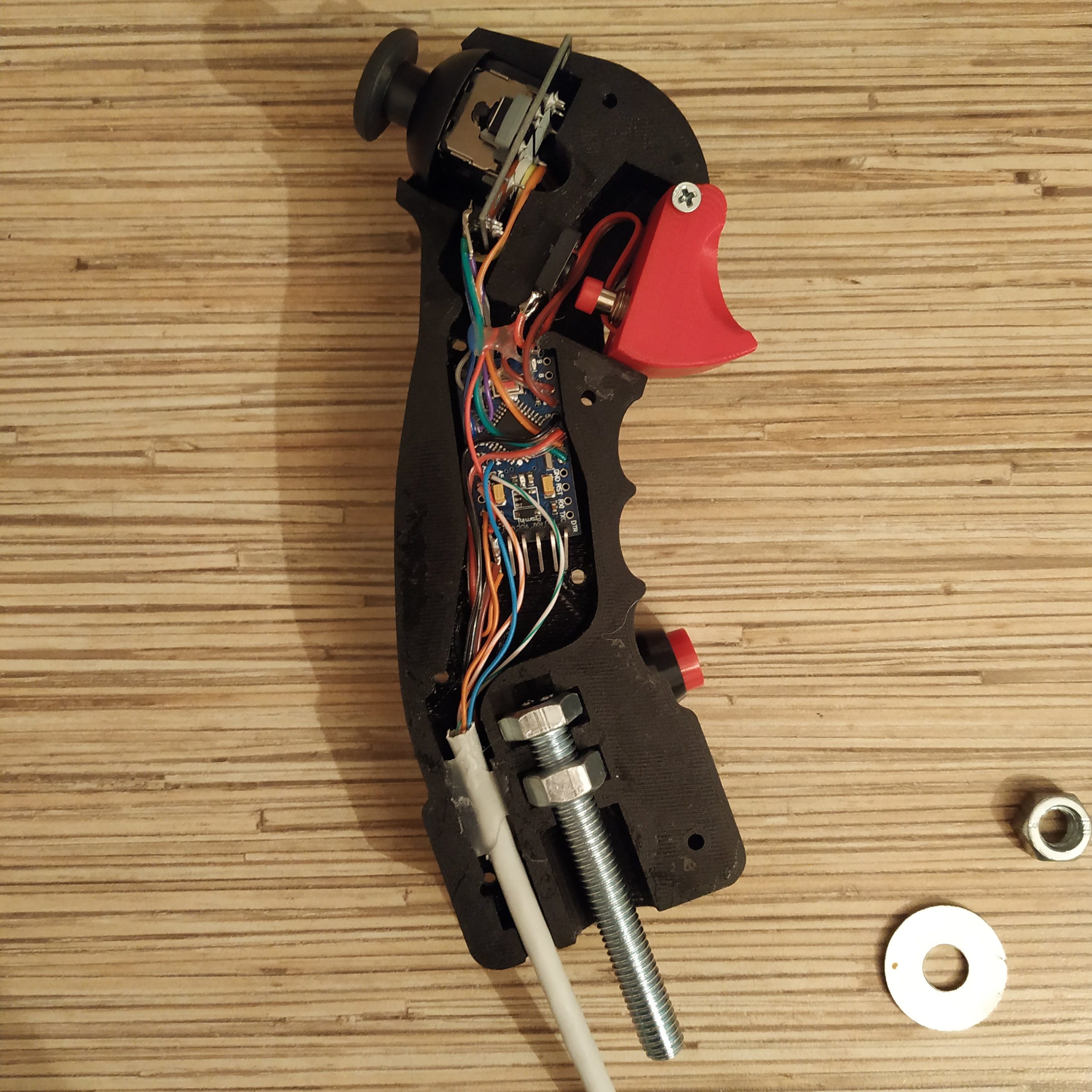
PTT TS-1202 button is glued with hot glue to the left half part just under the PBS-10B2 tip, which goes into the trigger (adjust its position so the PBS-10 button tip will push to the center of it). Fix wires with hot glue (make sure screw holes are not covered with wires!), add some glue to an ethernet cable. After joining halves of the stick together and tightening (be gentle!) screws, attach a trigger with m3x40mm screw. Insert the screw to around 80%, add a small drop of hot glue to fix it in place, insert it fully, wipe any leftover glue with a paper towel (use a knife if needed, hot glue can be removed easily). Put an M8 washer and a nut on a bolt that protrudes from the bottom of a stick.
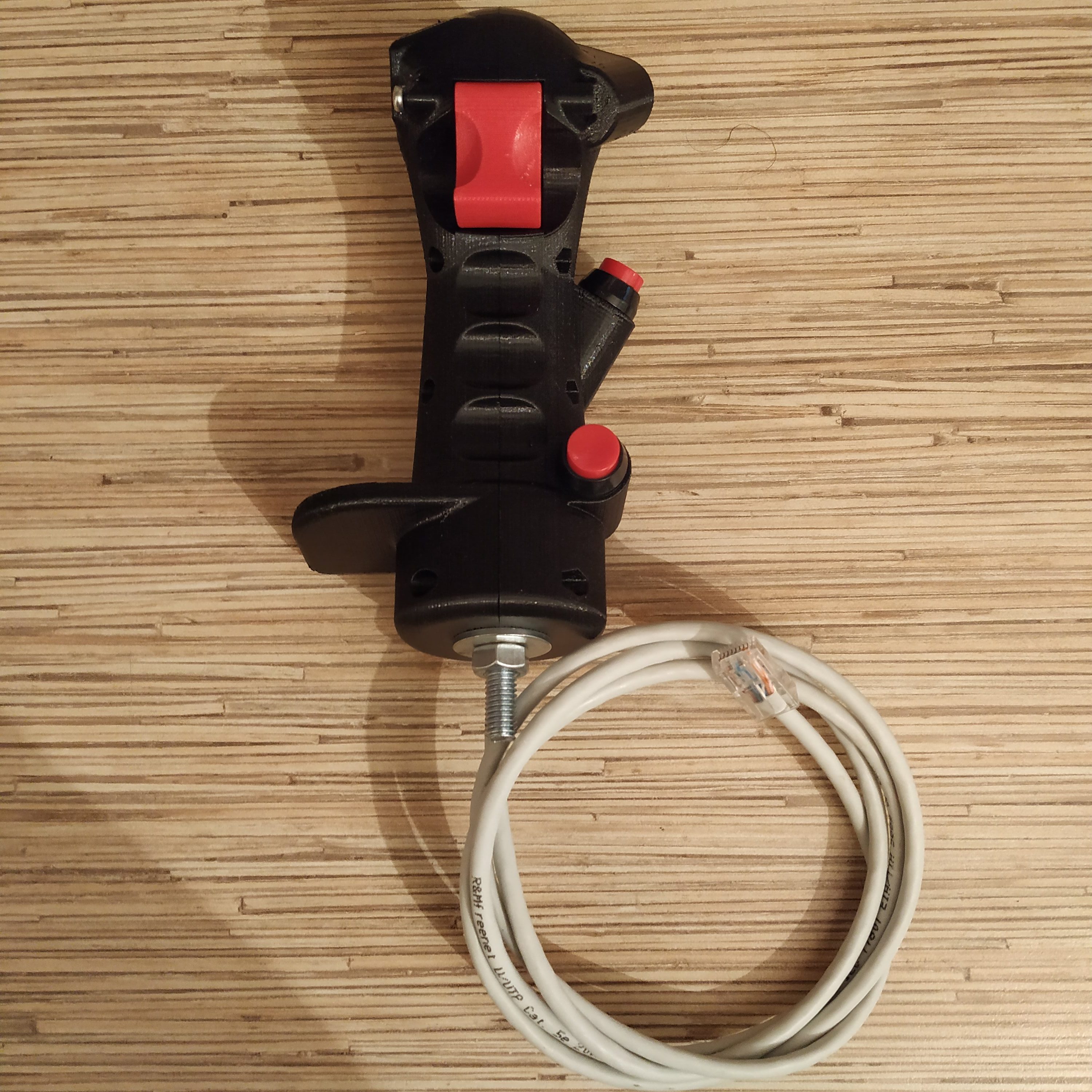
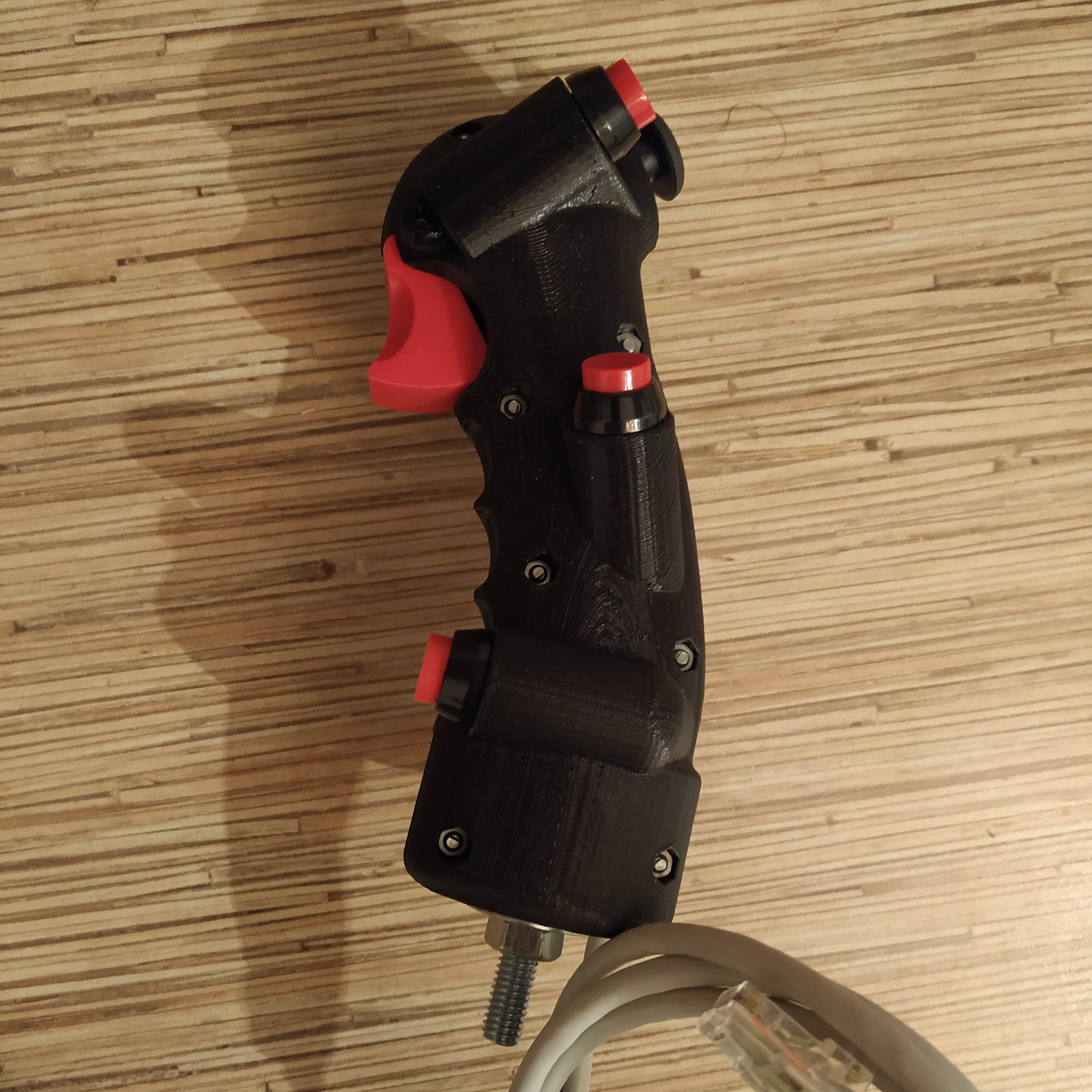
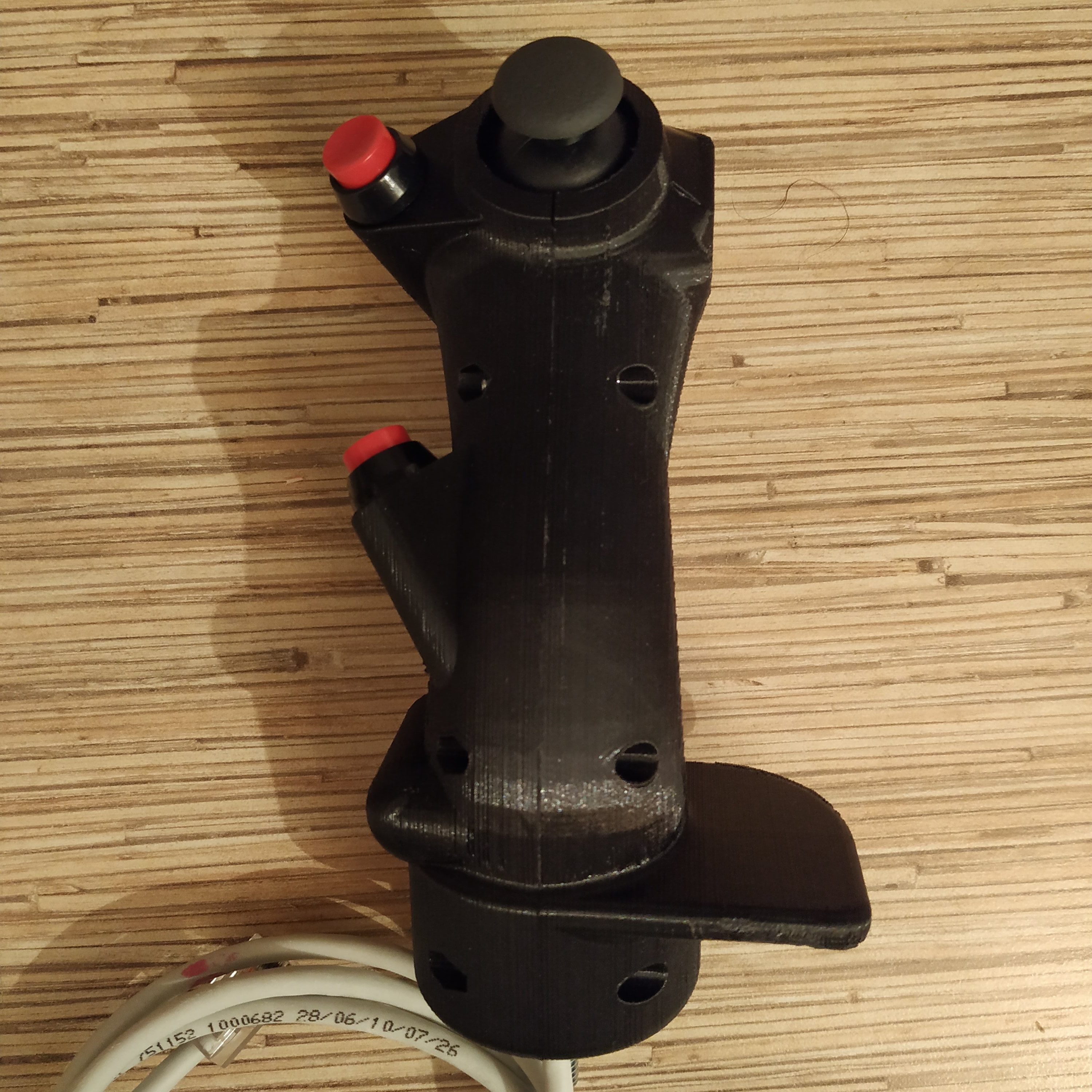
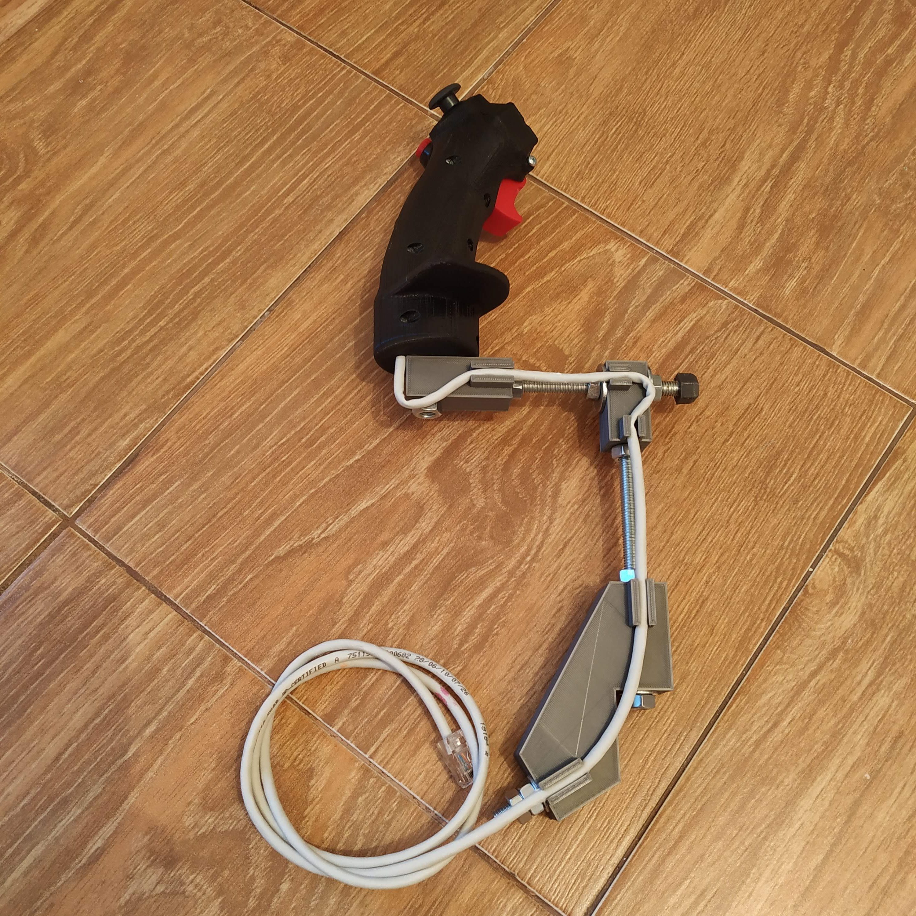
Adjust stick height to your liking, cut the aluminum pipe accordingly, then route an ethernet cable through the pipe and crimp it as a regular ethernet cable.
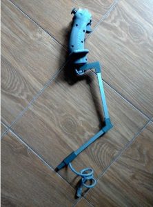
Here’s how assembled stick looks:
Choosing a stick frame (IKEA GUNDE chair)
After the stick grip is assembled, it’s time to choose a stick frame for it. There are two options: bolt-on ergonomic, adjustable stick, or a light detachable one. 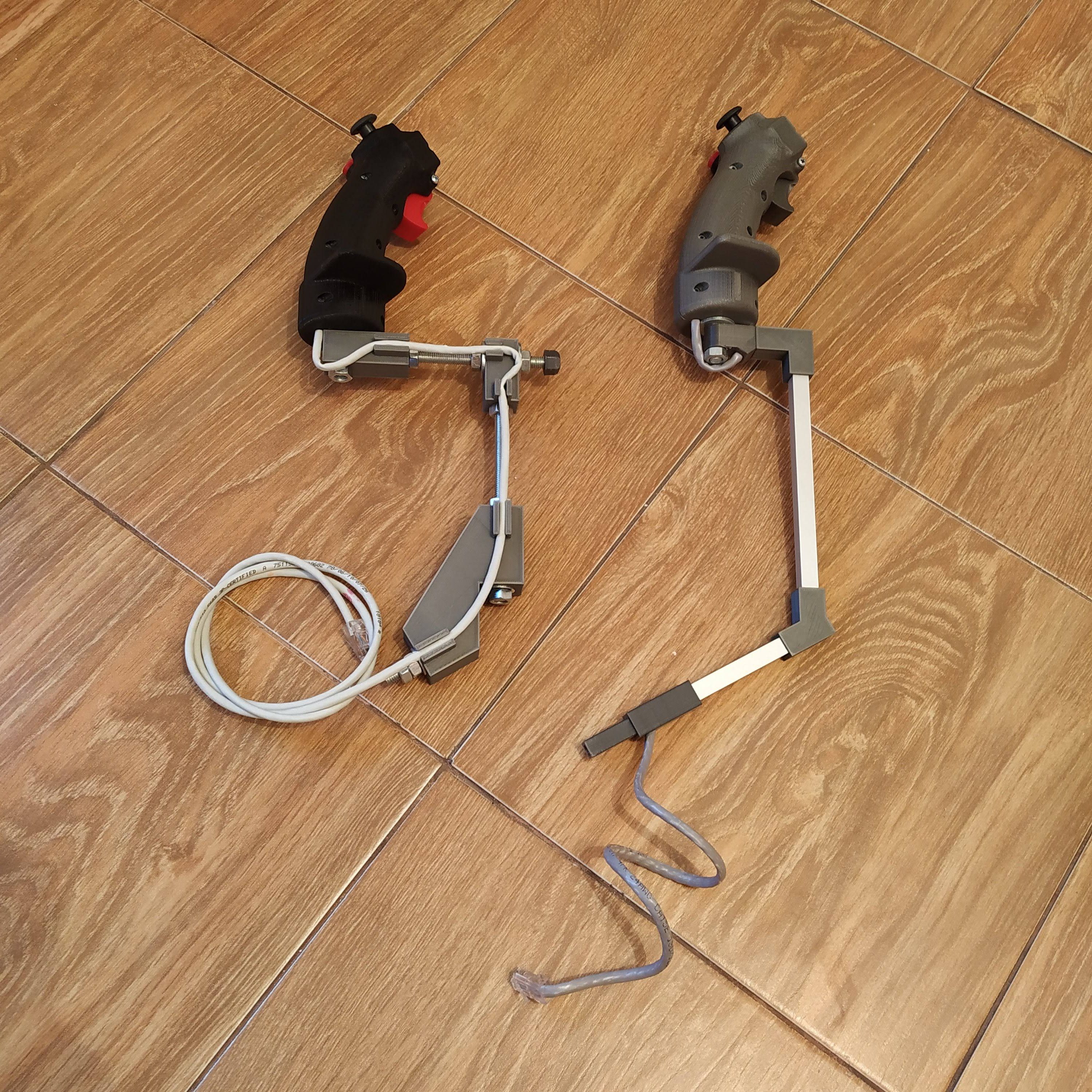
The main difference between them is, that bolt-on variant suits better for a spring loaded cyclic, while the detachable version is better with a non-centered one. Both variants are perfectly flyable with either version of cyclic gimbal though , so the only thing to decide is whether you need to be able to remove the lever by simply pulling it from its socket, or you can live with a thought you have to use 2 wrenches to attach or detach it.

Alternatively, you can just mount your cyclic gimbal to the floor and use a 8mm threaded rod to connect the stick grip.
Electronics
Connect buttons and the pot board to an Arduino as follows:
POT BOARD VCC to PIN 10
POT BOARD GND -> Arduino GND
POT VRx -> A0
POT VRy -> A1
POT BOARD BUTTON – PIN 2
TOP (TRIMMER) – between PIN 3 and GND
MIDDLE (FIRE) – between PIN 4 and GND
BOTTOM – between PIN 5 and GND
TRIGGER INTERCOM – between PIN 6 and GND
TRIGGER PTT (full press) – between PIN 7 and GND
A4 (SDA) -> ethernet cable blue wire
A5 (SCL) -> ethernet cable green-white wire
VCC -> ethernet cable orange-white wire
GND -> ethernet cable orange wire
After soldering everything, put the Pro mini board into its socket, organize wires, put an M8x75 bolt with a nut into its place, and finally screw the halves together.
Downloads
Simchair MKIII I2C latest software on GitHub
Hi Alexey – just assembling the flight stick. Unclear for me is how the KY-023 is connected to the Arduino. The KY-023 has GND and +5V as inputs and as outputs VRX, VRY and SW. According to your description SW to PIN2 ( which is D2 ? ) , but what dou you mean with “POT BOARD VCC to PIN 10” ? Do you mean VRY to PIN10 ( A10? ) ? Is VRX not used?
Guido
Hi Guido! You can just connect the pot board (KY-023) VCC and GND together with other 5v and GND wires respectively, or you can connect its VCC to digital pin 10 (it’s set to HIGH which is 5v in firmware). PIN2 means D2, PIN3 means D3 etc. VRx goes to A0, VRy goes to A1 =) Missed it somehow in the manual, will fix, ty for noticing it!
Many thanks!
Guido
Hi Alexey – I am putting together a flight stick and I’m having trouble getting pin 3 to work on the pro mini (Top trimmer). I have tried it on 2 different minis and getting the exact same thing; not registering in the joystick configuration. All other buttons and axes are working perfectly. I looked at the code for b8_stick and didn’t notice anything out of the ordinary. Just wondering if there is something I might be missing? Thanks for any help you can provide.
Also have built the cyclic gimbal and am still looking for appropriate springs. Just wondering if anyone has sourced a good spring alternative in Canada.
I found some springs at the TSC store in ontario canada – they look like they may be perfect! They have a whole section of springs in their store for farm equipment.
I’d love to hear how your build is going and where you sourced parts! (also in Canada!)
Get a hold of me at telemole@gmail.com or by following my name’s link! thanks!
Hi! This is intentional because of the nature of how the trim works! It is incompatible with joystick button function, so it doesn’t register in joy.cpl!
You can check that it works by either Serial.print’ing its value, or just by looking at the axis cross -it will freeze when the button is pressed and will only unlock when the stick is returned to its physical center (spring loaded cyclic force trim mode) or when the trim button is pressed again and the stick will be back within force trim disengage radius from the trimmed position (springless cyclic adaptive force trim mode).
To make it work as a joystick button, you can also disable force trim completely.
I have to write more about it definitely, as it’s not only a major feature but also flying with springs and not using it won’t be realistic! Will try doing it tomorrow.
Cheers!
Great thanks!! Got it working now; pretty cool feature that I wasn’t expecting. I’m curious if the thumbstick has something to do with trim as well. It doesn’t seem to register as x and y axes or any of the sliders in the joystick config. Thanks.
The thumbstick is used to switch between sensitivity settings (100% and 80% by default), also 2 clicks reset the trim position (emergency trim release, only use it as a last resort if you can’t unlock controls as it will cause a sudden attitude change that may over G the airframe).
80% sensitivity setting is good for flying 407 in X-plane, 100% is better for smth like 206 or 412 =) Note that 80% will map your sensor range to a reduced axis range thus limiting your controls travel to 80% of axis range, but axes will stay linear. That’s fine with almost any helicopter (but sometimes can be a problem in DCS Huey if you want to fly very fast). Anyway, it’s a nice addition to curves (in fact, is better than curves for helicopters as the stick is never centered) that are present in any sim, and an ability to switch modes with a button is quite handy =)
Hello Alexey!
I am considering to build the simchair and am currently looking for where to buy the necessary parts.
Is this the correct spring for the stick-centering mechanism?
https://www.lada.shop/en/2101-3504094.html
It says it is for the lada 2101 brake pedal, however I cannot find one for the clutch pedal (could it be the same part?). Do you know the exact part number?
Thanks,
Maximilian
Hi! The brake pedal spring will be way too strong. The part number ot the clutch pedal spring should be 2101-1602094. It seems like it’s also used on Chevrolet Niva, maybe Lada 4×4 as well (not sure about the latter though). If you wont be able to find it, let me know, I can buy it here for you and ship to your location. Shouldn’t be too expensive considering its weight =)
Theoretically, any other similar spring should be fine, it just shouldn’t be too stiff.
Spring dimensions:
1,2mm thick, 11,5mm diameter, 53,7mm height without hooks, ~81mm with hooks when squeezed
Cheers!
It would be great if you could send me the springs 🙂
Please send me an email with the price (shipping to austria), and I can send you my address.
Thanks!
Sent an email =)
Hi Alexey!
I have started to print te first parts and to assemble the B8 grip.
I just had a little problem with the small space inside the grip, I could not easily fit all the cabling and micro controller inside.
I think it would be a bit easier, if the right halve of the grip would also have a small recess to fit everything inside more easily.
By the way, what is the actual diameter of the M8 reinforced washers?
Hi!
Another guy recently told me he had some problems fitting stuff there as well =) I will add some space to it when I will be making another grip (which will be quite soon I think, in around 2 weeks).
Reinforced washers are 23.8mm in diameter.
Cheers!
Hi:
I have redone the cavity for the B8 Grip and added some channels to bury the cabling.
The STL and Solidworks 3D CADD files are available for you to use.
I also have a Sculpted China Hat replacement for the Hat Switch is needed.
Dwight………………………
Great job with this guide. Didn’t have any issues with space on my end personally. However the KY-023 doesn’t show up as anything when I open DCS, windows joystick calibration, etc. I logged the serial output of the y and x axis as well as the button and they are correctly showing up in the serial logger, but nothing comes through once the cyclical is plugged in to the master controller.
Any idea what could be up? Its definitely software related.
Thanks! This is intentional 😀 The hat switch of the B8 stick is set up as cyclic trim by default. It makes very small adjustments to the current stick trim position. That means, you can’t assign anything to it when you’re using a spring-loaded cyclic (but you can if you’re using a springless one, which works slightly differently – please check the force trim tutorial), To be able to assign in-game functions to it, change “ATT_TRIM” in the line:
#define B8_HAT_SWITCH_MODE “ATT_TRIM”
to “HAT”, but you won’t be able to adjust the cyclic trim position with it anymore =)
Cheers!
Got it, makes perfect sense! Is that normally what its used for? Now that I know what its doing I’ll probably keep it for that. 🙂
Just to be clear the button to the left is a force trim button that totally freezes the cyclical input as opposed to making small adjustments, correct?
Cheers!
That depends on the aircraft =) In 407, yes, for the Huey, its force-trim only (and a lot of guys turn it off). The idea of how it’s intended to be used in Simchair is, if you’ve missed your preferred position slightly, you can press it to the desired direction a few times to straighten things out =)
The button to the left works differently for springless and spring-loaded cyclic, please look at this tutorial.
The idea is, e.g. for the default of spring-loaded cyclic, you find positions of the controls that result in your helicopter going where you want it to, then you press the button, hold it, and move them to the position that feels most comfortable to you (like physical controls center), then release the button. You virtual stick will stay where it was before, but your physical stick will be centered.
Is it possible to integrate a 9d0f mpu9250 type sensor into the code using an Attitude Heading Reference System library? I wanted to use this as the XY for the flight stick. Currently building my own design for the b8 grip and sensor placement is tricky. I know nothing of Arduino code but I assume a separate system that could send X/Y would work?
It’s possible, but have you worked with such sensors before? I used it for my head tracker in pre-VR age and even with magnetometer-corrected 9250 it had to be re-centered fairly often (think once in 5 minutes or so). Trust me on that, it won’t give you any advantages over HE sensors =) It may be that with cyclic it may be less noticeable due to the nature of movements done with it, but the drift is a thing to consider. I think you can use the existing force trim system to work with it somehow.
If you still want to do it with a 9250, you have to use a separate Arduino board to read it (ProMini should be perfectly fine), then send its values to the master (nothing complex here, just look how it’s done e.g. for the collective or anything else). Instead of reading the ADC directly, you just have to call a function that requests axis values through i2c (again, it’s there for every peripheral).
Would love to see your work on the B8 stick! Do you have a good source for it? Will it be more “scale” than the current one?
Cheers!
Thanks for the insight! I already have a 9250, figured I’d give it a go as I might be able to switch it out for a better 10dof or other type of sensor later. I’m going for a full scale flight stick using an upper immediate steering shaft with a U-joint connected as the base. Trying to figure out a resistance system using some small shocks I drilled holes in to make a diy damper. I also used EMT conduit and the bending tool for it to get a nice curve for the top of the stick (with a 90degree connector at the end to connect the grip) Still mocking things up but it’s looking good so far. Appreciate all the work and interest you give to your projects!
I’ll post some pictures after it actually starts to look like something =)
That’s cool, looking forward to seeing your pictures!
But 1 thing came to my mind: How are you planning to calibrate the magnetometer with the thing installed into the base? You will always have it calibrated poorly (it needs to be rotated 360 degrees!), this will likely result in a subpar performance of the sensor. I strongly recommend you to choose the other path =) Without the magnetometer, a 9250 is just like its predecessor 6050, and it had to be recentered every time I moved my head far enough, or just once in 5 minutes or so if the head stayed in place.
The thing is, the stick is usually built around the sensor, it’s like an engine in a helicopter 😀 The sensor is the thing that defines mechanics and the performance of a finished stick. I strongly advise you to start from choosing a good one that you will stick with later =)
For the magnetometer I was going to set it up as permanent calibration.
This is interesting, can you tell me more about it? Maybe you have a link for some tutorial?
Have not gotten into any arduino myself, only been researching.
https://www.hackster.io/30503/using-the-mpu9250-to-get-real-time-motion-data-08f011
I’ve googled about it for a while, and the idea is, you run calibration sketch, write down the values, and apply them to counter the drift. But the problem is, the drift is only more or less constant at a certain temperature and sensor position =( Btw the tutorial is great, thank you!
I’ll give it a crack when I start on the arduino side of my projects. I have the parts already, and worst case it’s a learning experience. Deciding to take on building flight sim hardware is just a rabbit hole of learning. The work you have done has made it so much easier to jump into it all. Thanks again!
You’re welcome, friend! You’re right, learning stuff while building something fun is probably the best way to achieve results – everything has to bring joy =)
Hi there,
first of all thank you for this amazing project! I’m currently in the last stage of sourcing parts and plan to begin printing and assembly shortly.
My question is actually for the MKIV Cyclic Base (http://hc625ma.org/wiki/doku.php?id=simchair4:guide_cyclic_base), but I didn’t find any other way to contact you, so commenting here…
In the old manual (http://hc625ma.org/flight-stick-gimbal-608zz-reinforced/), you are listing the Lada Springs (also used for the pedals) for the cyclic. In the MKIV manual however, the springs used there look very different. Do you have any information on the parts used / measurements for the springs?
Thank you very much!
Hi! I am glad you liked it =)
I have changed Lada clutch springs to softer Lada 2109 accelerator pedal springs, which can be stretched to fit =) I am sure a similar spring from some other car should fir nicely, just use some soft enough spring you can find locally.
Hi
I’m new to Arduino boards/programing and I wonder why my computer read my Arduino board as unknown (I use Arduino pro mini with ftdi ft232rt) can anyone help me with making these boards read as game controller (everything is soldered correctly because I can install the code)
Hi! Sorry for the late reply. You cant use the pro mini as a game controller by itself, you need to flash it with desired peripheral firmware and connect it to the master controller flashed with with (configured) Simchair firmware. The master controller is what appears as a set of joysticks in the system.