Summary
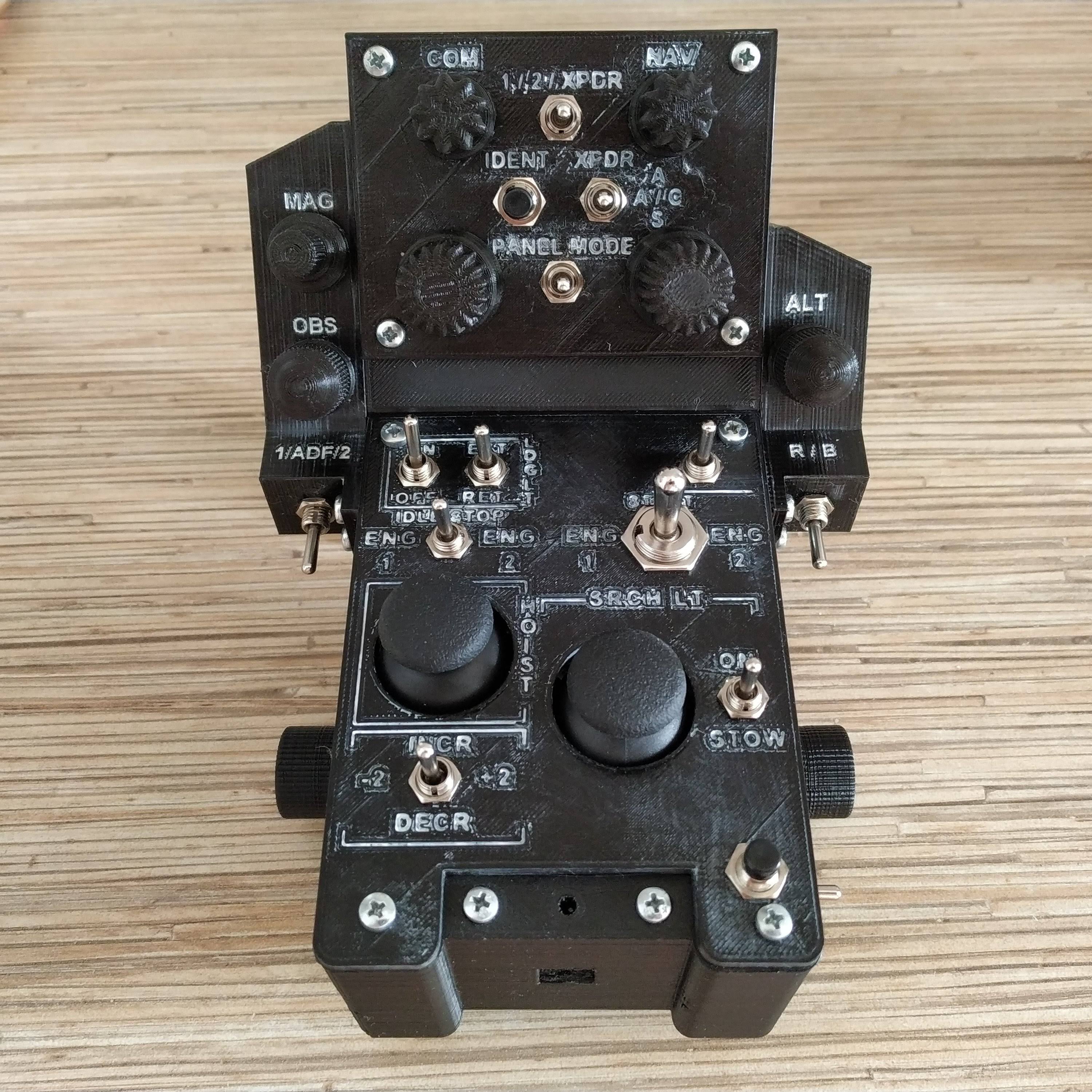
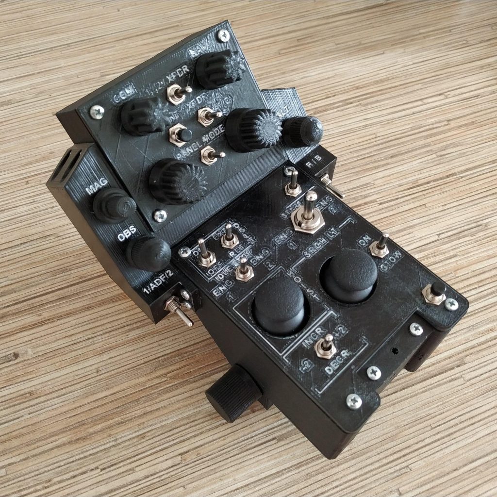
This is the most advanced collective head, that allows for complete control of your aircraft in VR. Currently, it’s based on the most feature-rich version of the AB412 head, but the most interesting is the VRMAX radio+ panel itself: as of now, it uses 154 joystick buttons, to allow you to map all the knobs you have in the aircraft. Here’s the list of it’s features:
- NAV / COM 1 and 2 (coarse / fine, ACT / STBY)
- transponder (code select, ident, mode select)
- directional gyro adjustment
- VOR 1 / 2 OBS knob
- ADF (frequency select / HDG)
- altimeters (barometric /radio)
- panel mode switch: 6 additional joystick buttons sets are mapped to radio panel knobs, depending on panel mode and stack selector switch positions
Components
- MTS-103 ON-OFF-ON switch * 5 pcs
- PBS-10B-2 button * 1 pcs
- PEC16-4220F-S0024 incremental encoder * 7pcs
Downloads
Assembly
IMPORTANT NOTICE: this is a very advanced and specialized device, please follow this manual to the letter, do not deviate. The code currently has some functions in it tied to particular knobs, so connections must be exactly as described below.
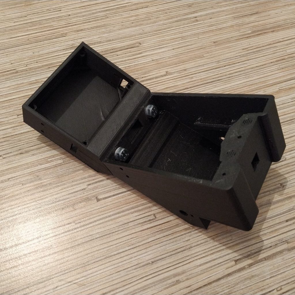
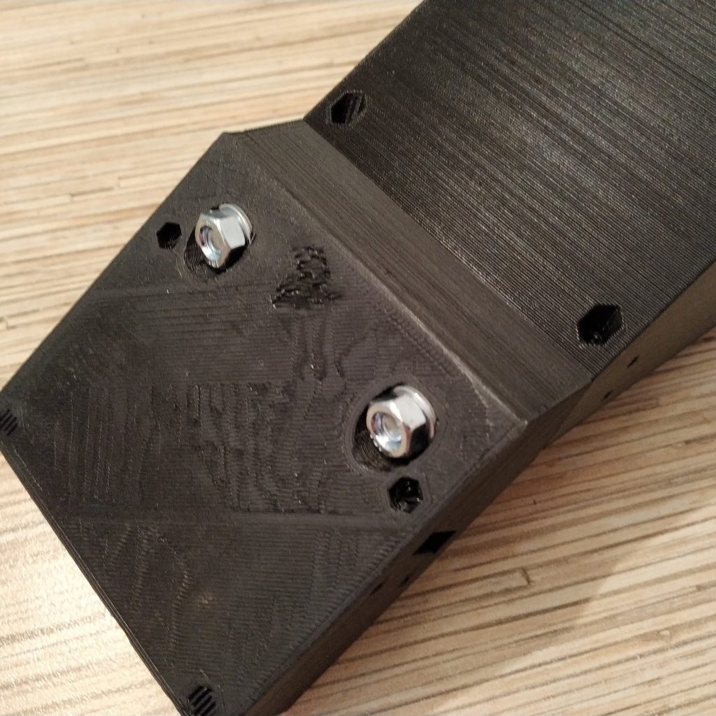
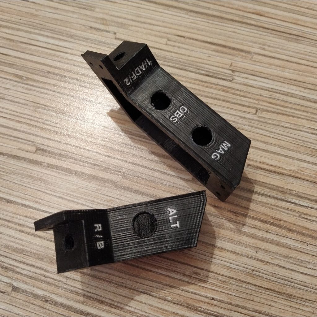
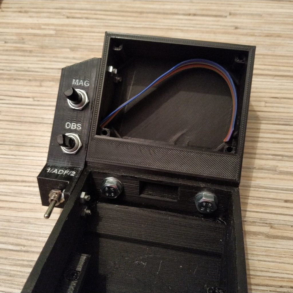
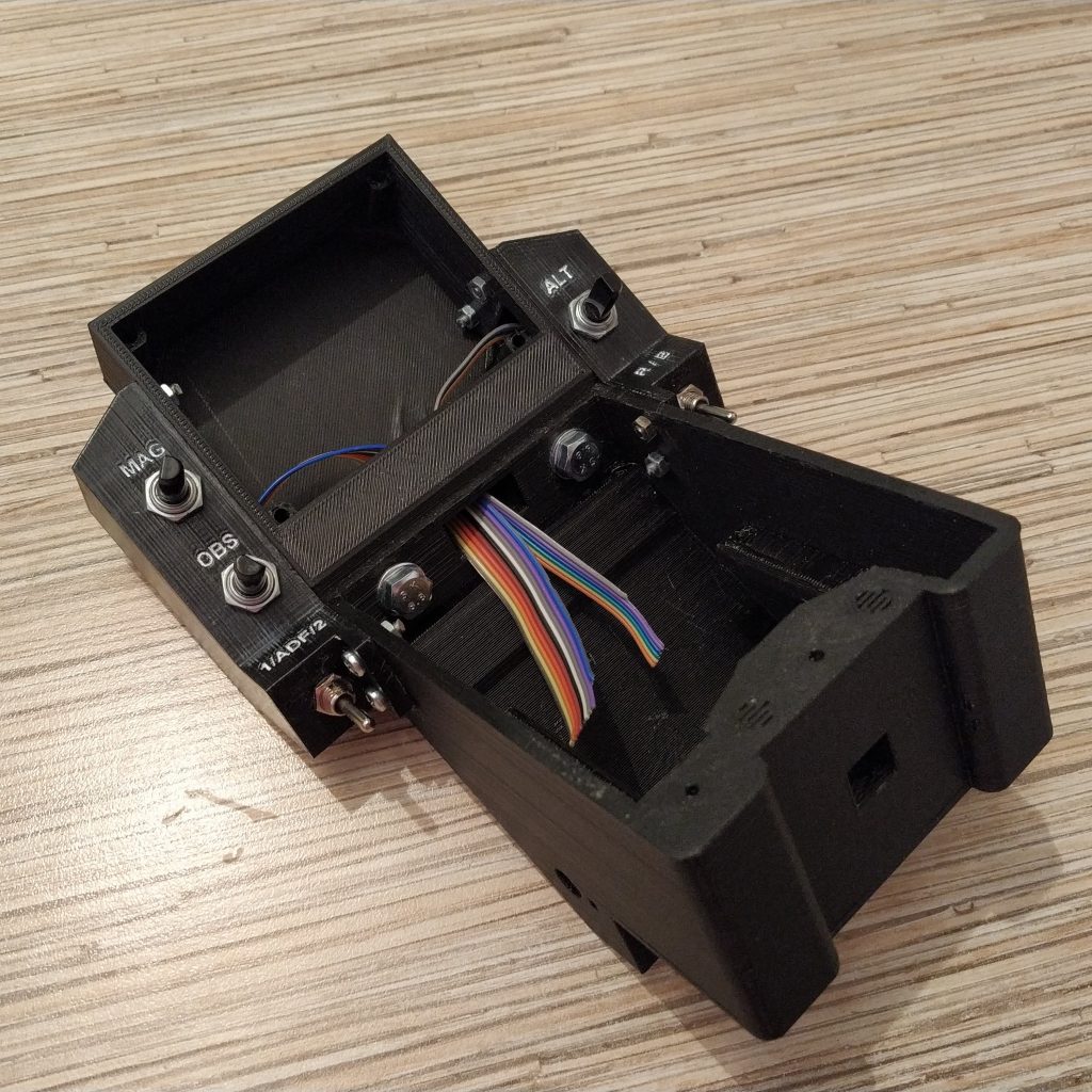
- Prepare housing parts, press-fit nuts into their sockets, pull a 10x10mm rail through its socket a few times to ensure the head can be easily put on and off. Connect 2 parts of the head with 2xM6x35mm bolts.
2. Apply paint to side panels if required.
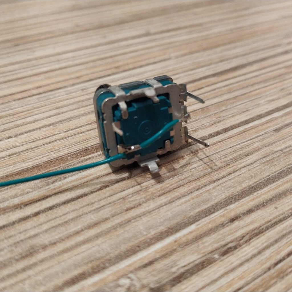
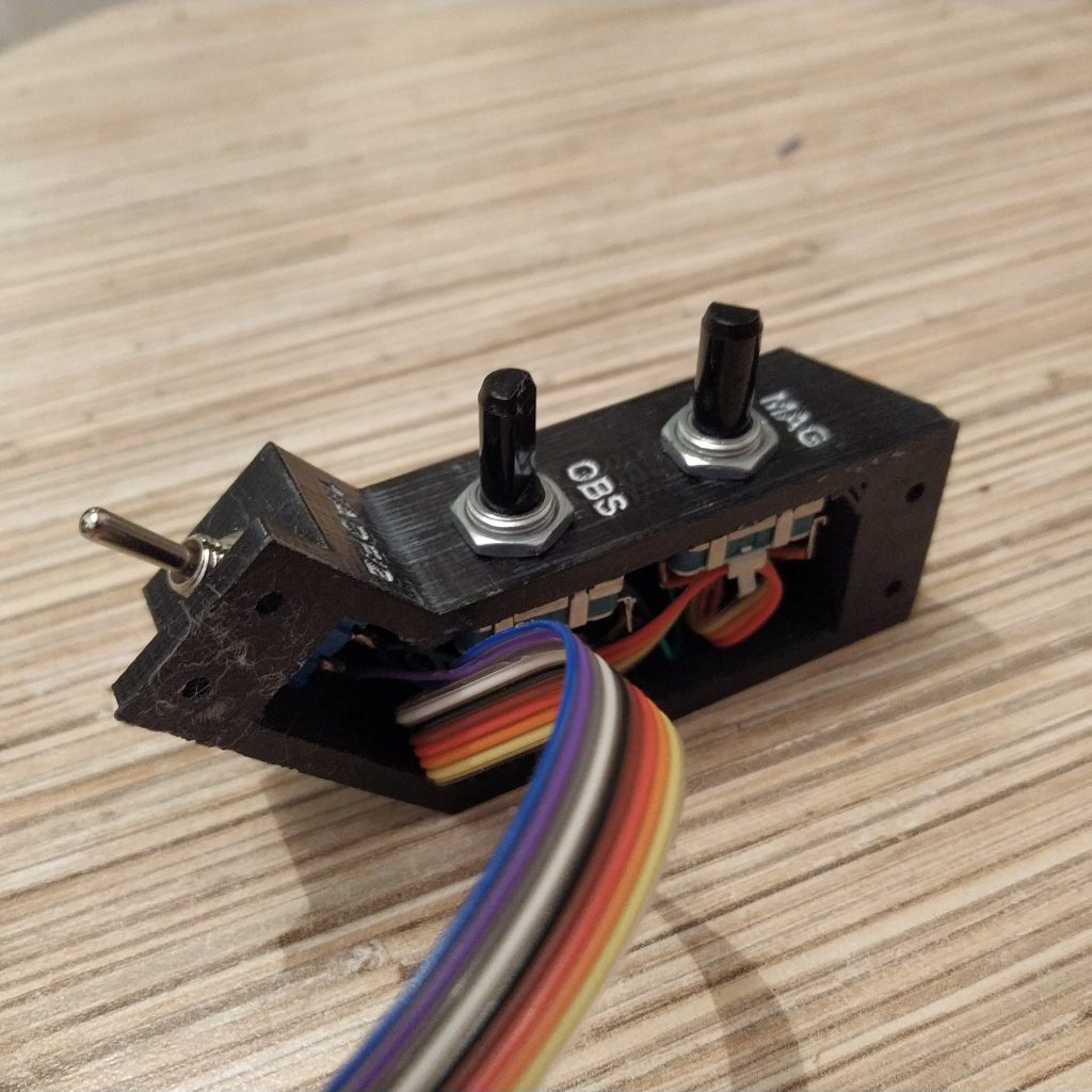
3. Solder ribbon cables to side panel switches and encoders. Start with ground. Mark one side of the switch with a dot, that will be the “top” side.
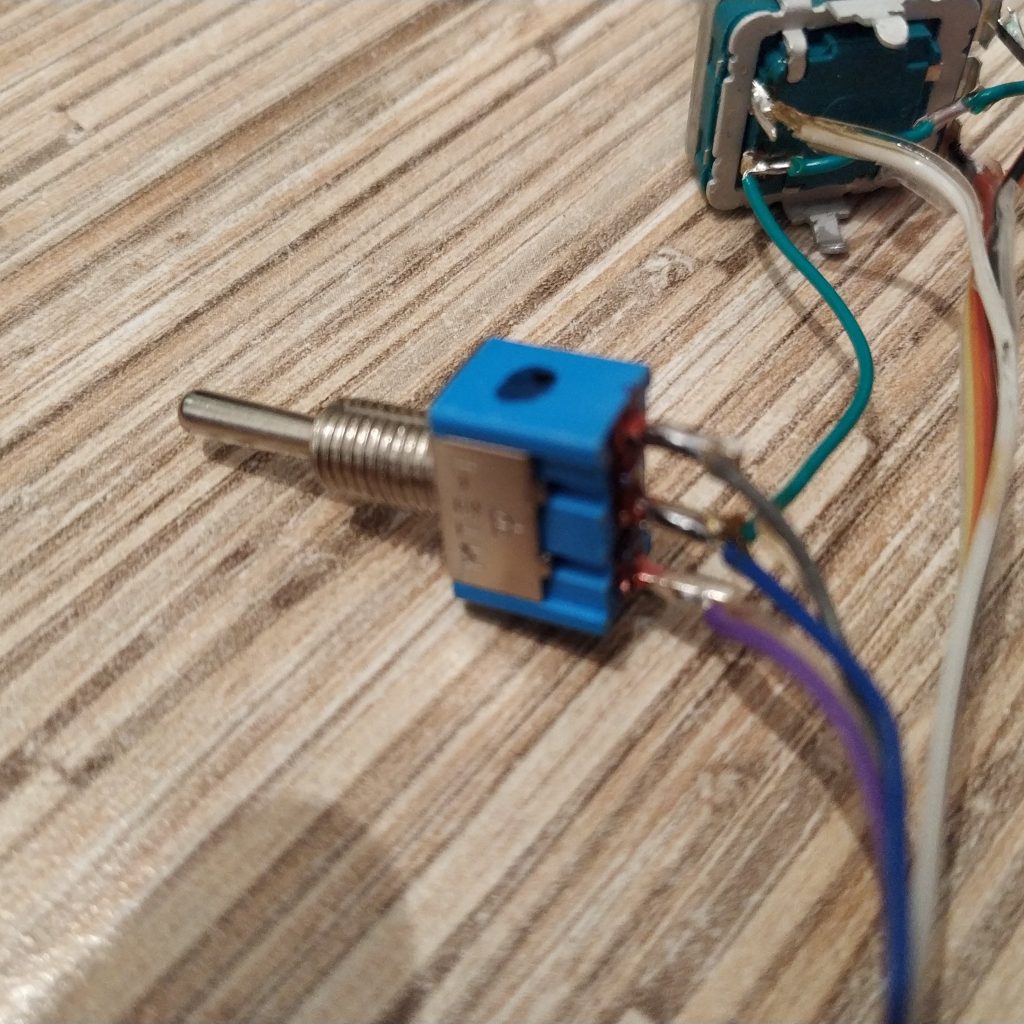
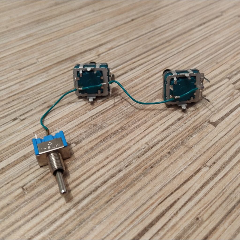
The order of wires in the ribbon is important. Put 2 rotary encoders in a line with their “thorn” thing facing left. Then, solder wires as follows:
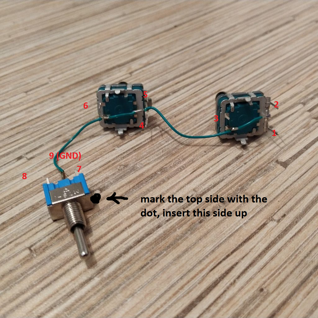
- Wire 1 -> ENC1 bottom pin
- Wire 2 -> ENC1 top pin
- Wire 3 -> ENC1 button pin
- Wire 4 -> ENC2 bottom pin
- Wire 5 -> ENC2 top pin
- Wire 6 -> ENC2 button pin
- Wire 7 -> “top” switch pin
- Wire 8 -> bottom switch pin
- Wire 9 -> GND
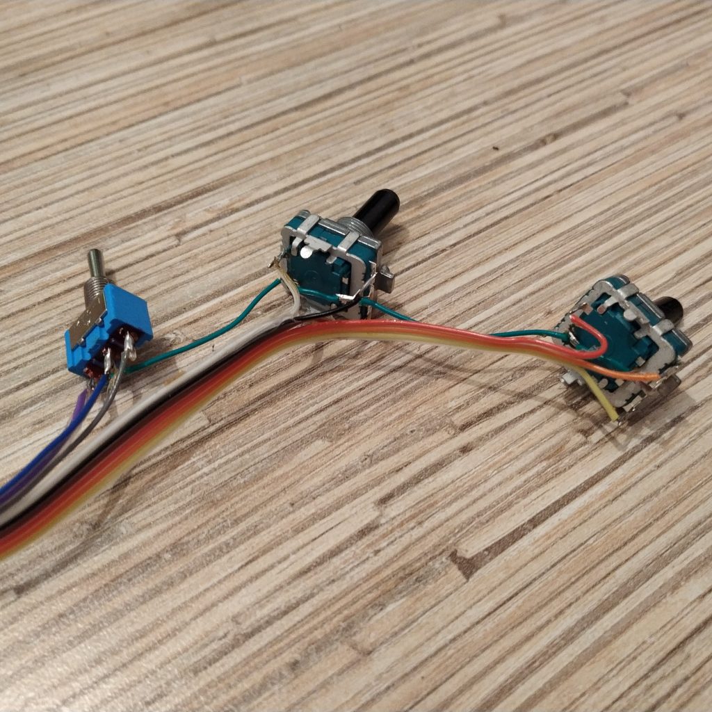
4. Insert encoders and the switch into side panel part. Make sure the dot on the switch faces up. Cut the GND wire on the other side so it will differ from others.
Cut “thorns” off encoders. Insert them with “thorn” side up.
Install the assembly to the head housing. Fix with 4 M3x10mm screws.
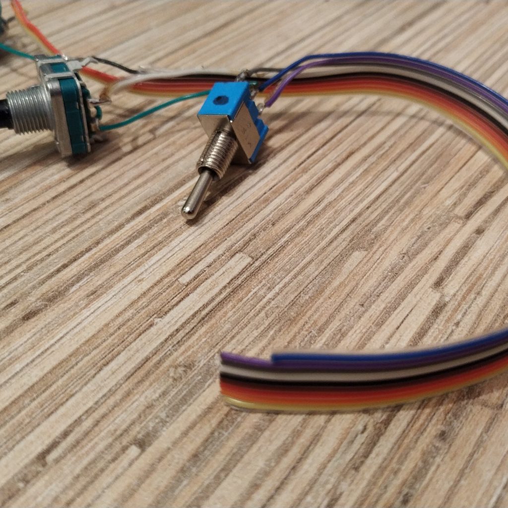
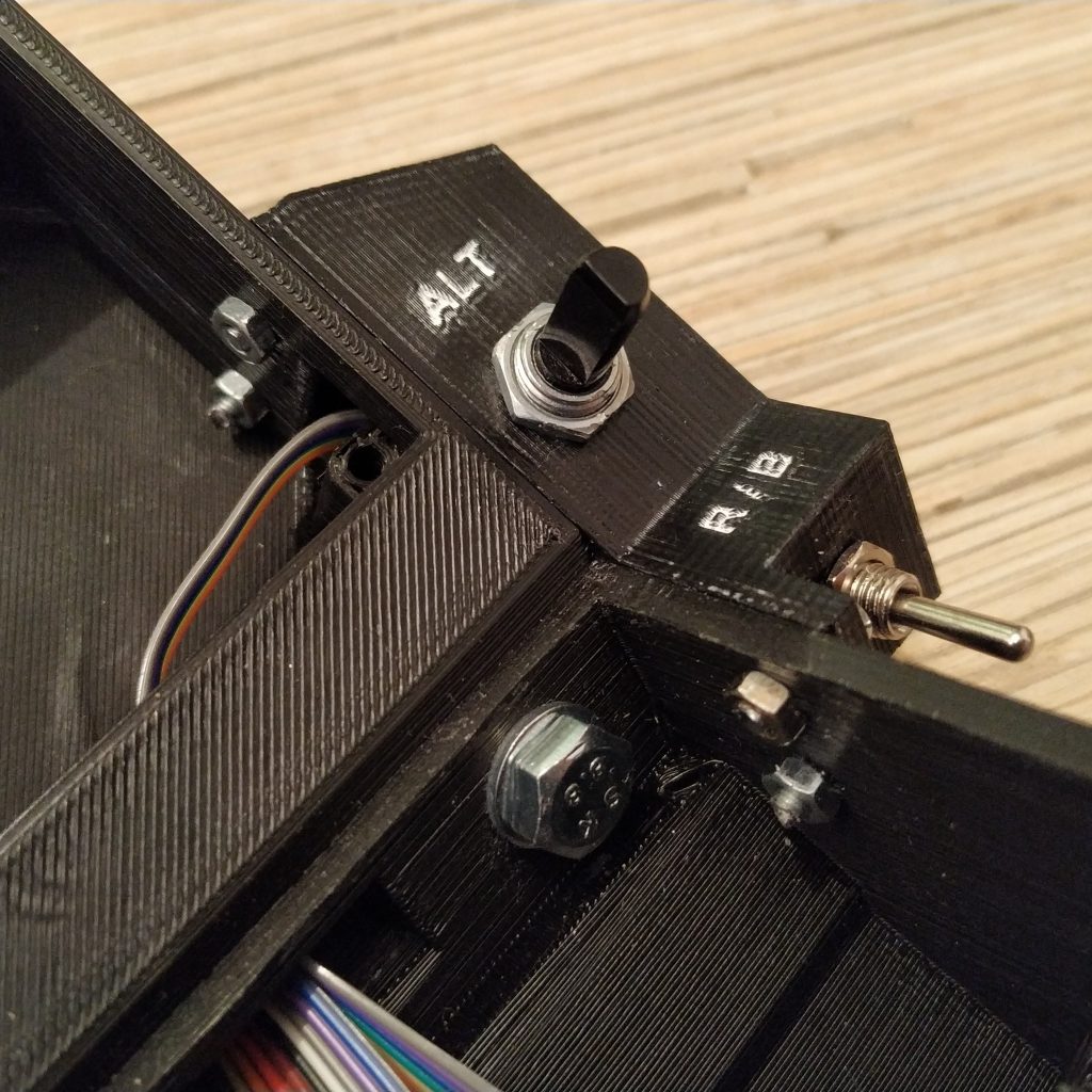
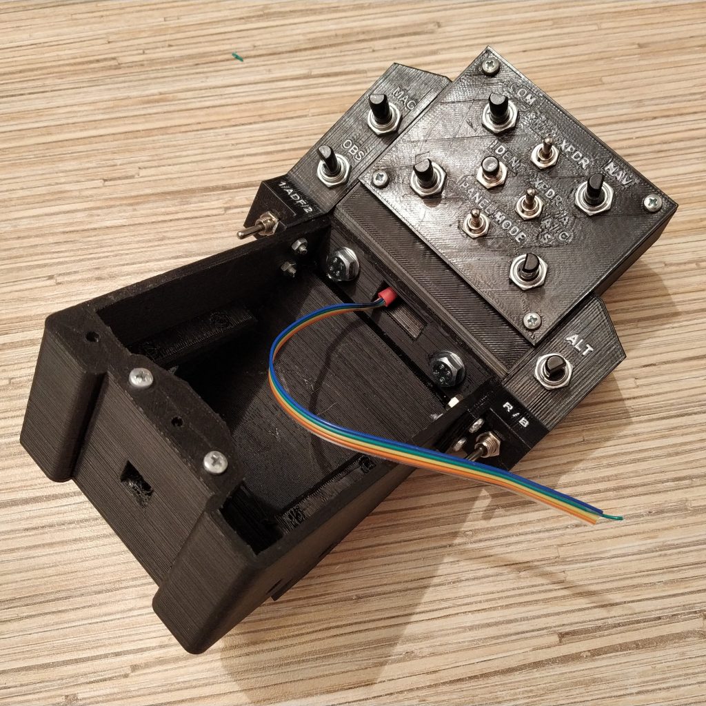
5. Repeat the process with the ALT knob assembly. Start with soldering the GND wire
Proceed with soldering wires of a 6-wire cable as follows, starting from the encoder bottom pin.
- Wire 1 -> ENC1 bottom pin
- Wire 2 -> ENC1 top pin
- Wire 3 -> ENC1 button pin
- Wire 4 -> “top” switch pin
- Wire 5 -> bottom switch pin
- Wire 6 -> GND
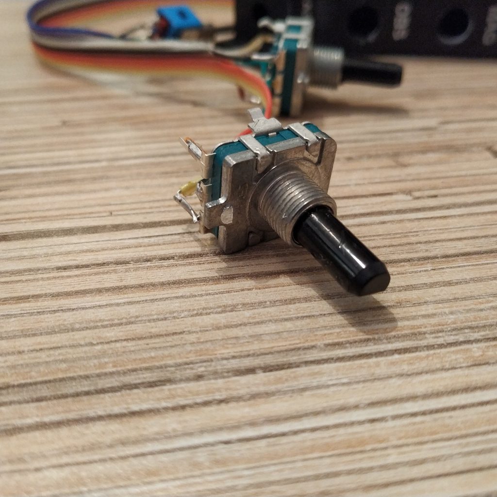
Insert the encoder and the switxh into the ALT knob housing. Fix with 4 M3x10mm screws.
6. Apply paint to the radio panel cover if desired. Insert switches and encoders.
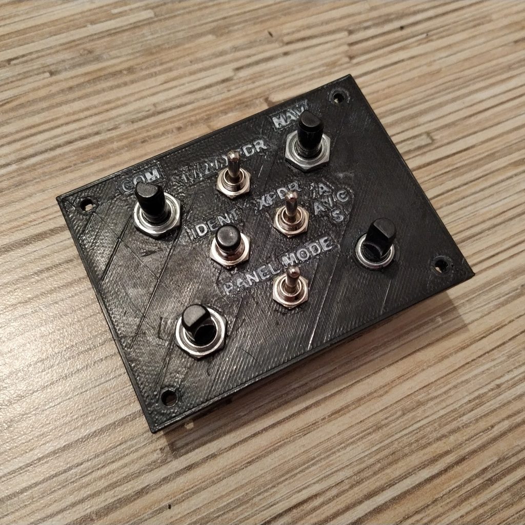
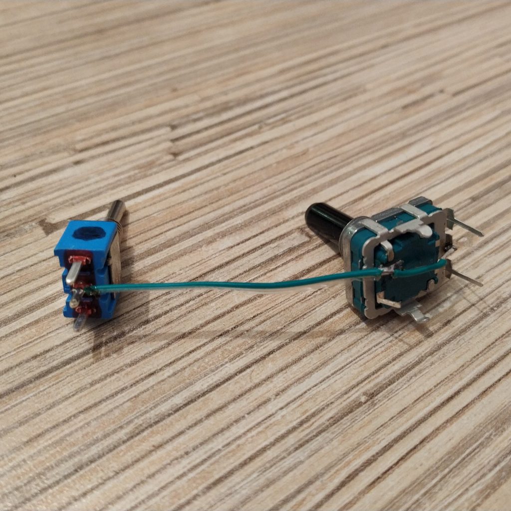
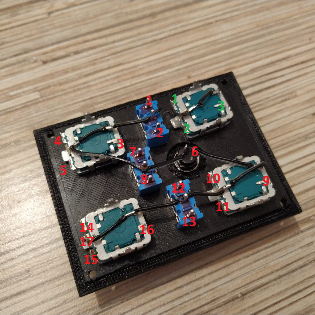
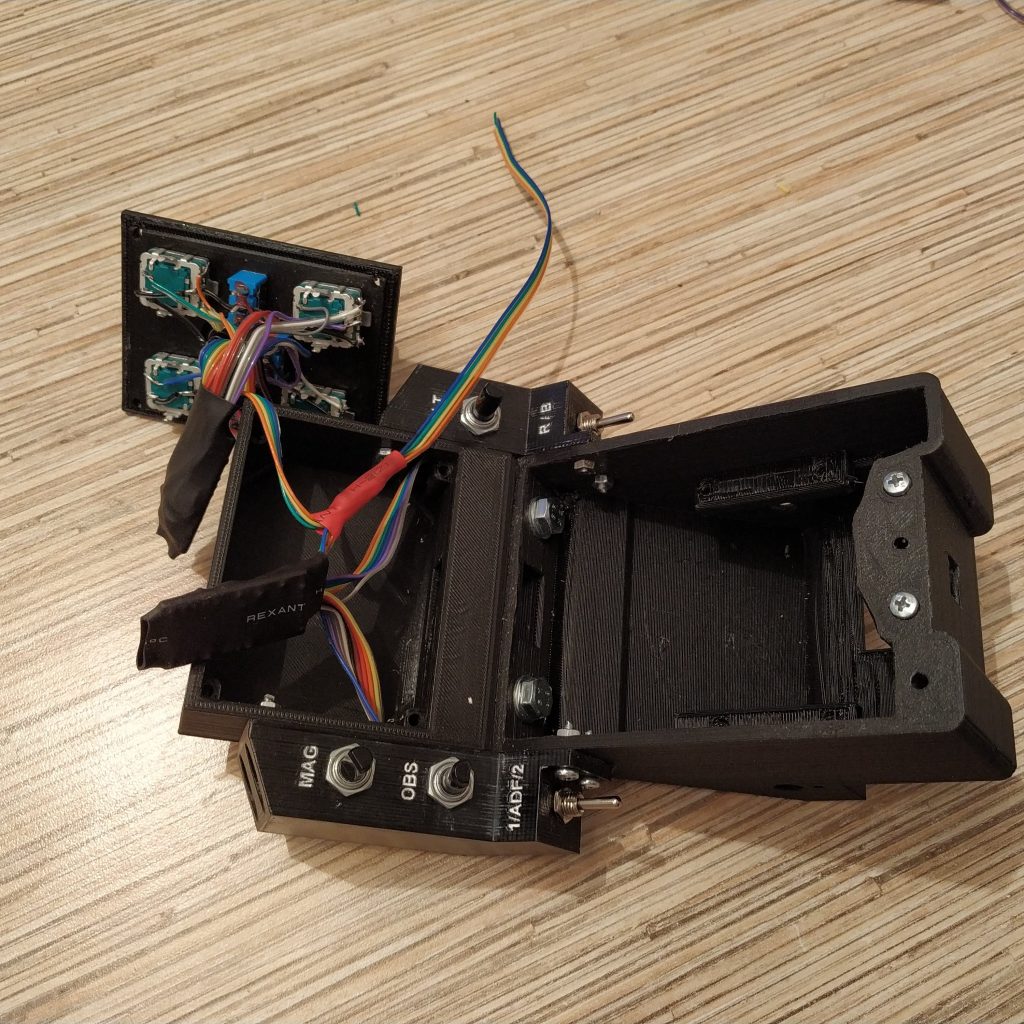
7. Turn the panel around so the COM and NAV letters will still be on top. Solder the ground wire as shown on the next picture.
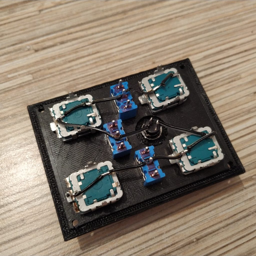
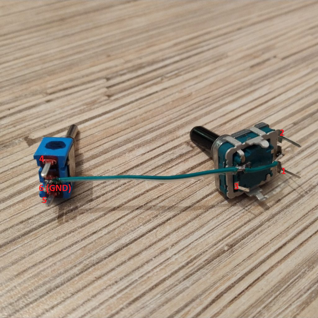
8. After soldering the ground wire, solder a 17-wire cable (red numbers), strictly following order on the picture below! When finished, solder a 3-wire cable to the top-left potentiometer, following green numbers.
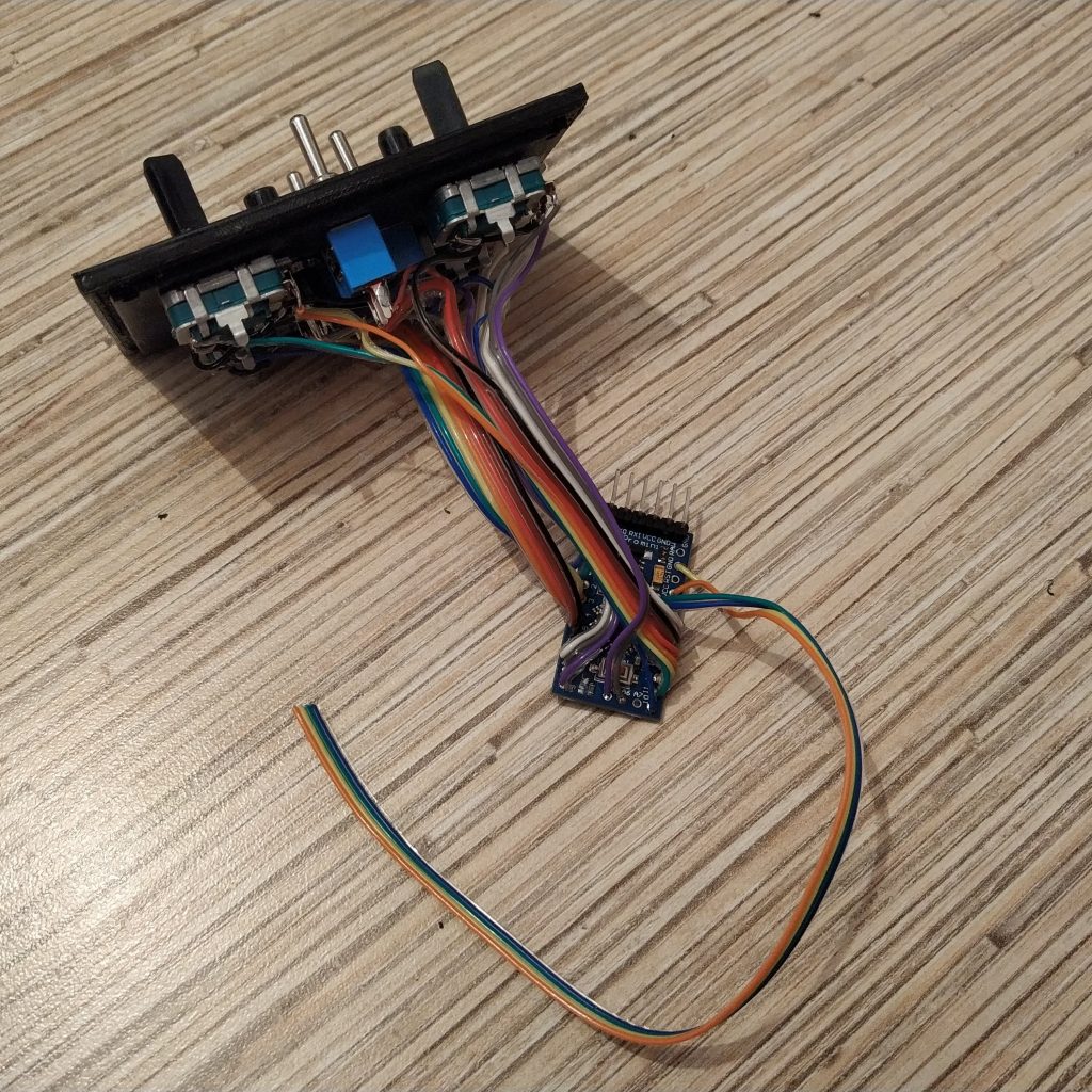
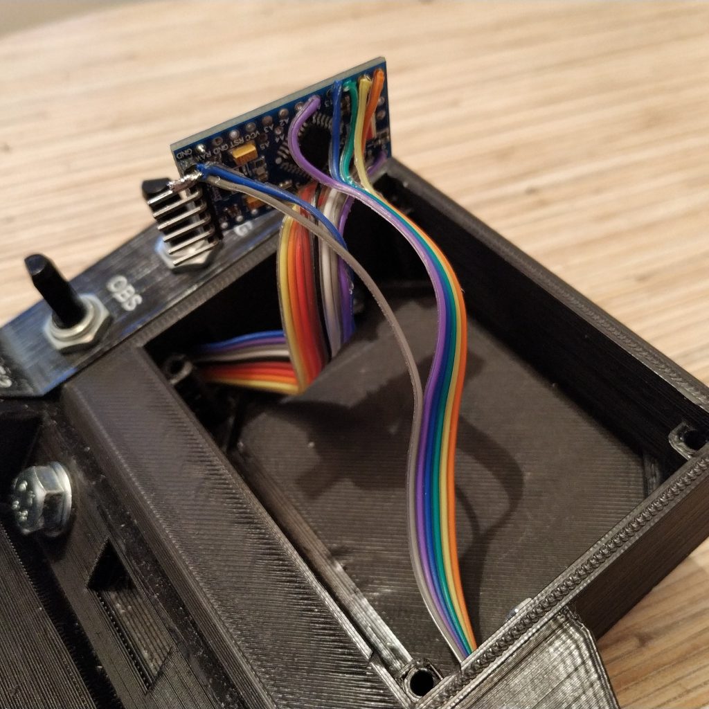
9. Solder the other end of the ribbon to Pro Mini, starting with the pin 3 through pin A3 one by one correspondingly, leave pins A4 and A5 free.
Solder wire 16 to pin 2. Remove LED on pin 13.
Wiring diagram:
RED
- pin 3
- pin 4
- pin 5
- pin 6
- pin 7
- pin 8
- pin 9
- pin 10
- pin 11
- pin 12
- pin 13
- pin A0
- pin A1
- pin A2
- pin A3
- pin 2
- GND
GREEN
See step 11
10. Solder I2C 4-wire cable to the board as follows:
- 5V -> Arduino VCC
- GND -> Arduino GND
- SCL -> A5
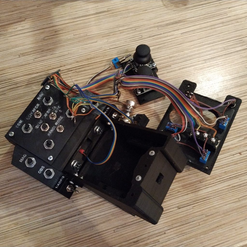
- SDA -> A4
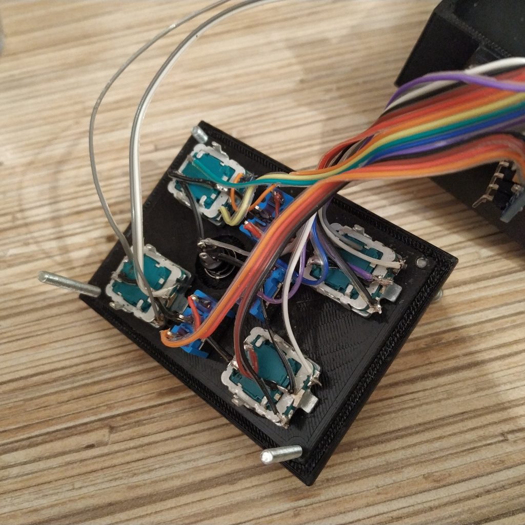
11. Solder side panel cables to another Pro Mini, start with the left one. Solder the 1st wire of its cable (remember, the short wire is the last one! to pin 2 of the Arduino board, 2nd to pin 3, 3rd to pin 4, and so on, up to pin 9. The last (GND) wire of the cable must be tied with the last wire of the right side panel and soldered to available GND pin. The cable from the right panel should start at pin 10, and the final wire should end up soldered to A0 pin. Solder 3 wires-cable, marked green on a picture in step 8, to pins A1, A2, and A3 correspondingly.
Wiring diagram:
Left side panel cable
- pin 2
- pin 3
- pin 4
- pin 5
- pin 6
- pin 7
- pin 8
- pin 9
Right side panel cable
- pin 10
- pin 11
- pin 12
- pin 13
- pin A0
Green cable from step 8
- pin A1
- pin A2
- pin A3
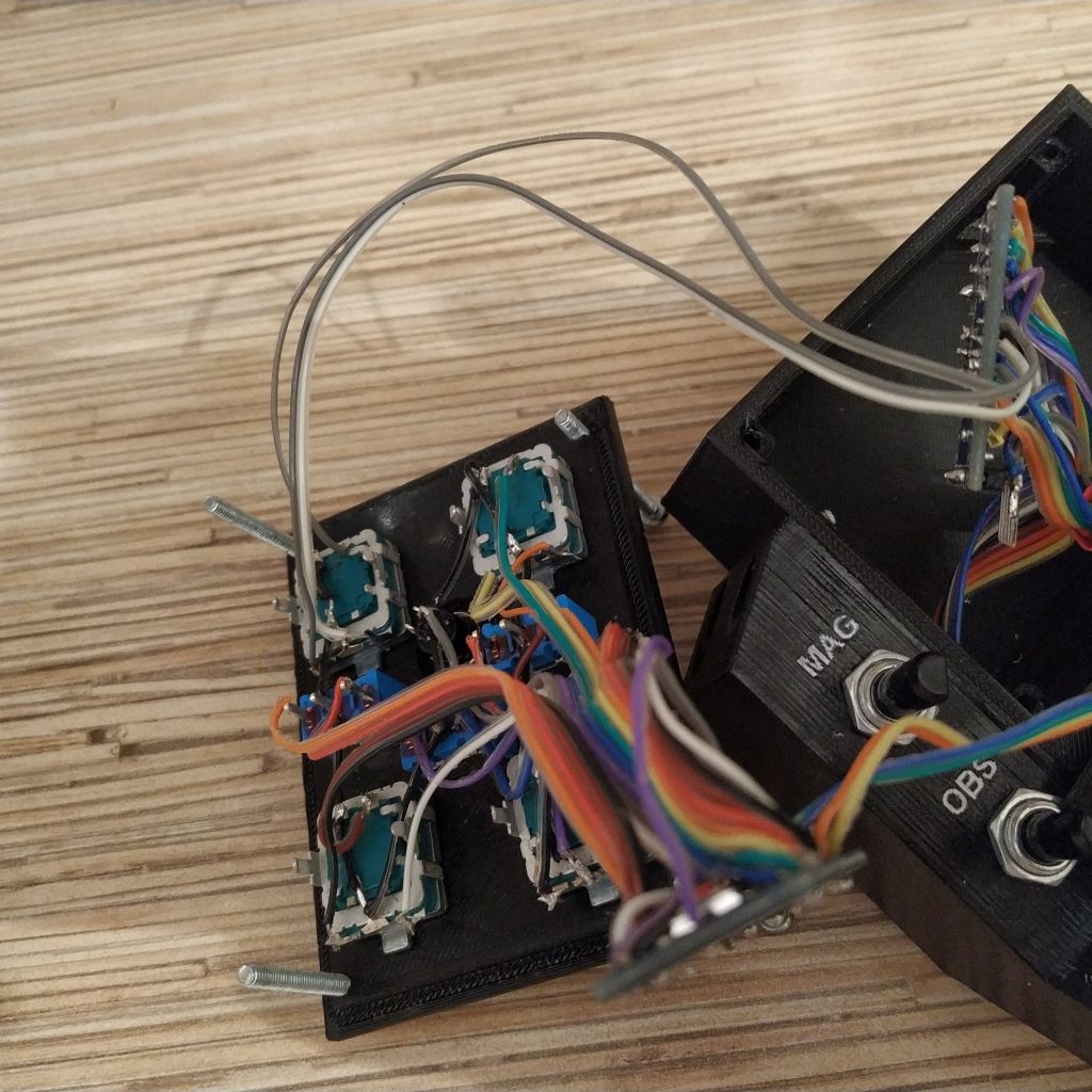
12. Solder 4-wire I2C cable to the side panel Pro Mini board. Connect I2C cables of radio and side panels together. Flash the boards with corresponding software.
13. Complete the radio panel assembly by closing the cover. Now, follow the AB412 head assembly manual. The only difference will be connecting the I2C cable of the radio panel to those of the 412 head.
14. Apply paint to the lid of the AB412 head top panel. Follow the AB412 head assembly manual up to and including step 10.
15. Check everything, using https://html5gamepad.com/. This tool can show any number of buttons. You can check hat switches operation in joy.cpl. The radio panel uses 142 buttons of the 2nd Arduino Leonardo in the list.
Congratulations! Enjoy your new collective head =)