Components
1 * 300x10x20mm aluminum square pipe
2 * 120x10x20mm aluminum square pipe
1 * SS495A hall sensor
1 * 6x6x4mm or 5x5x5mm square magnet
2 * M3x16mm screws for the SS495A mount
4 * M3x50mm screws for the cover
3 * M8x75 bolts
2 * M8x16 bolts
2 * M8 nyloc nuts
6 * 608 bearings (standard skateboard bearings)
cyanoacrylate to glue SS495A and a magnet
1 * Simchair MKIII I2C controller
1 * ADS1115 ADC
2 * LADA2101 clutch pedal spring or similar (1,2mm thick, 11,5mm diameter, 53,7mm height without hooks, ~81mm with hooks when squeezed). Any similar spring with light to moderate tension should work. You can also order them from me in any quantity if you can’t find one at your place. Alternatively, rubber bands can be used.
Important notice
For pedals, use higher temperature when printing parts. Depending on how tightly your thermistor is fastened to the heater block, you may need to go as high as 215-225 degrees, though it’s uncommon for PLA. Parts should have a glossy finish and should not crack when you assemble stuff! I recommend printing one of the frame legs for a test and trying to fit it onto an aluminum tubing piece. If it cracks, increase temperature.
Special features
- pseudo force trim support for both rubber-bands based and spring-loaded versions (different modes)
- in-flight sensitivity switching support
Downloads
Assembly
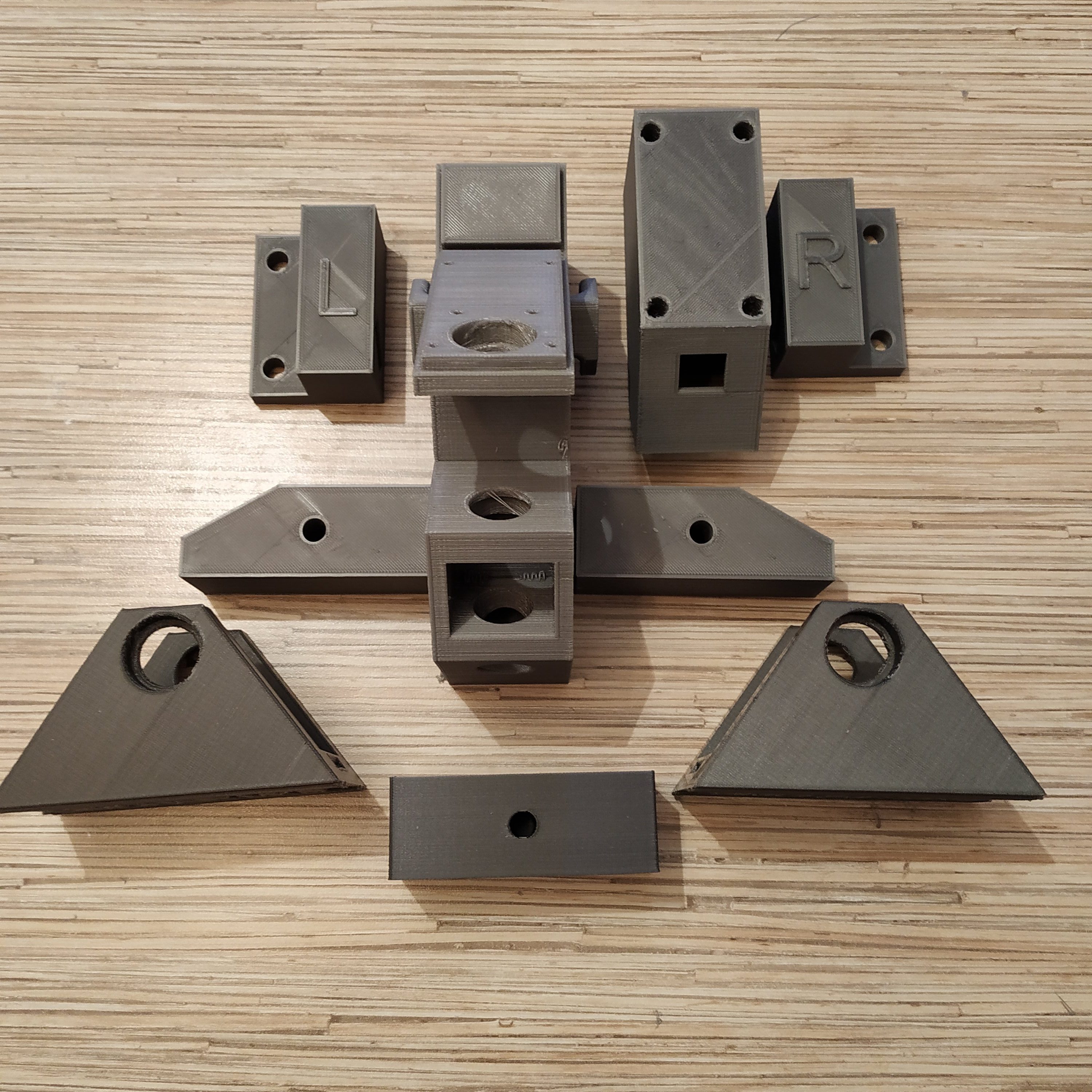
- Clean all printed parts from supports.

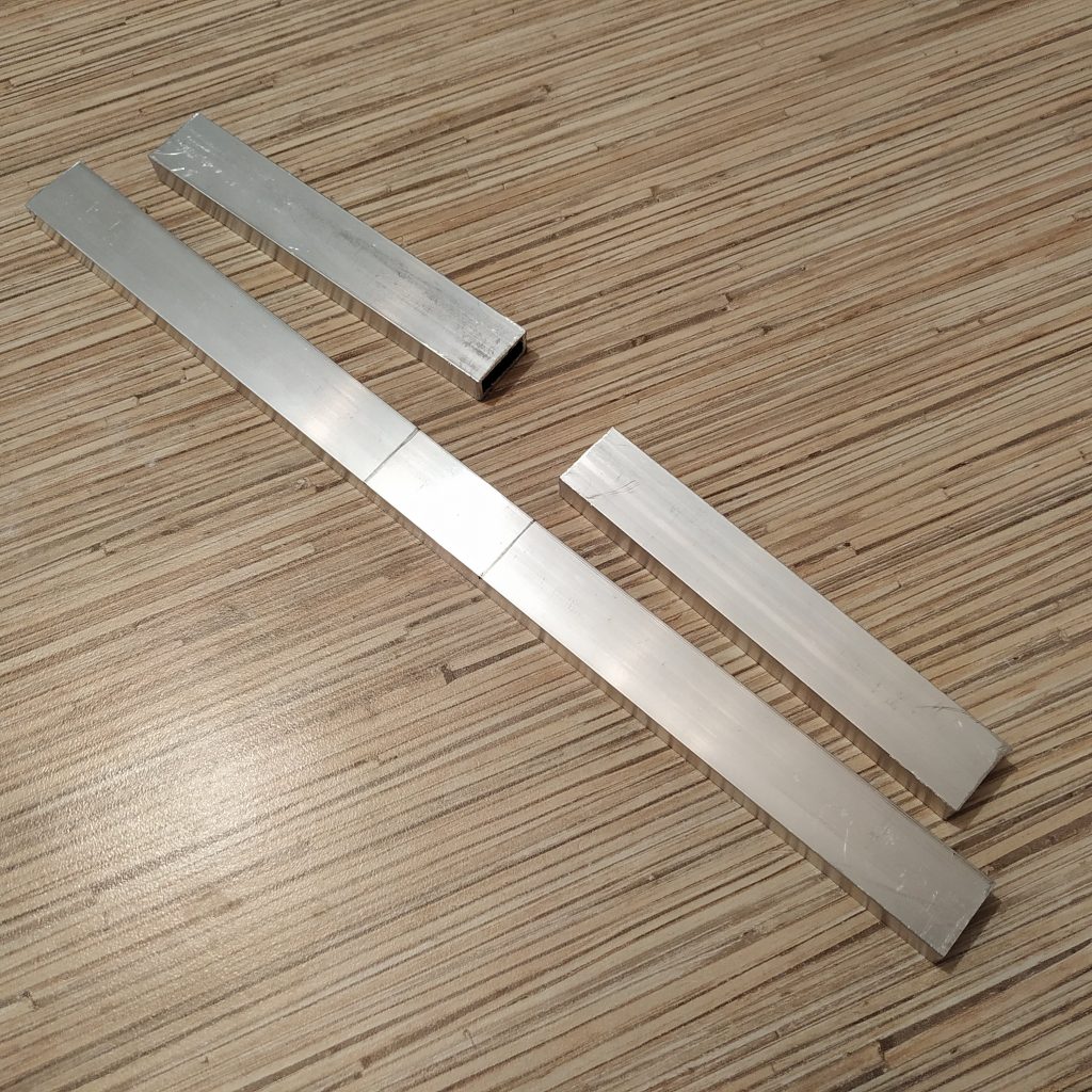
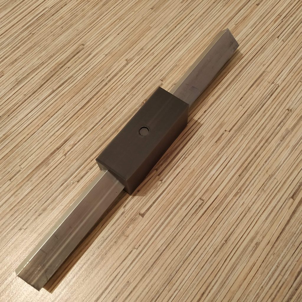
- Saw off a 300mm and 2x 120mm pieces of 10x20mm square tubing. File sharp edges. Make marks at 130mm from the edge on the 300mm tubing piece.
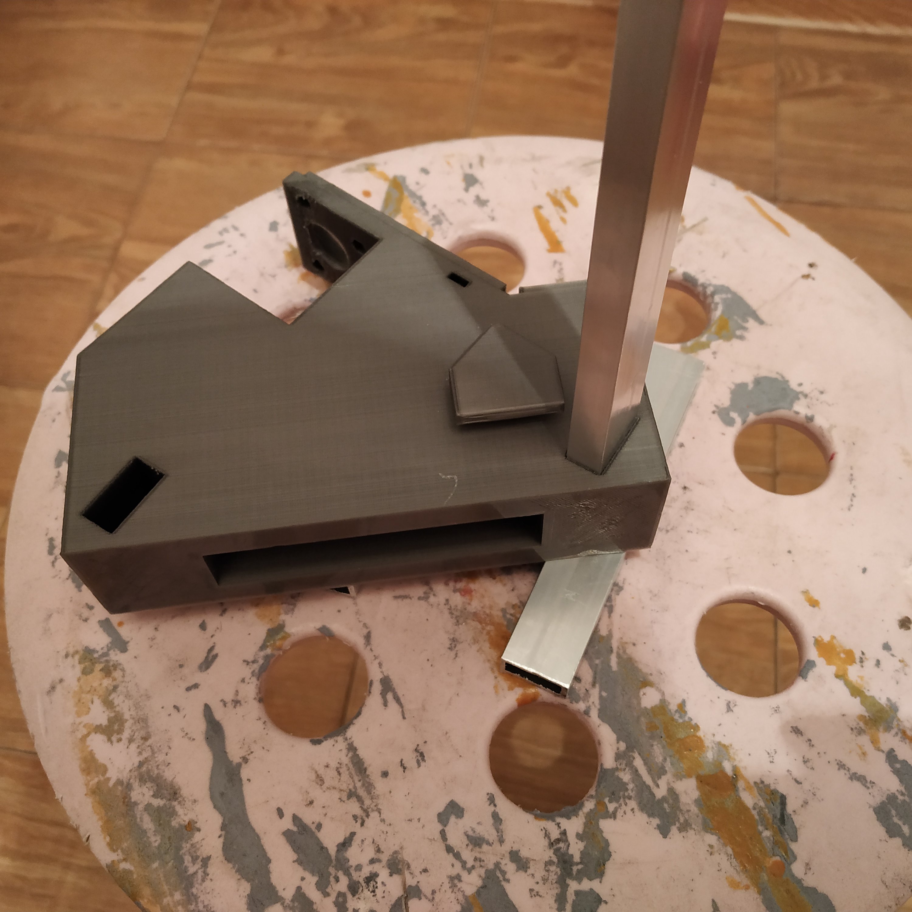
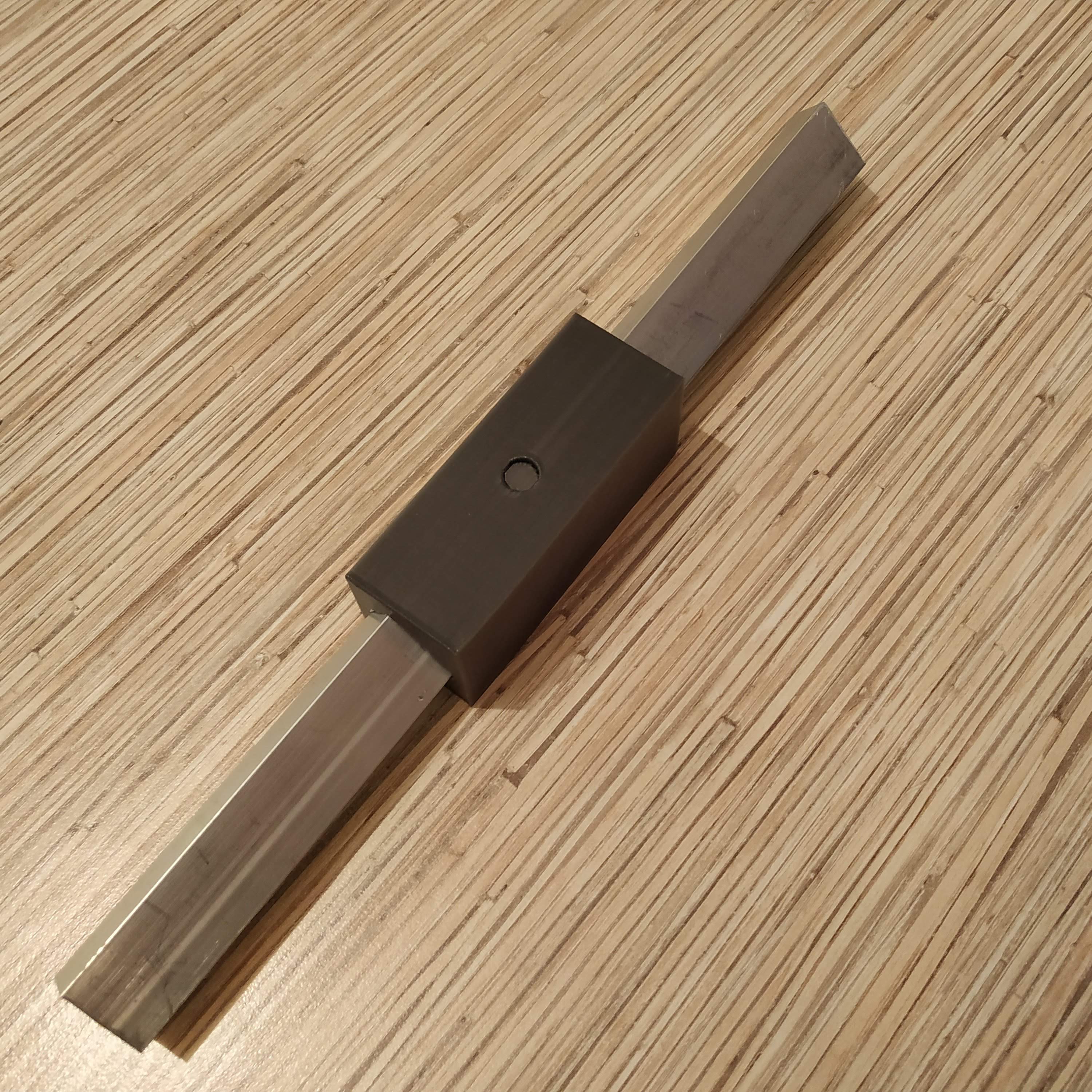
- Press fit the 30mm piece into the frame carefully so the marks will match frame sides. File as needed. Use 120mm tubing piece as detents.
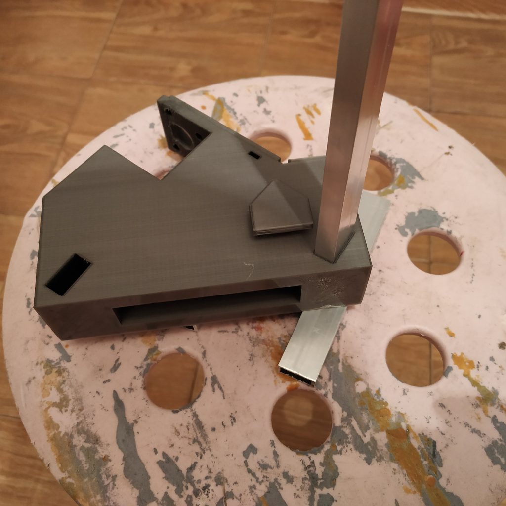

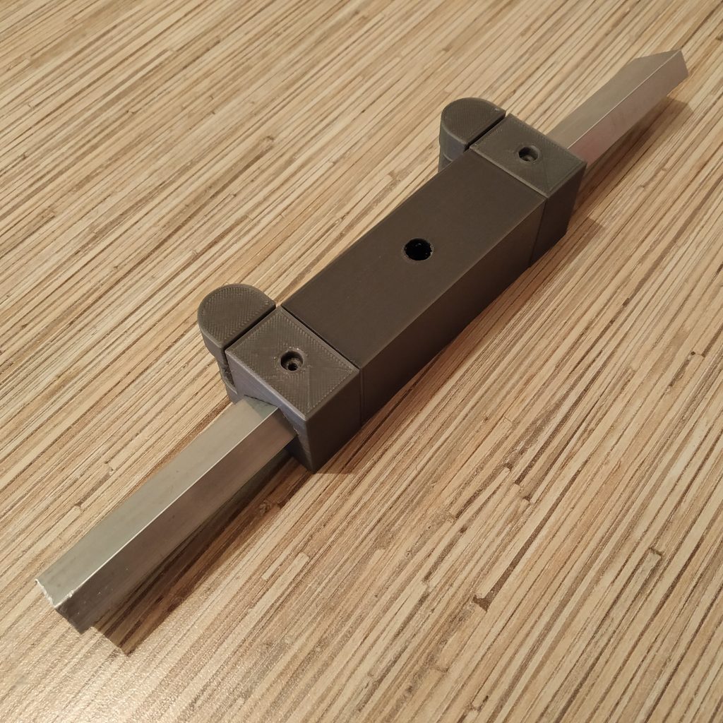
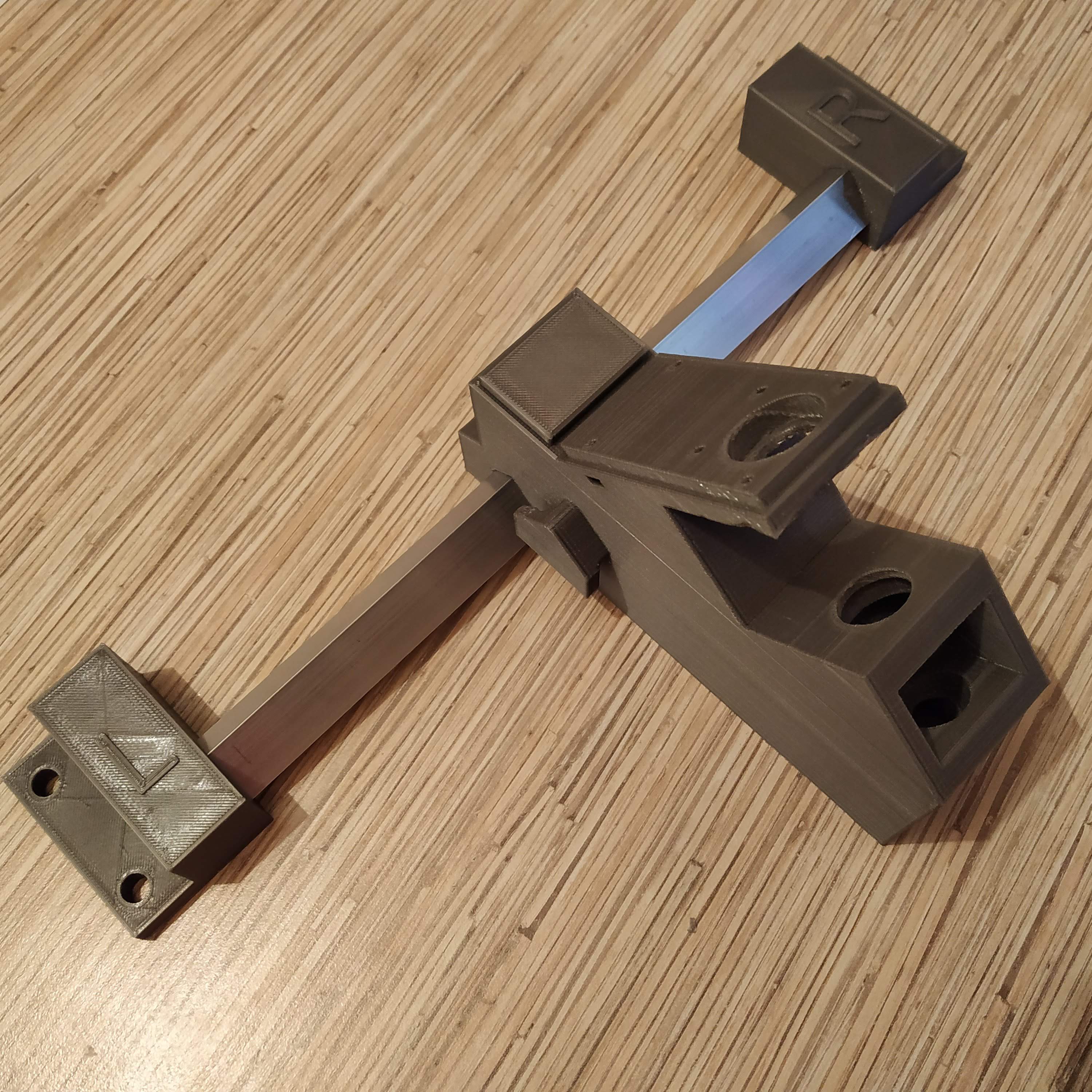
- Using 120mm pieces as detents, put frame legs onto the 300mm tubing piece.

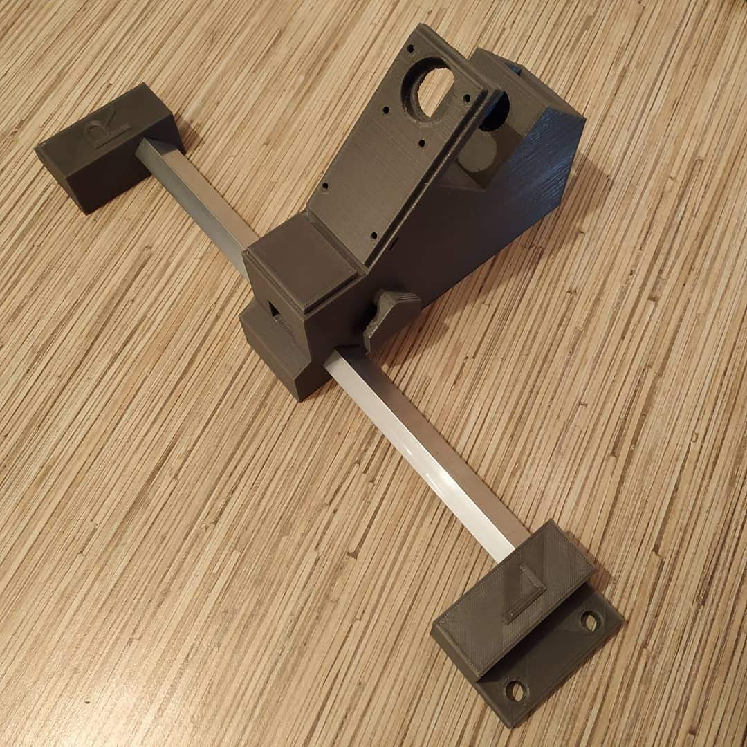
- Press-fit 120mm tubing pieces into their slots in the rocker part. Position it with its bottom side (as printed) pointing backward (towards the frame).
- Press-fit rubber band holders onto 120mm tubing pieces. I recommend installing these parts regardless of whether you are planning on using rubber bands or springs, as they strengthen the frame additionally.
- Press-fit pedal holders onto 120mm tubing pieces, with their sides, that have been facing the heatbed during printing, facing downwards for a cleaner look.

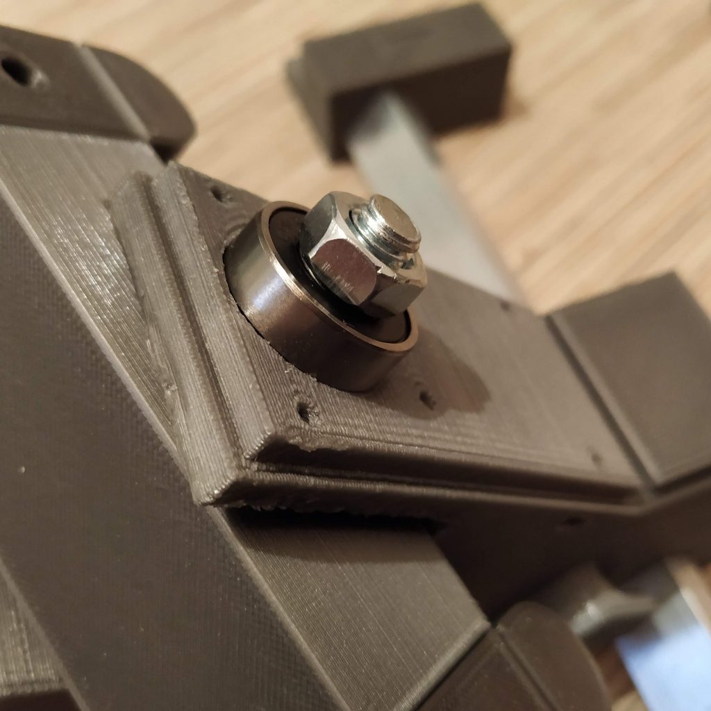
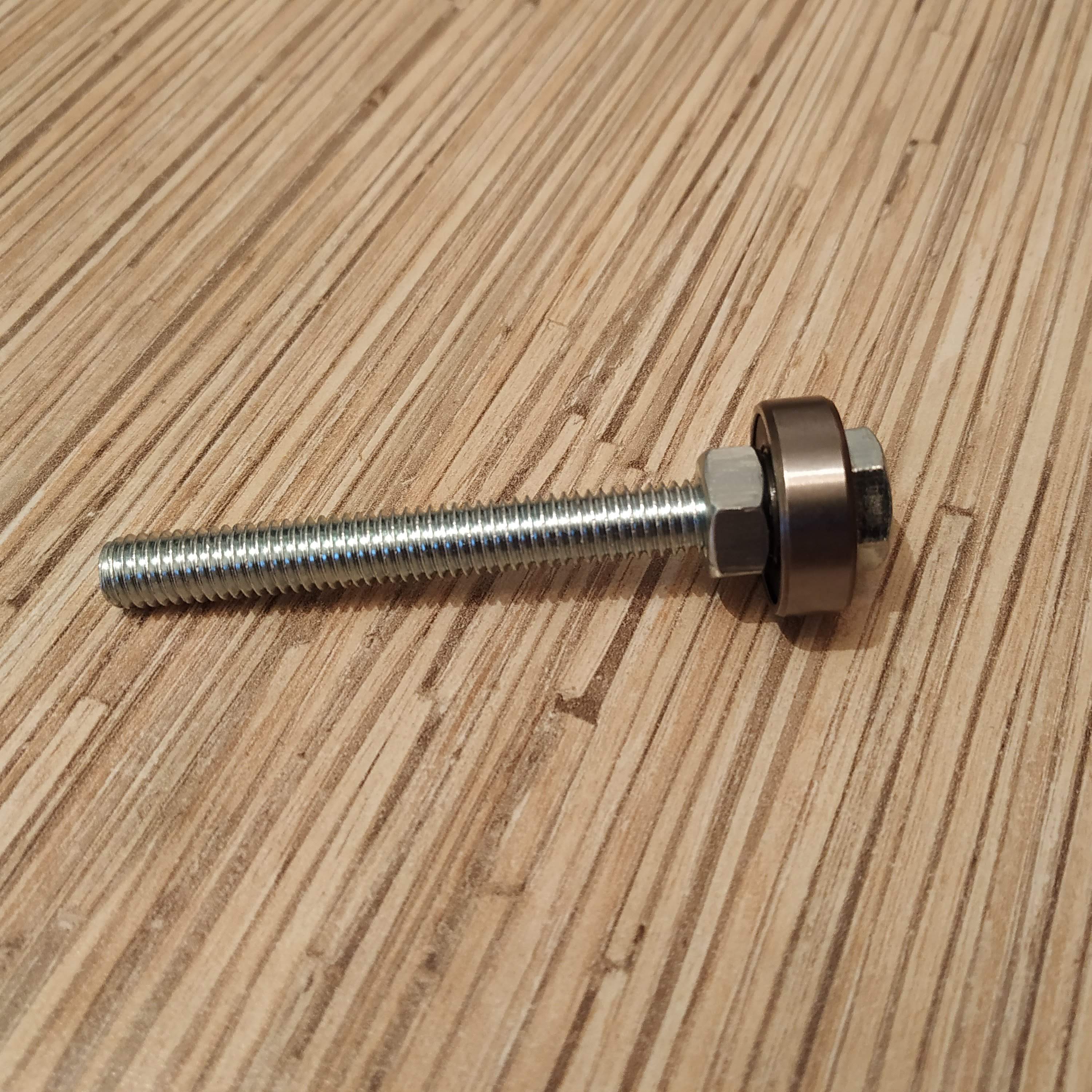
- It’s time to put pedals onto their holders. Take an M8x75mm bolt and put a bearing, and a nut, onto it. Tighten firmly. We will be inserting this bolt from the top side of the pedal (make sure the pedal is positioned correctly, rubber band holders should be facing upward with their slots. Screw it fully into the pedal holder., press-fitting the upper bearing in the process.
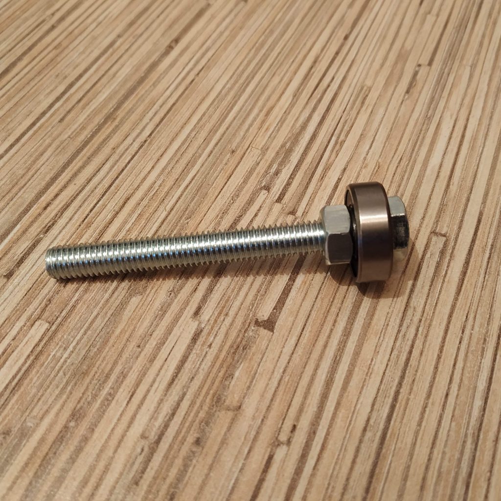

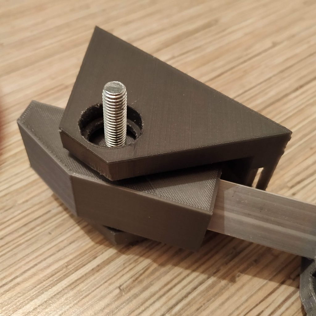
- Put another nut onto the bolt and tighten it.
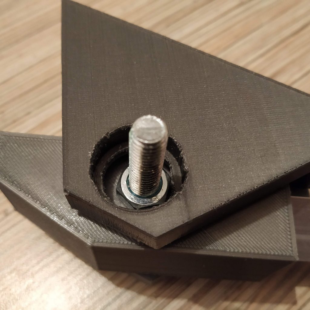
- Put a spring washer onto the bolt.
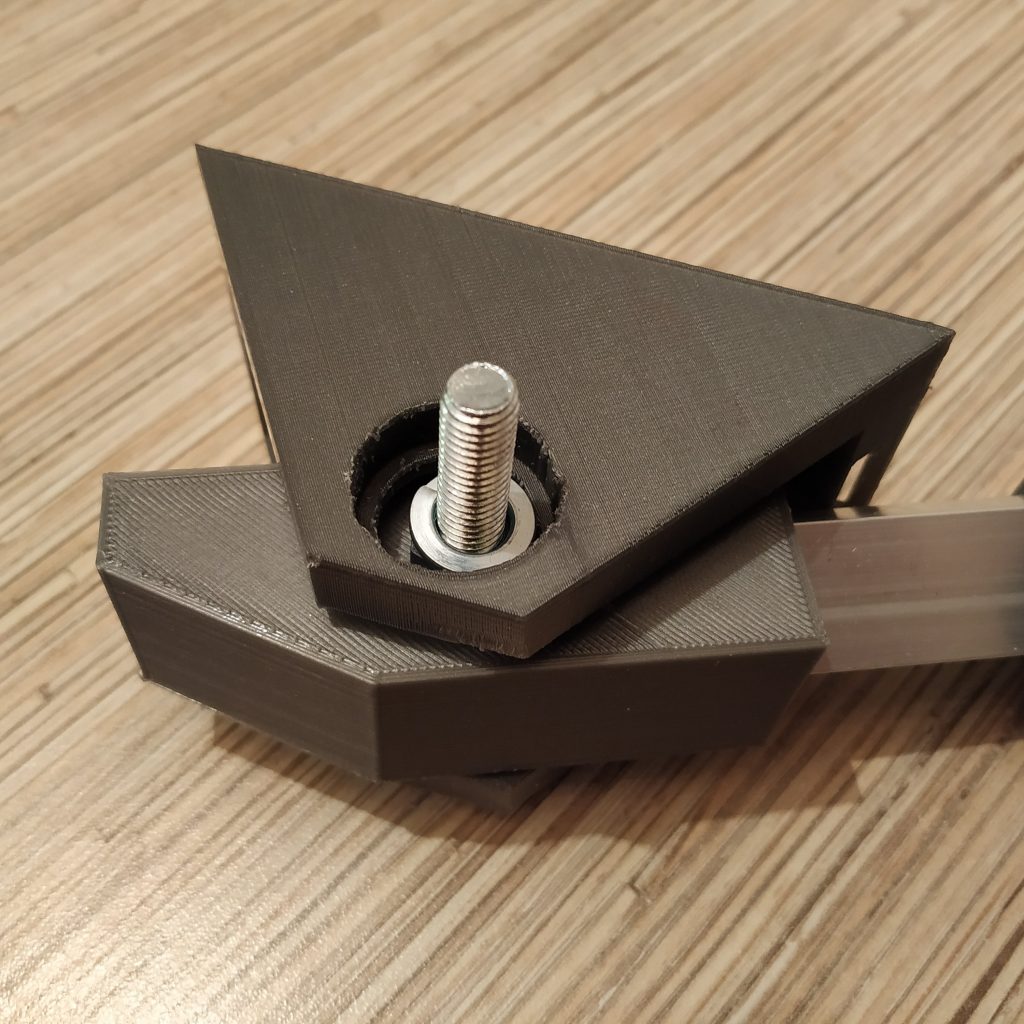
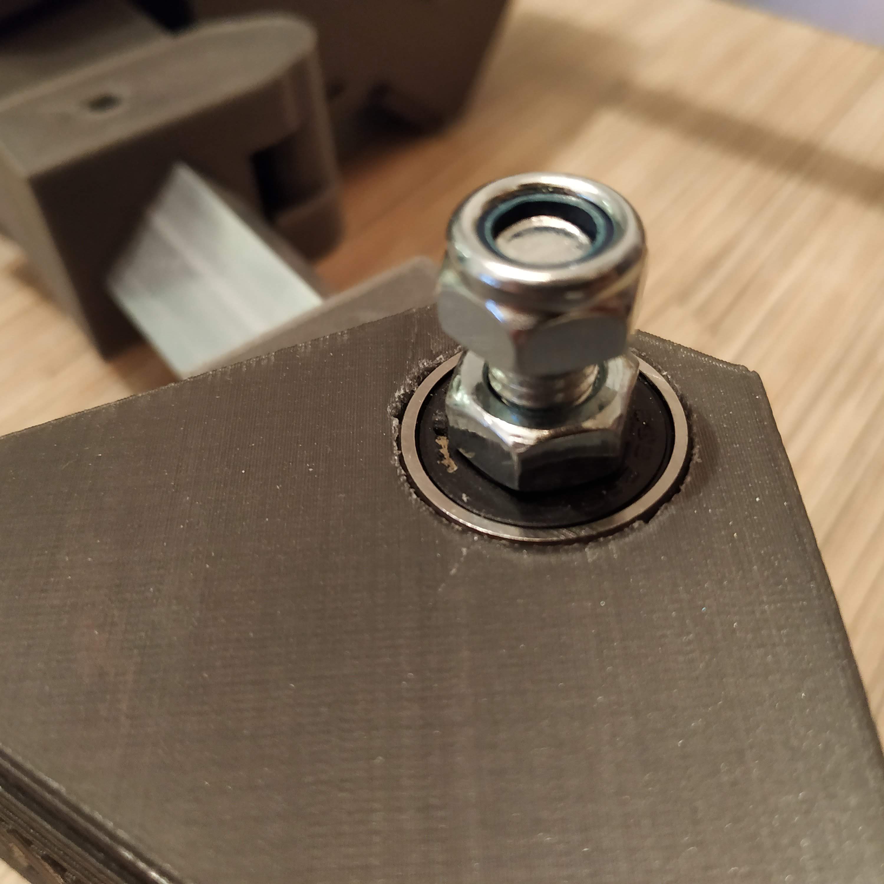
- Put another bearing and a nut onto the bolt, and press-fit the bearing while tightening the nut. Tighten everything firmly, there should be no backlash.
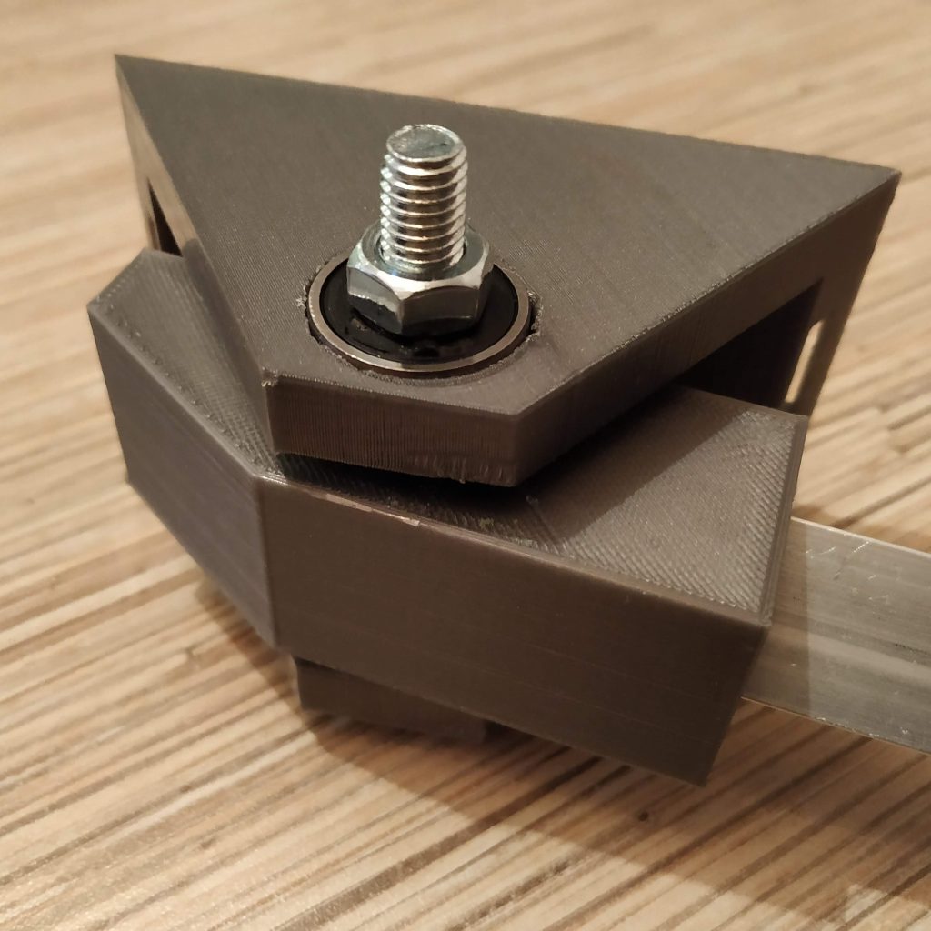
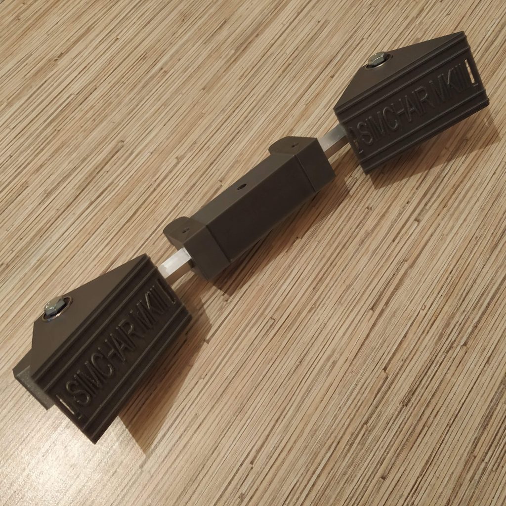
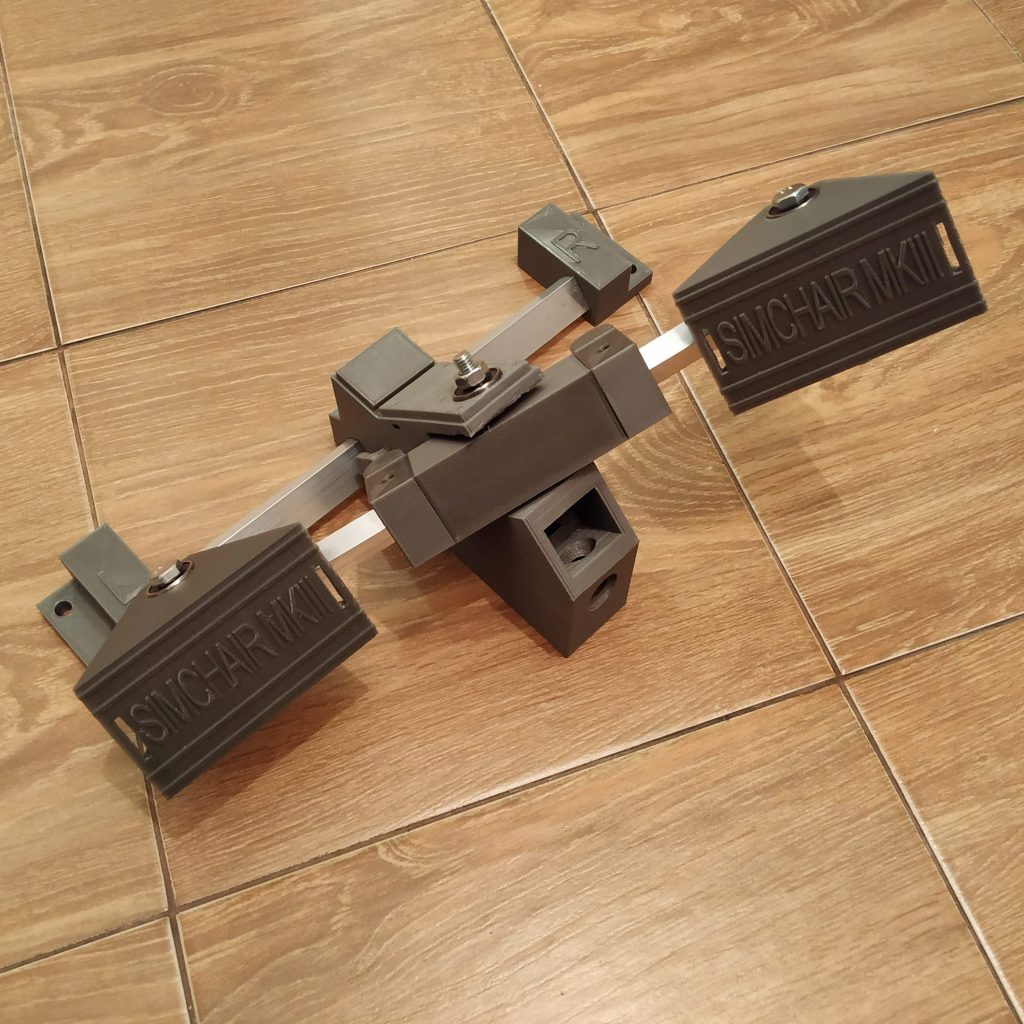
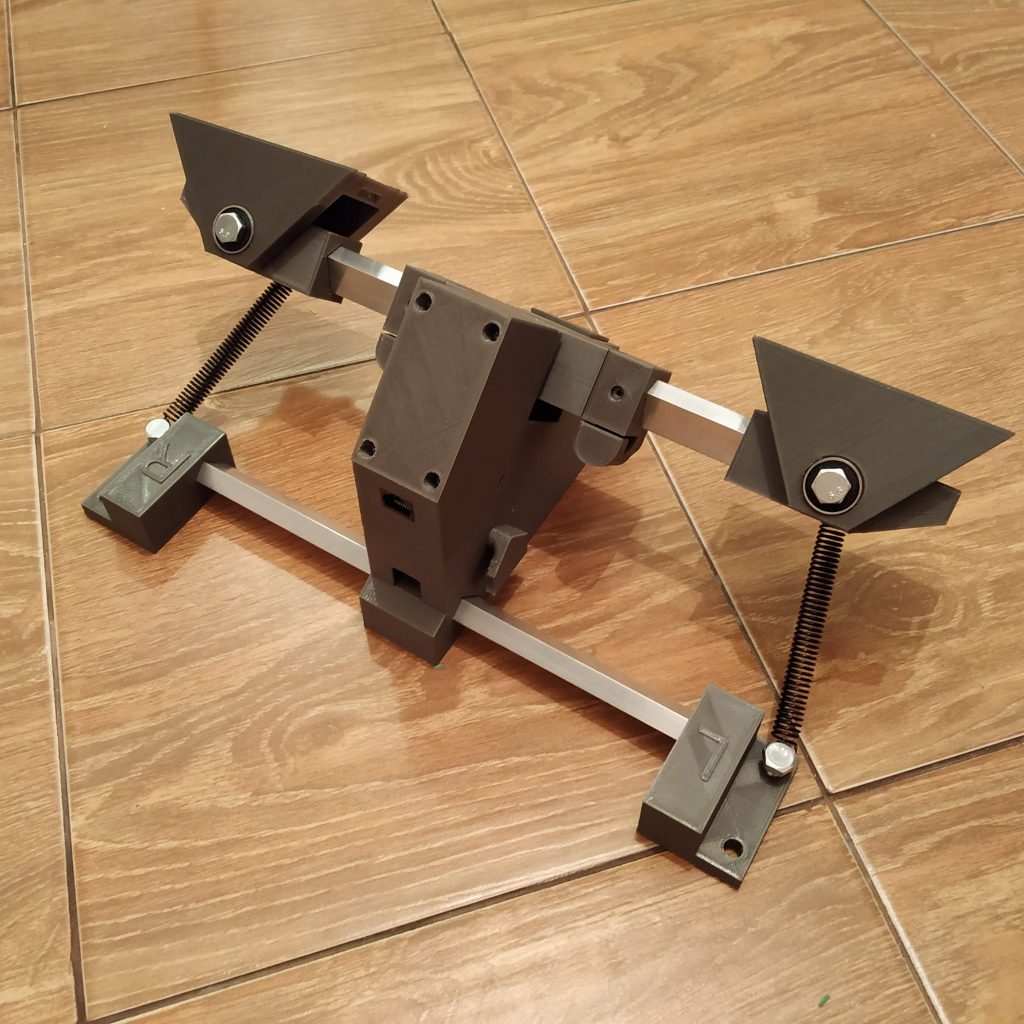
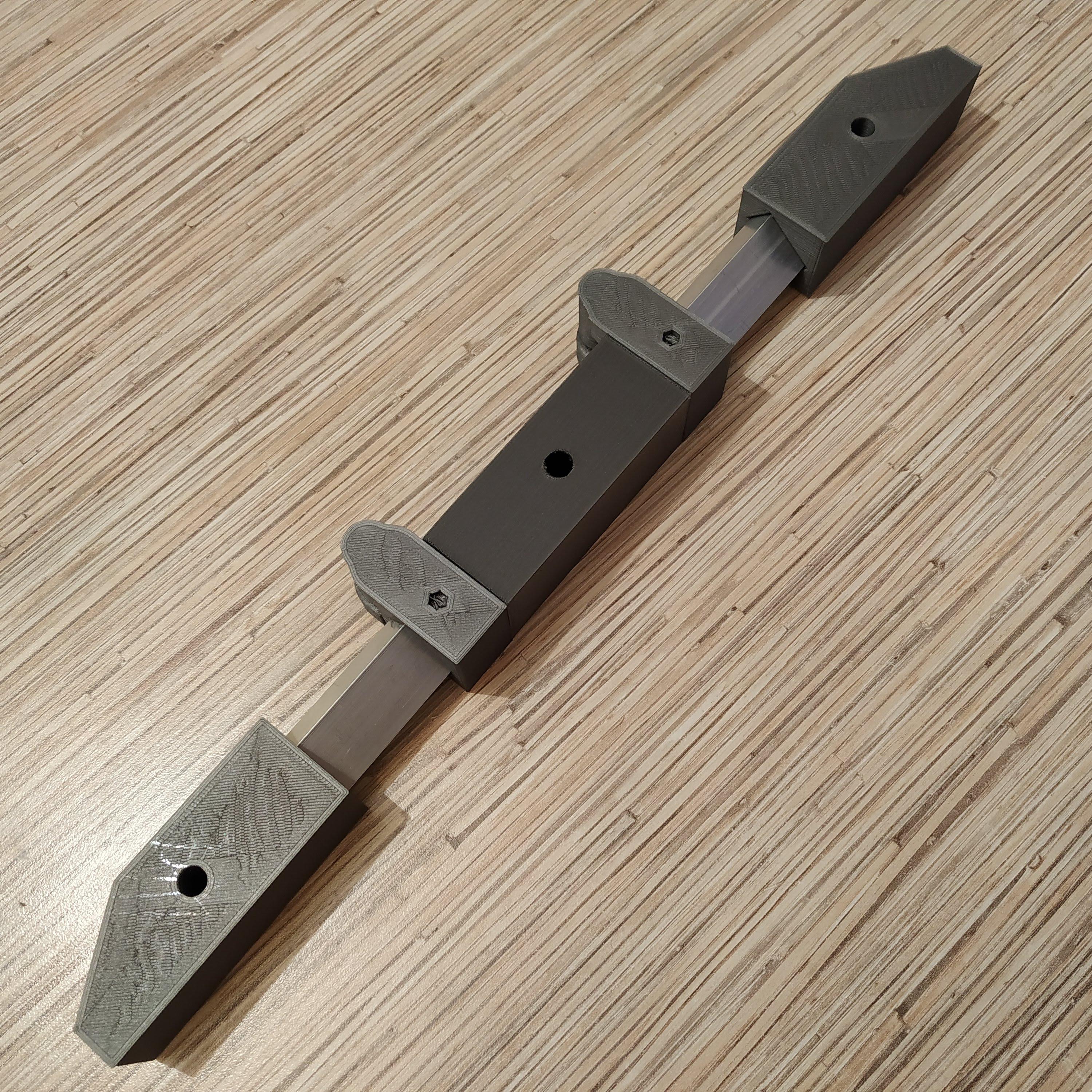
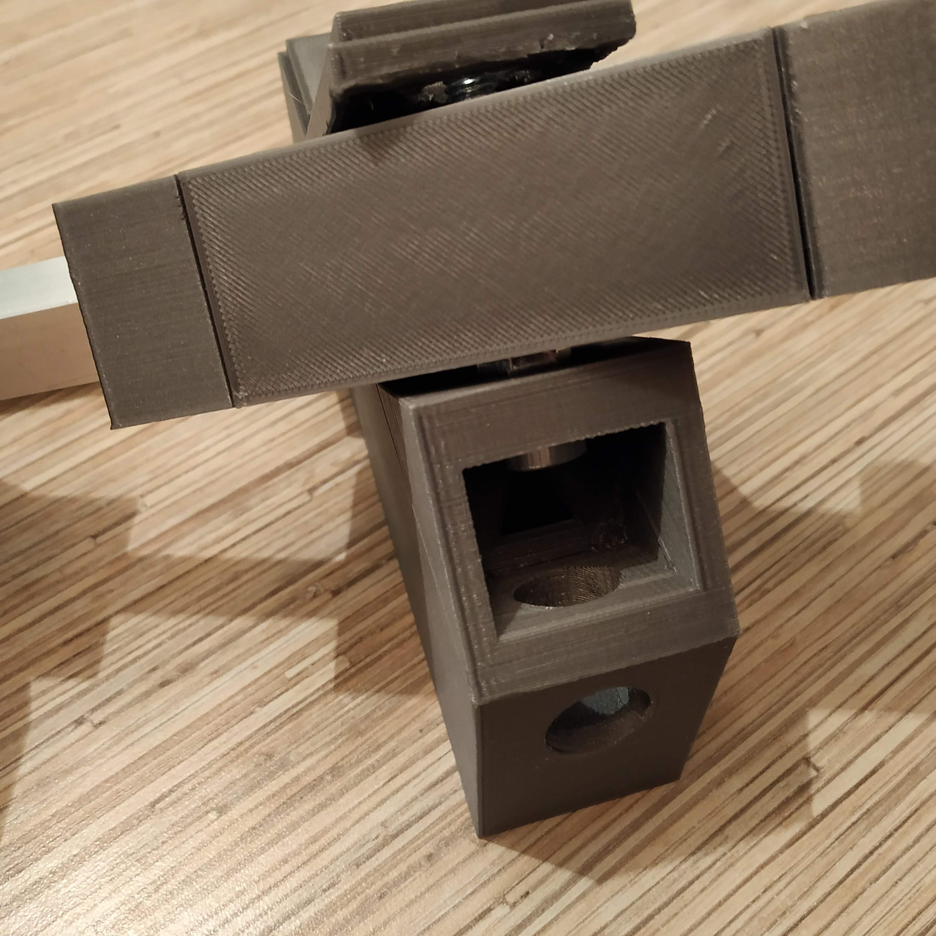
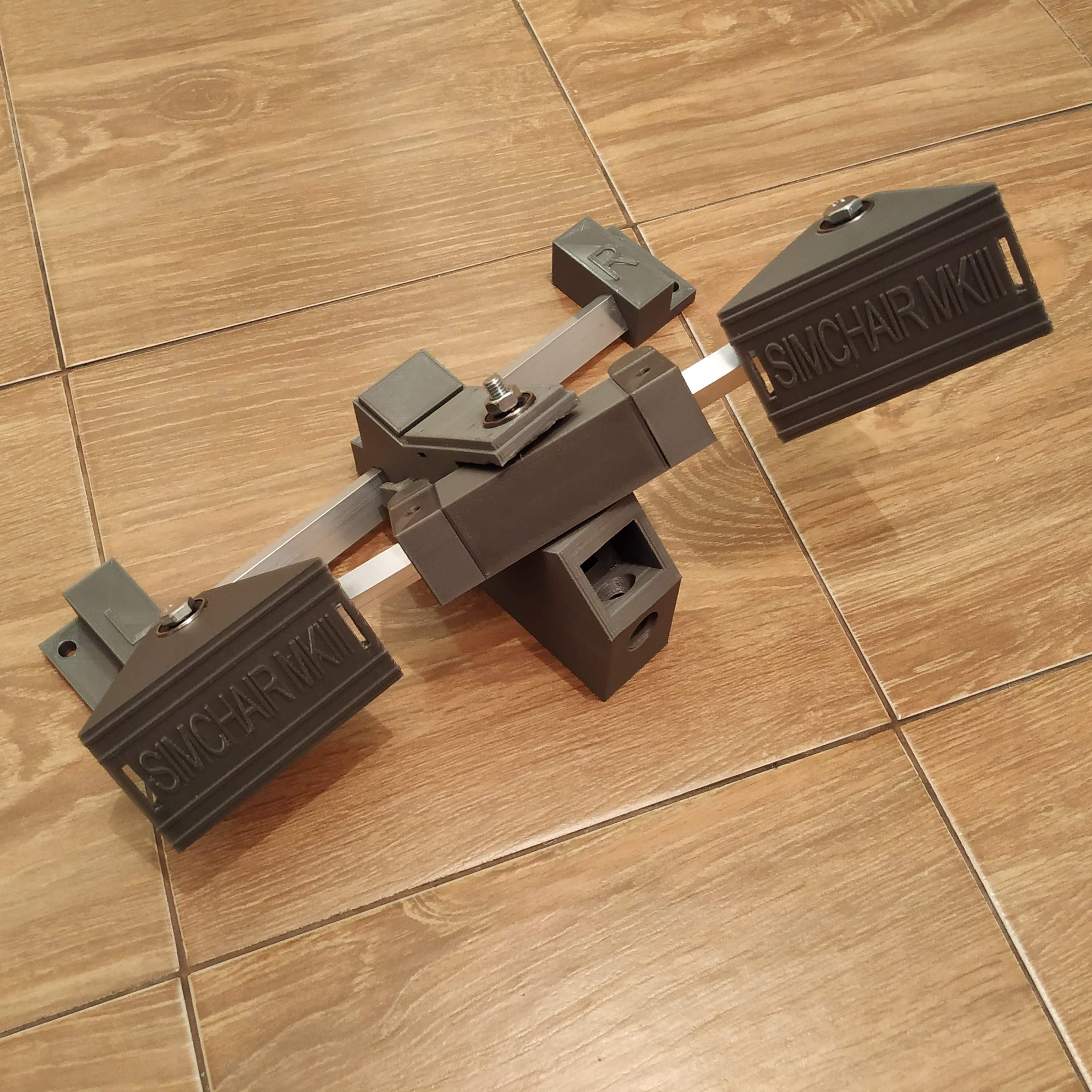
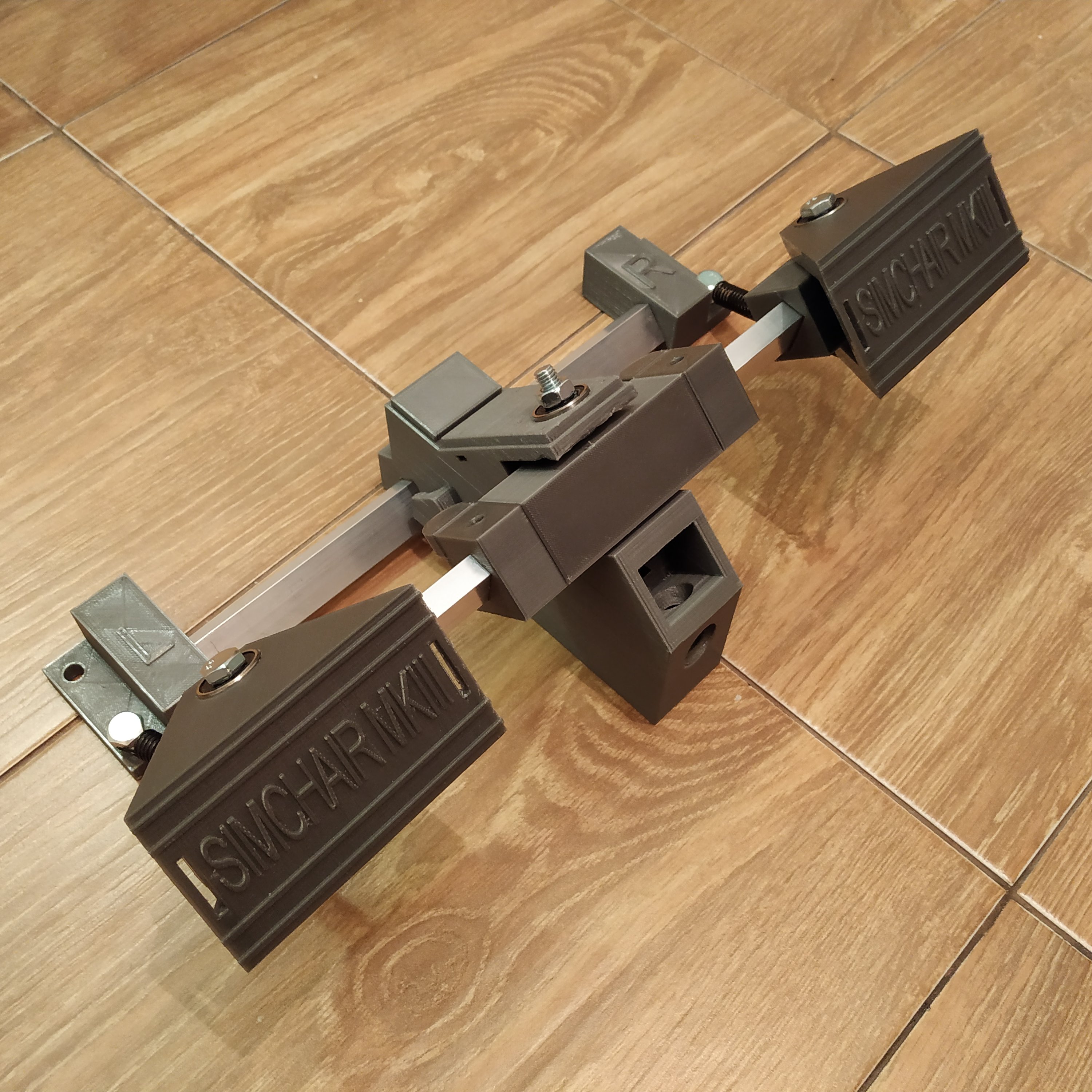
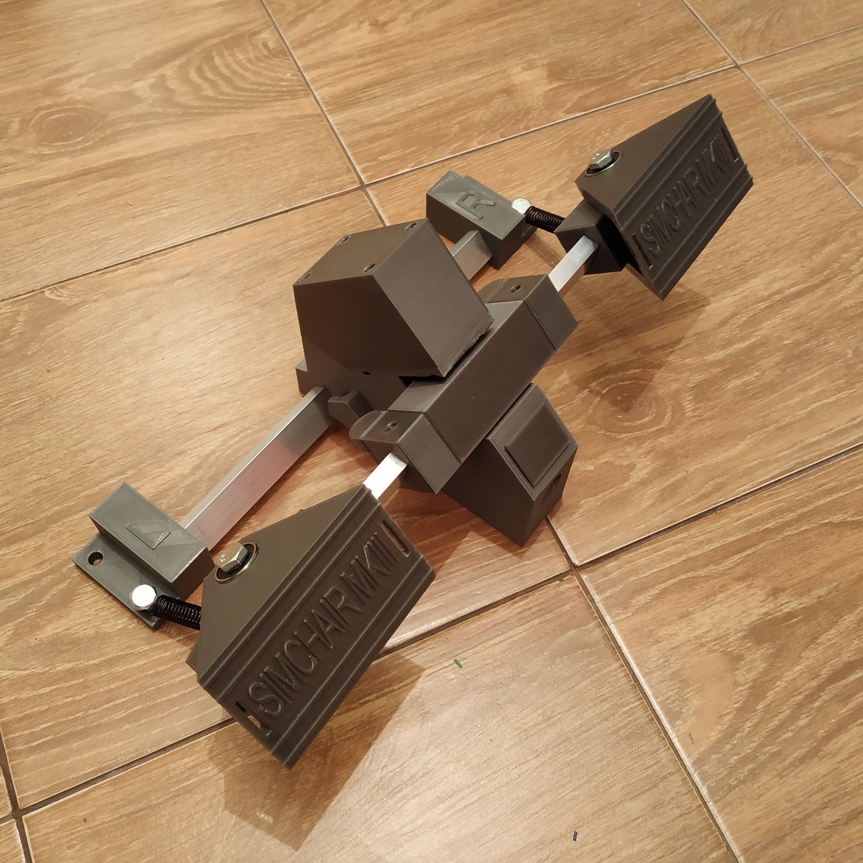
- Repeat steps 8-11 for the 2nd pedal. After you’ll finish, the result should look like that:
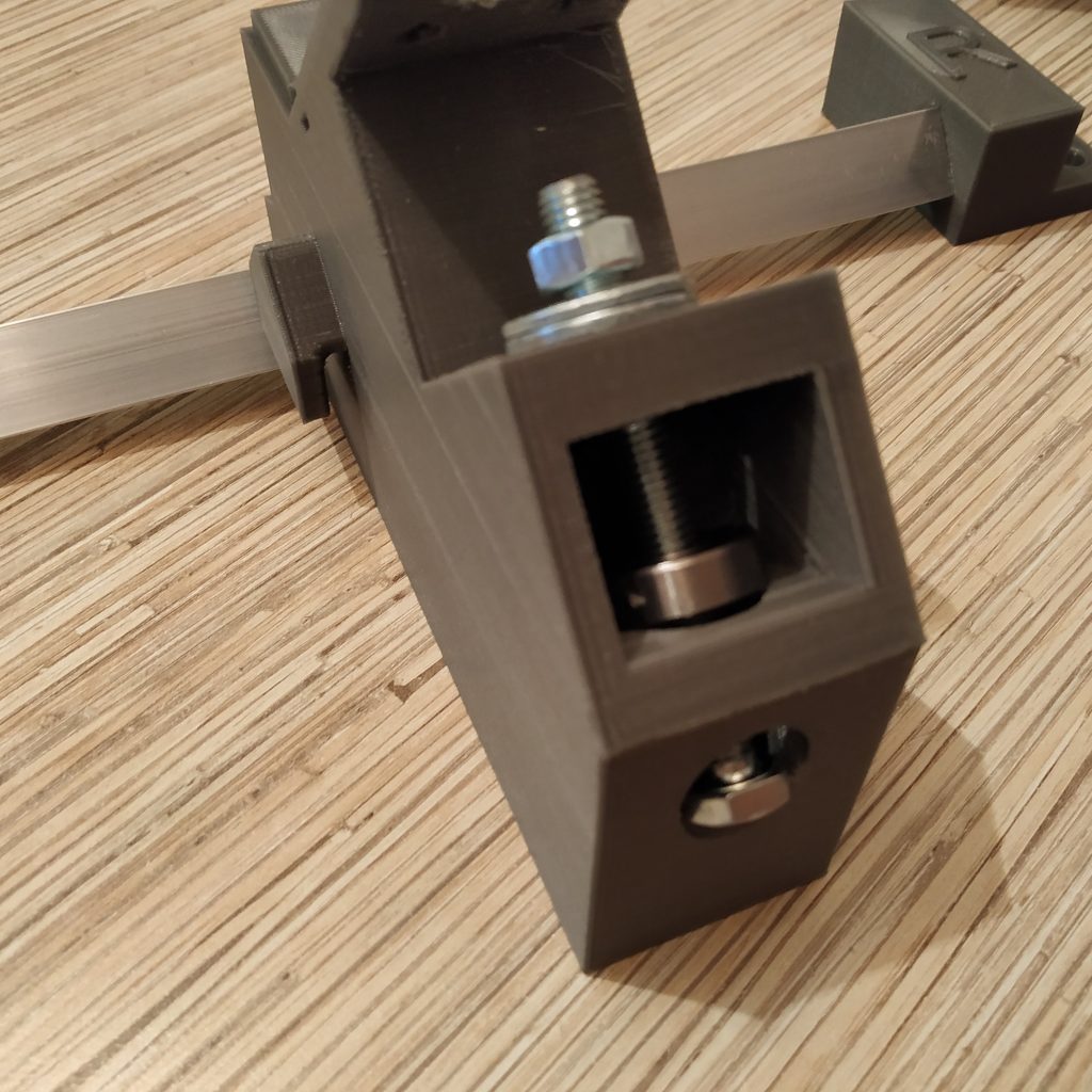
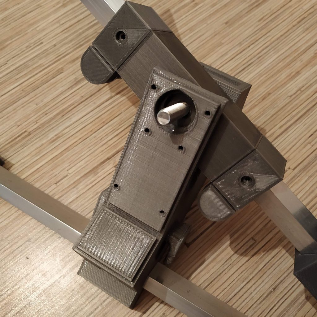
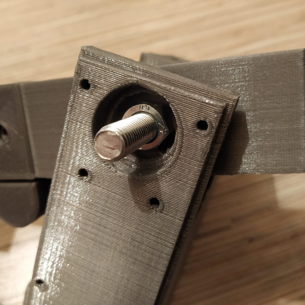
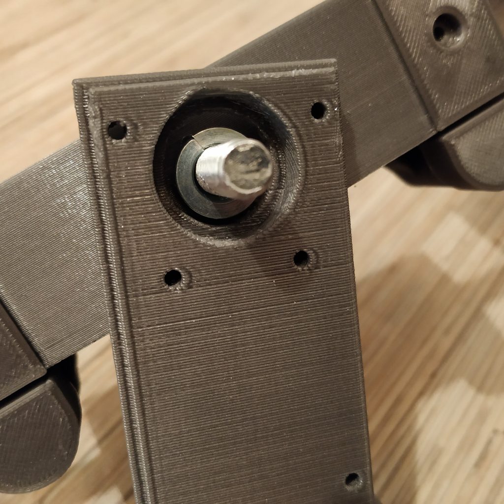
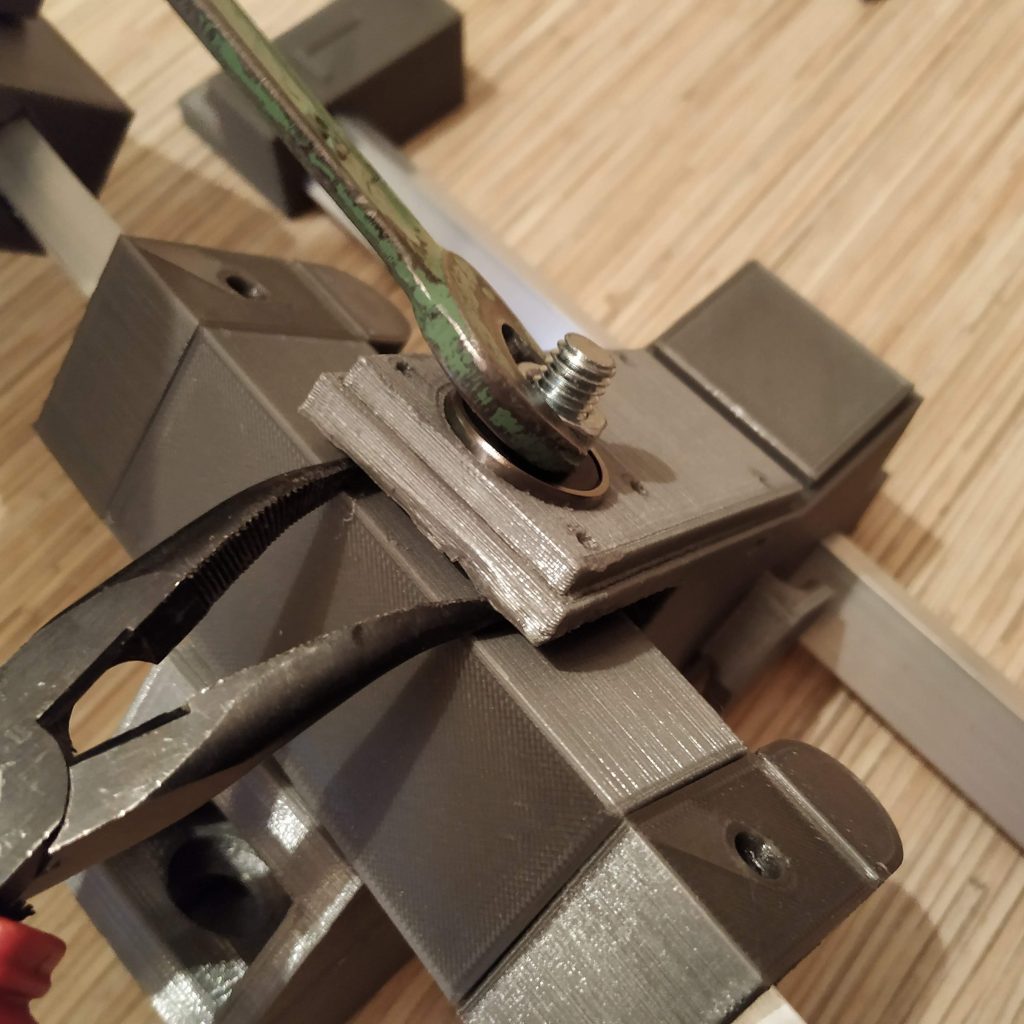
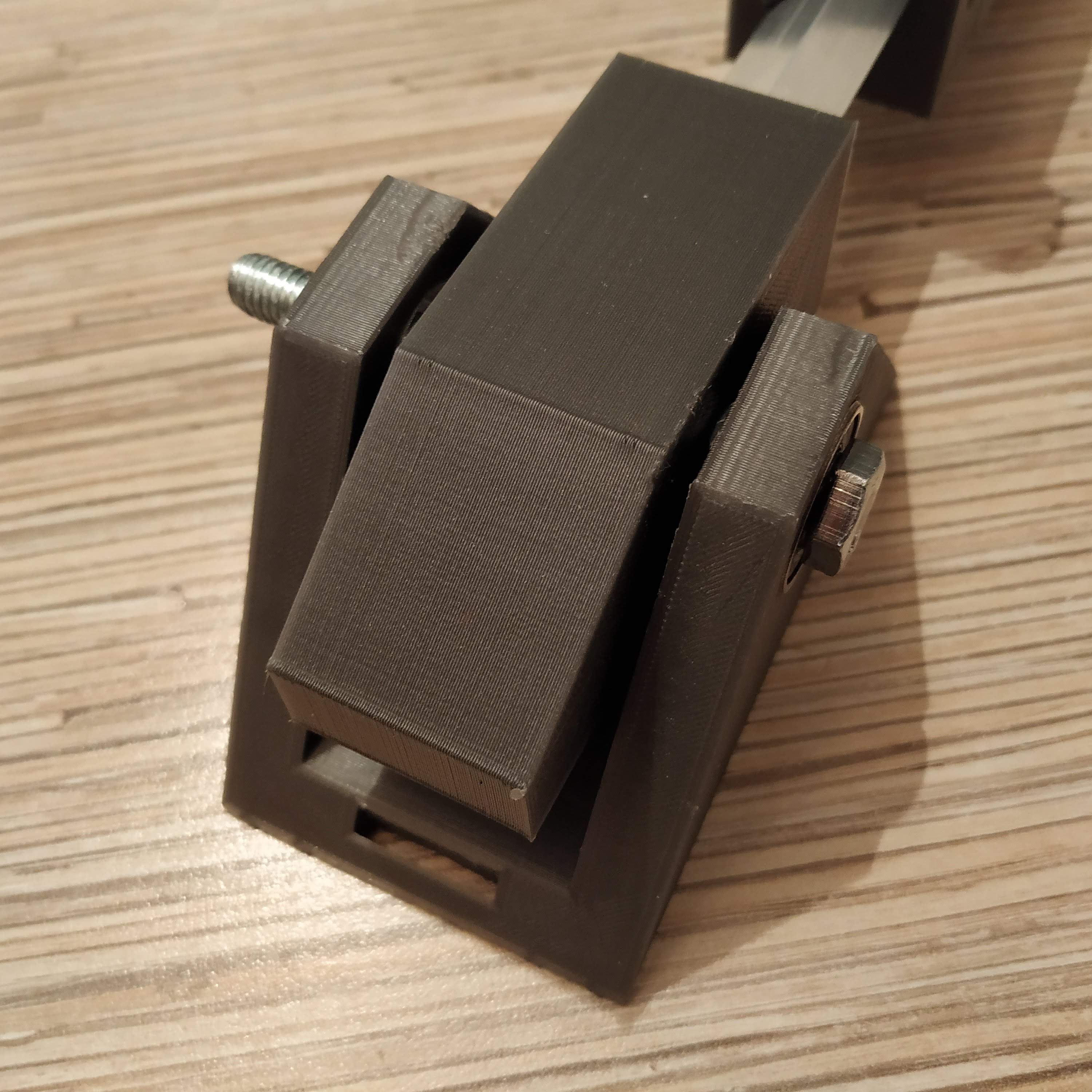
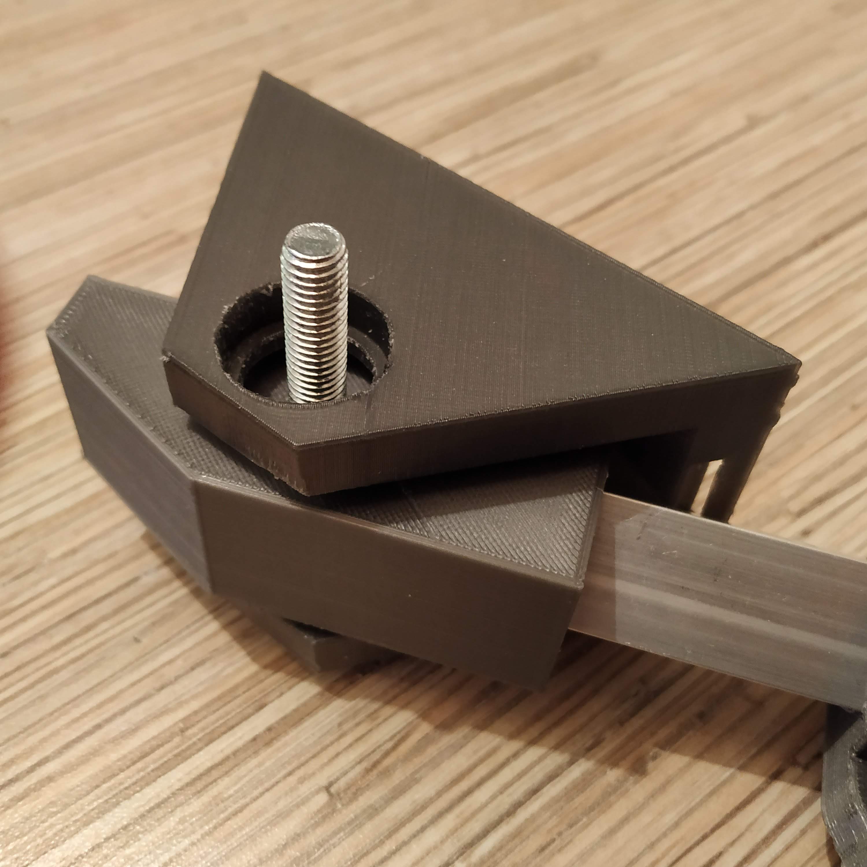
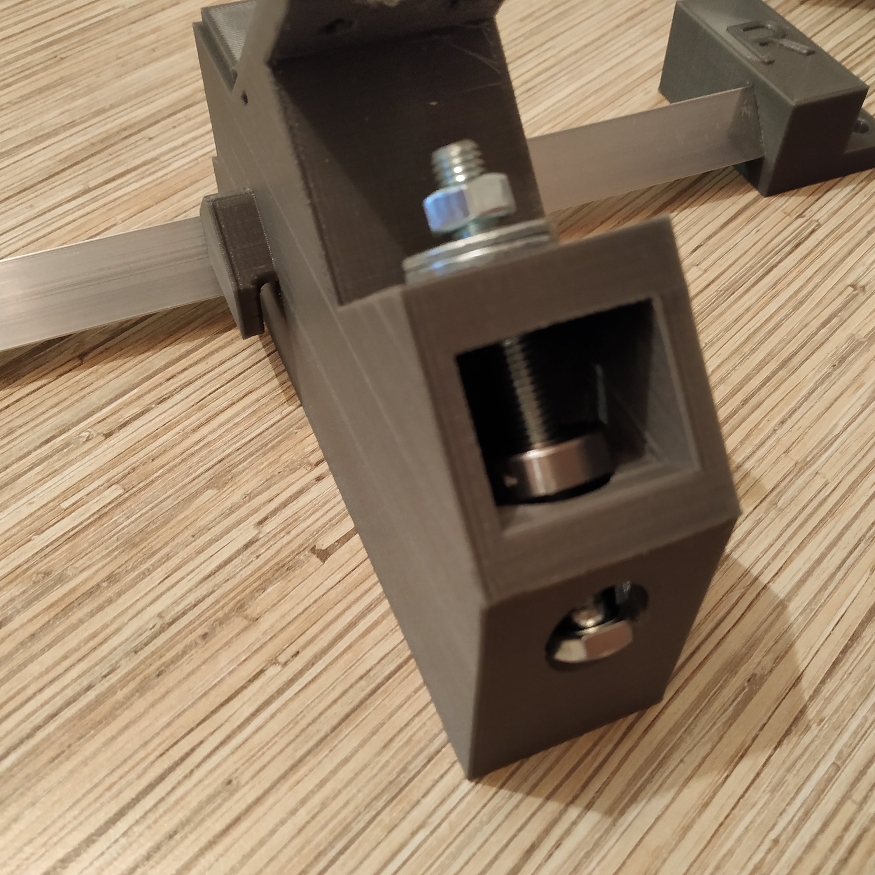
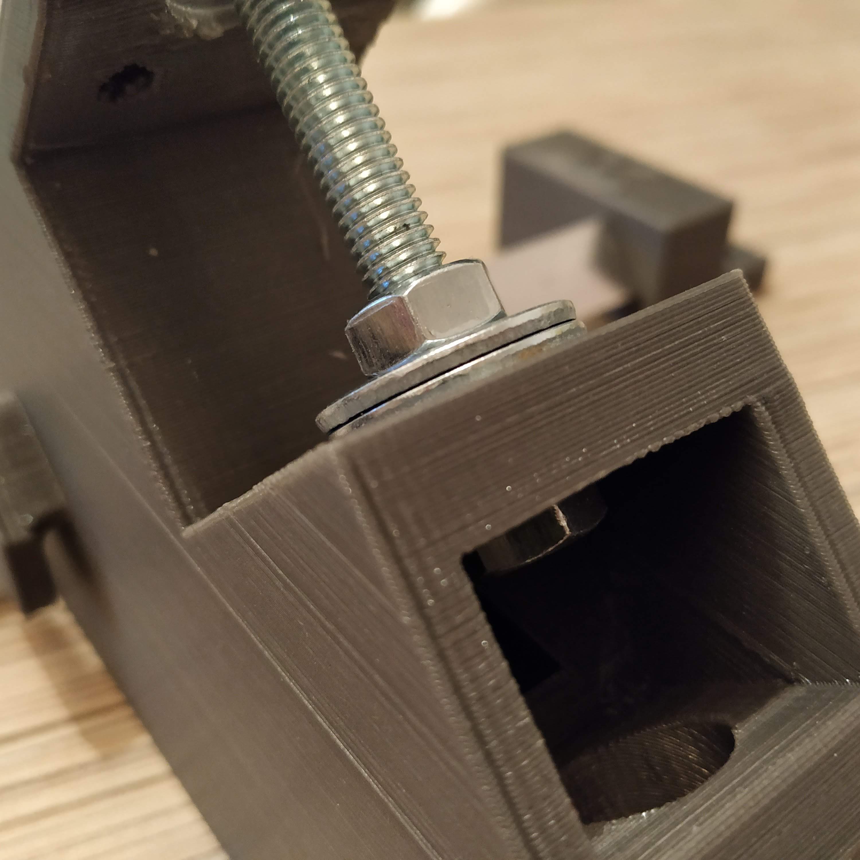
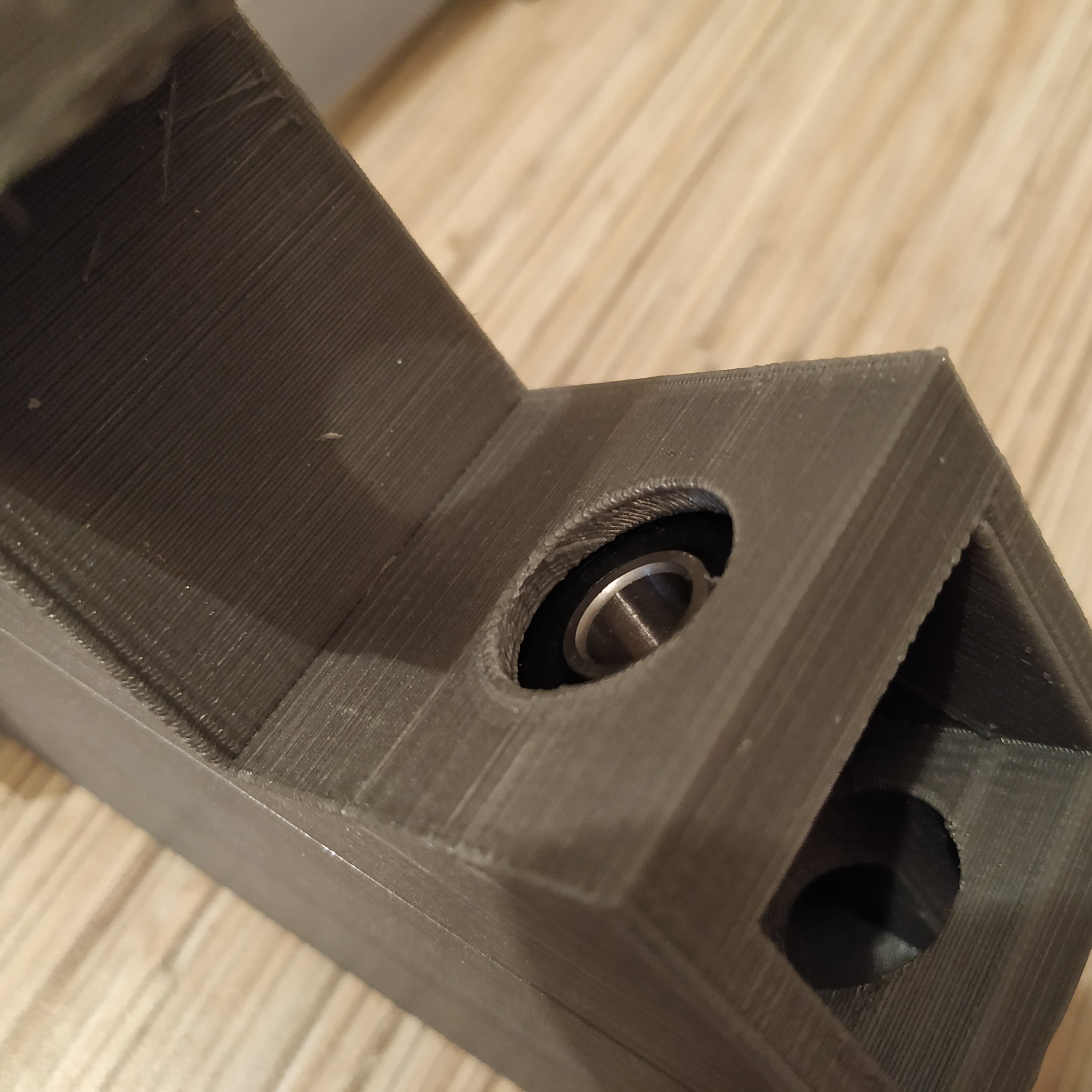
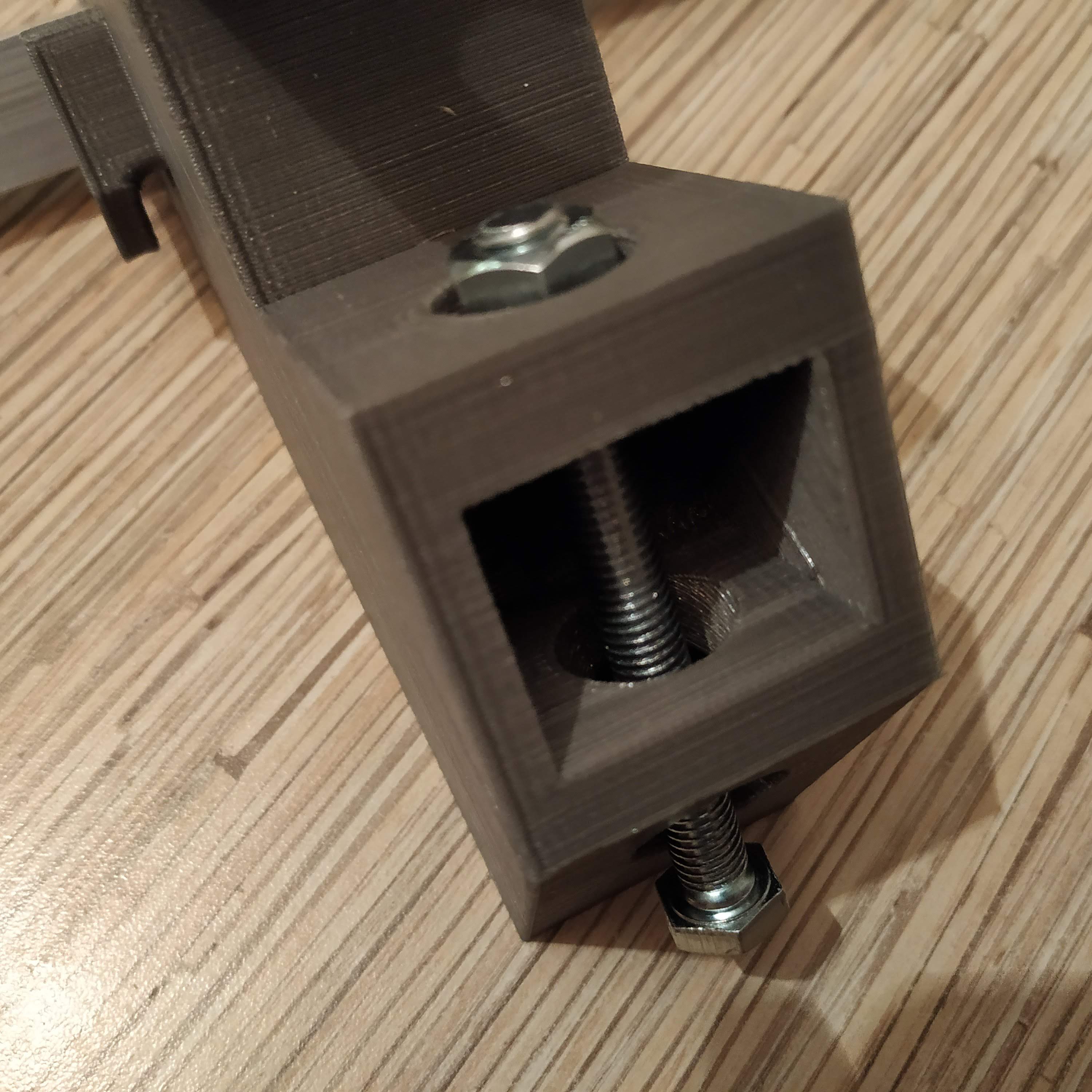
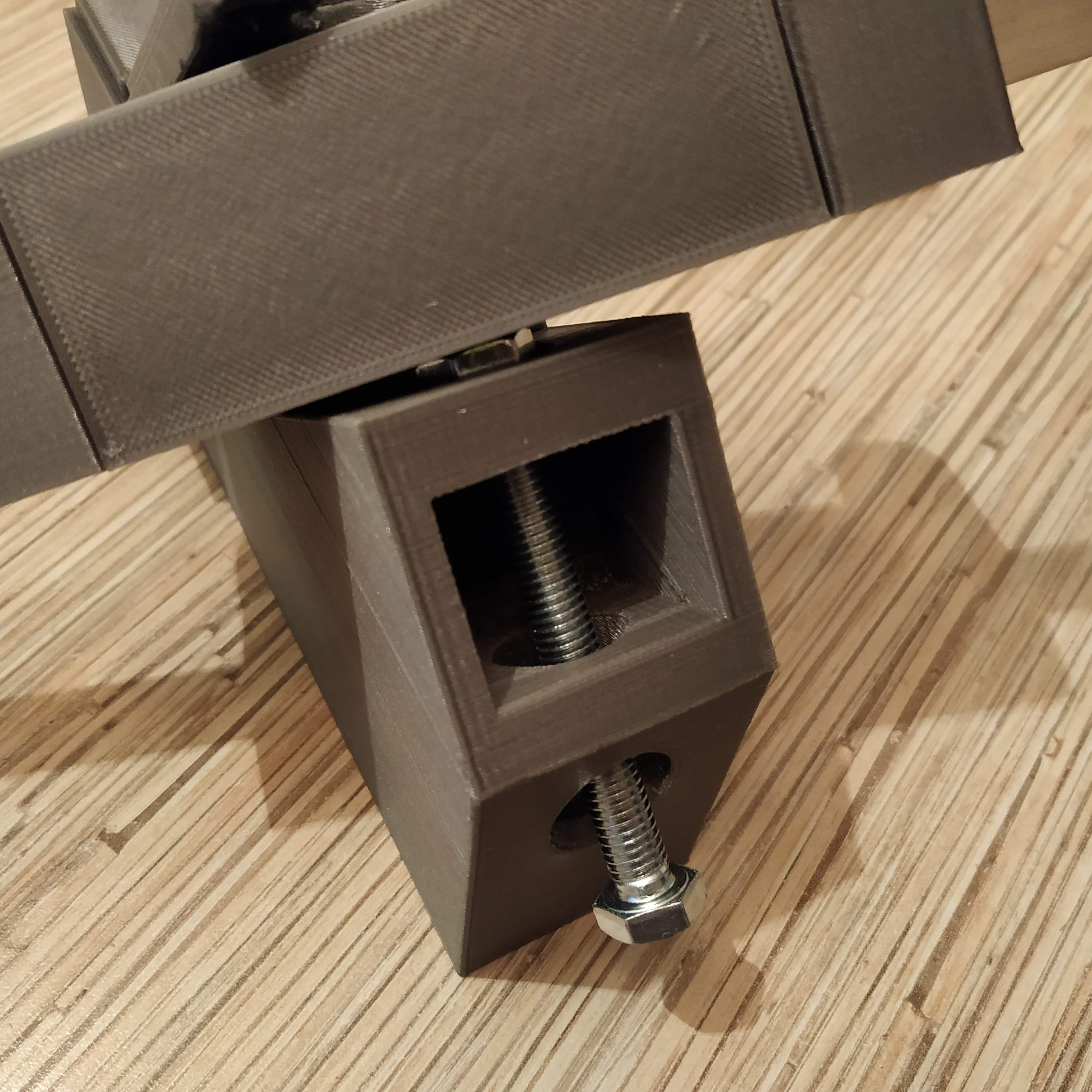
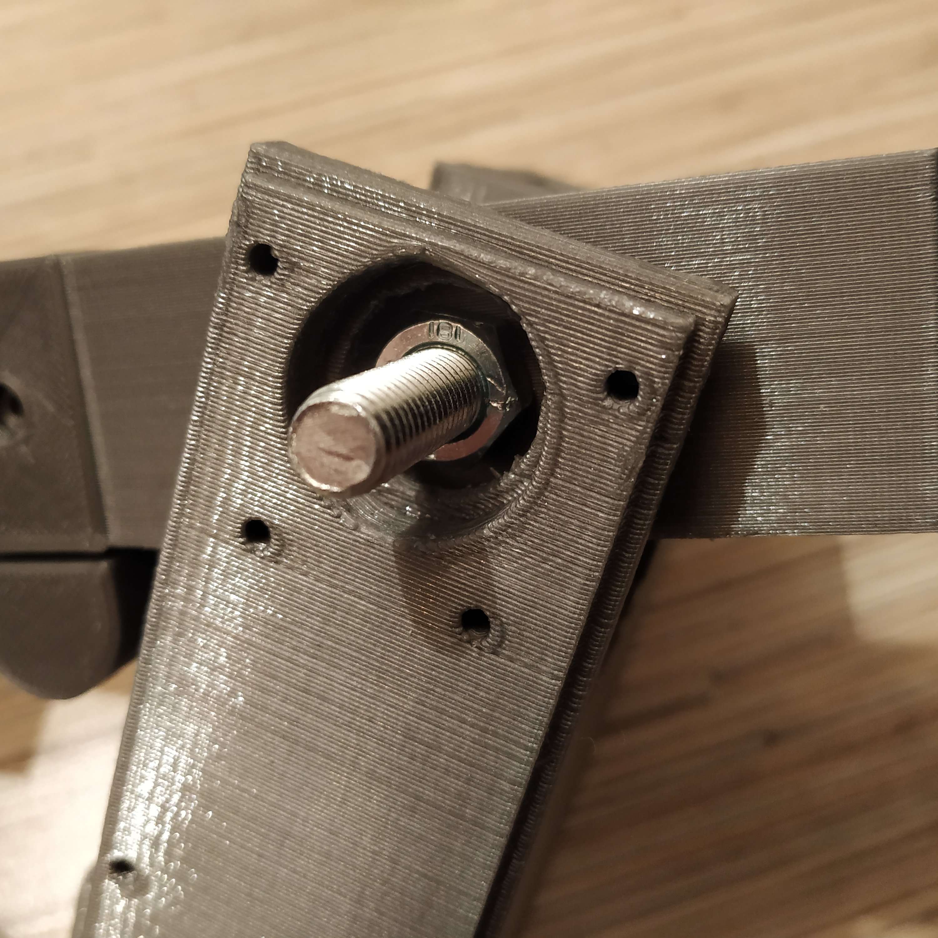
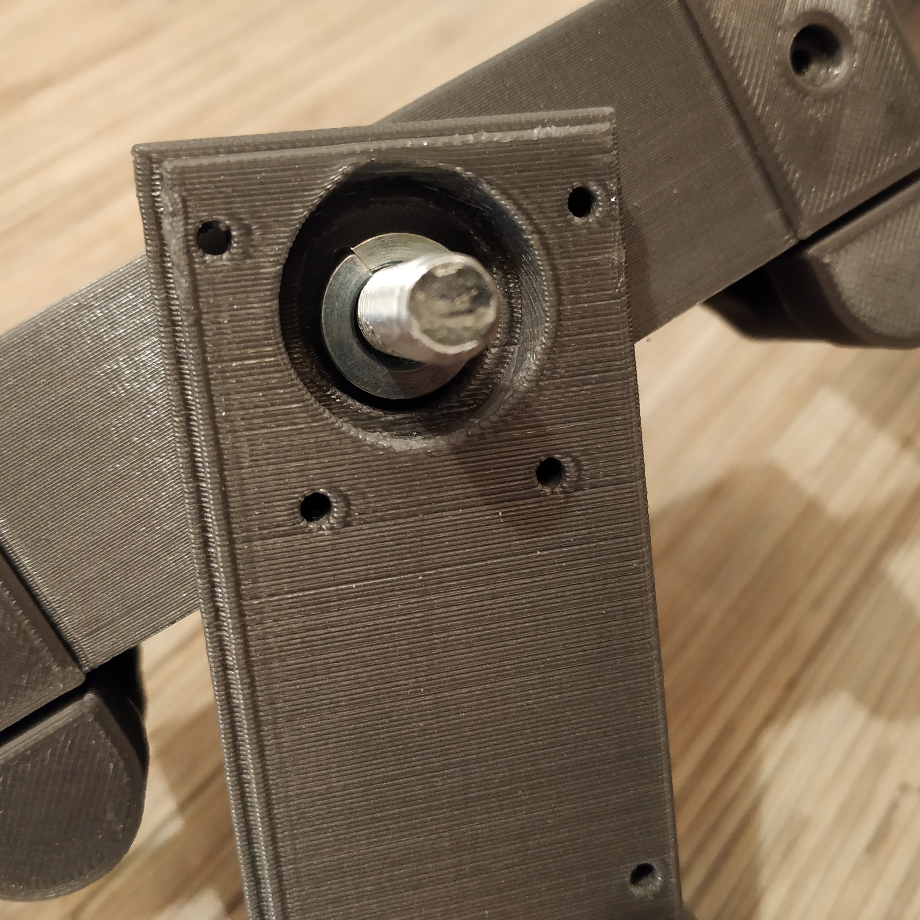
- Press-fit the lower bearing of the main frame into its slot. To do it, use a 3rd M8x75mm bolt, 2 reinforced M8 washers, and a nut, as shown in the pictures below:


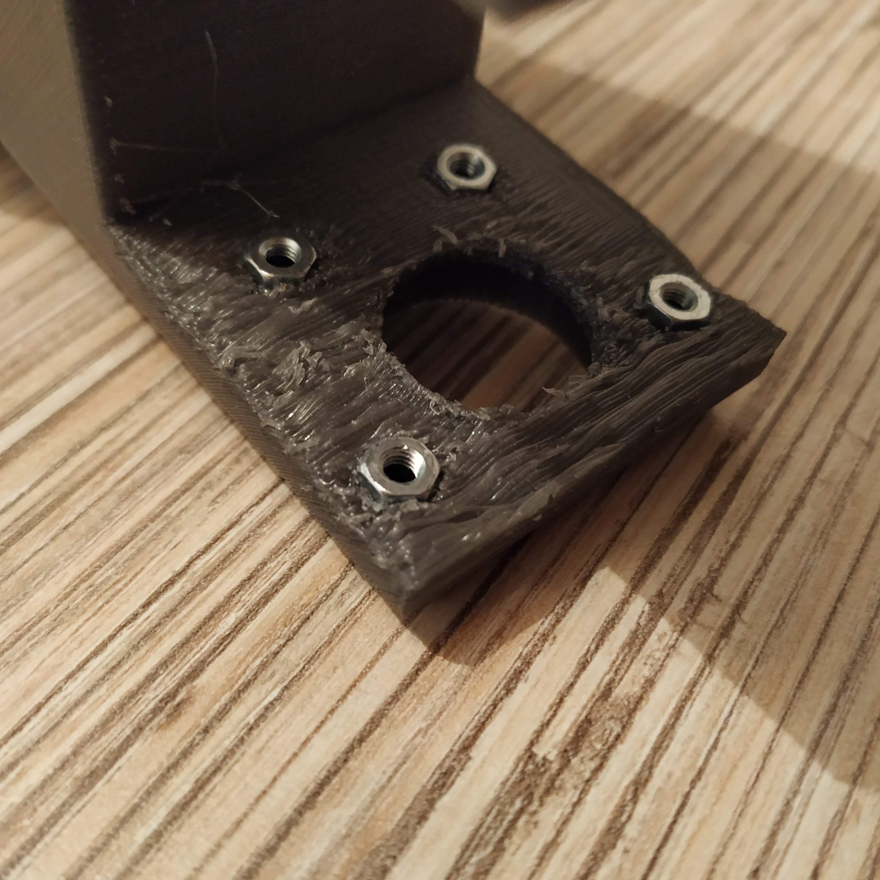
- Press-fit M3 nuts into their slots in the frame.

- Put a bolt through the bearing we have just installed, add a nut and put the rocker assembly on.


- Put a nut onto the bolt and tighten it, add a spring washer.
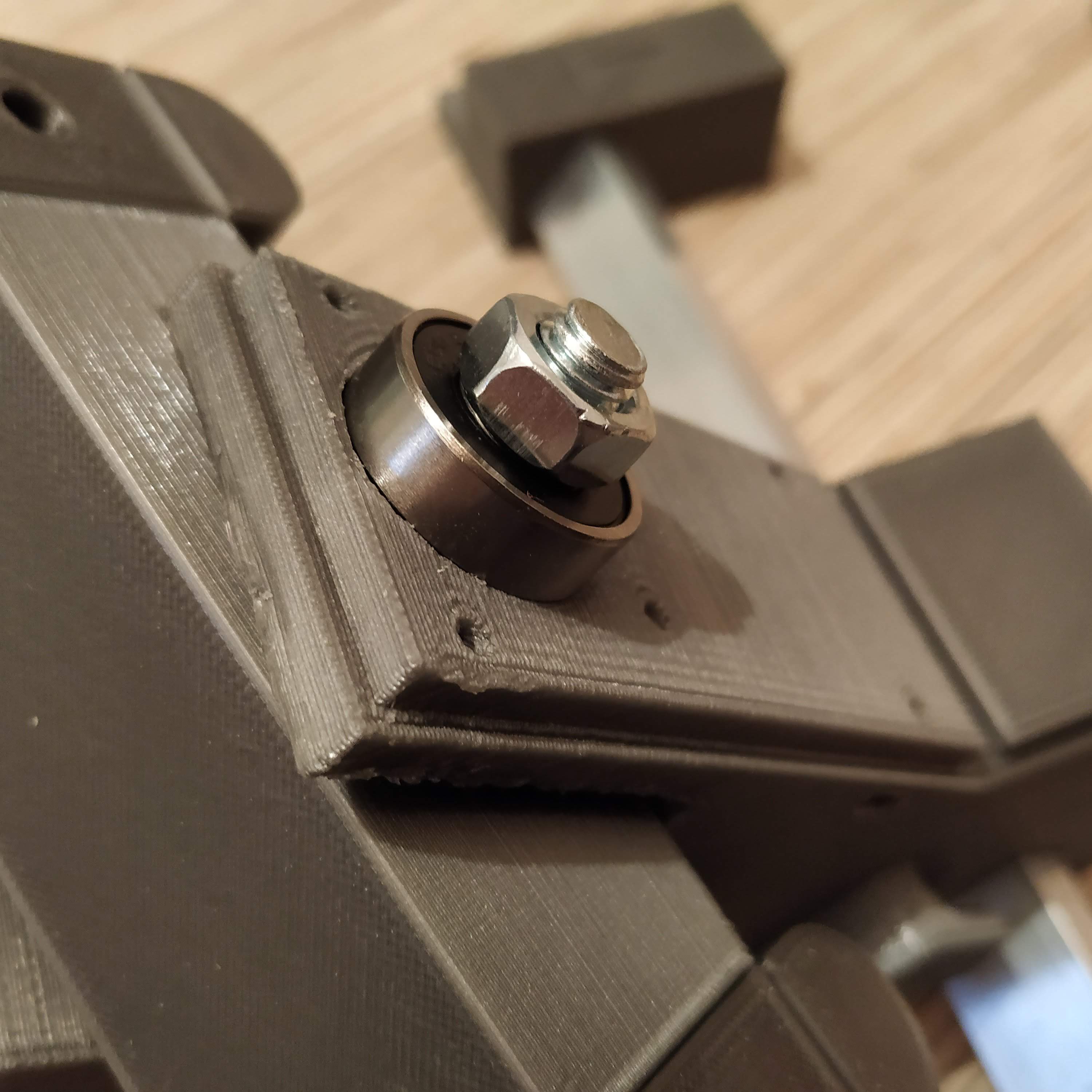
- Put a bearing onto the bolt, add a nut and tighten it firmly, press-fitting the bearing into its slot. Put something between the rocker and the frame so the frame won’t bend! Check there’s no backlash in the assembly.
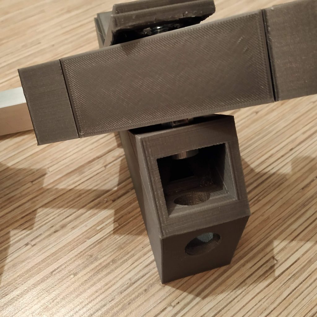
Our progress at this point:
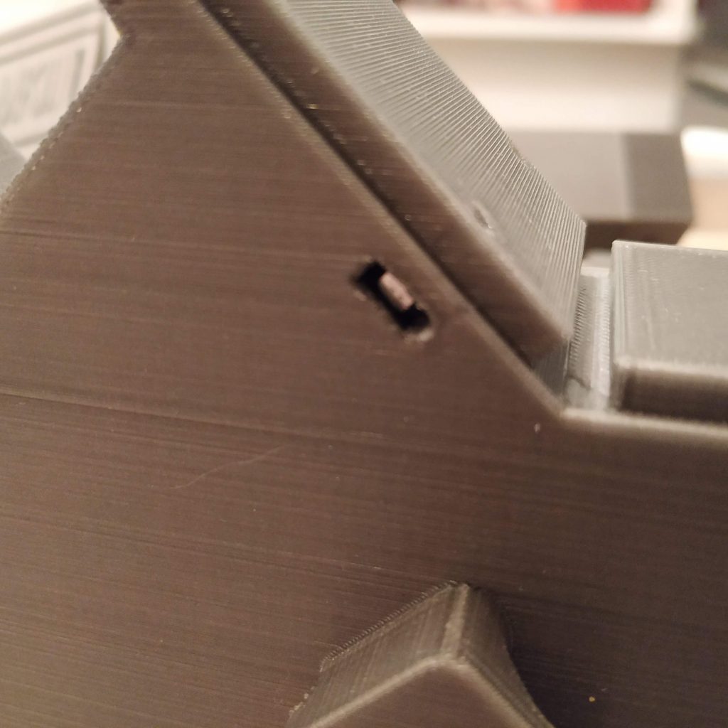
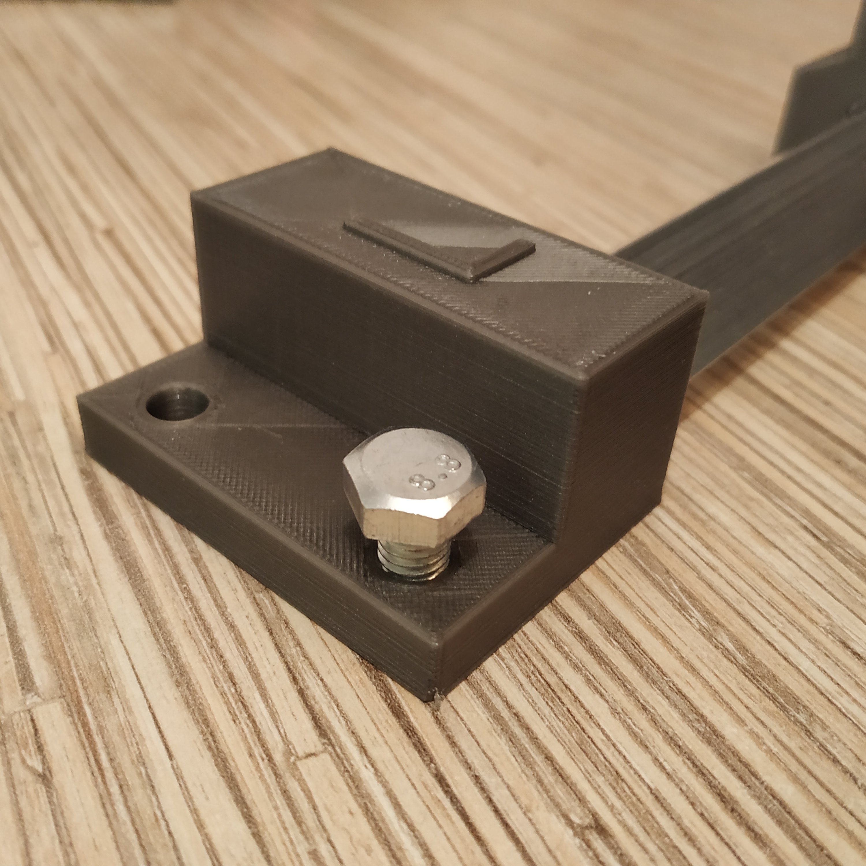
- Insert 2 M8x16mm bolts into frame legs as shown in the following picture:

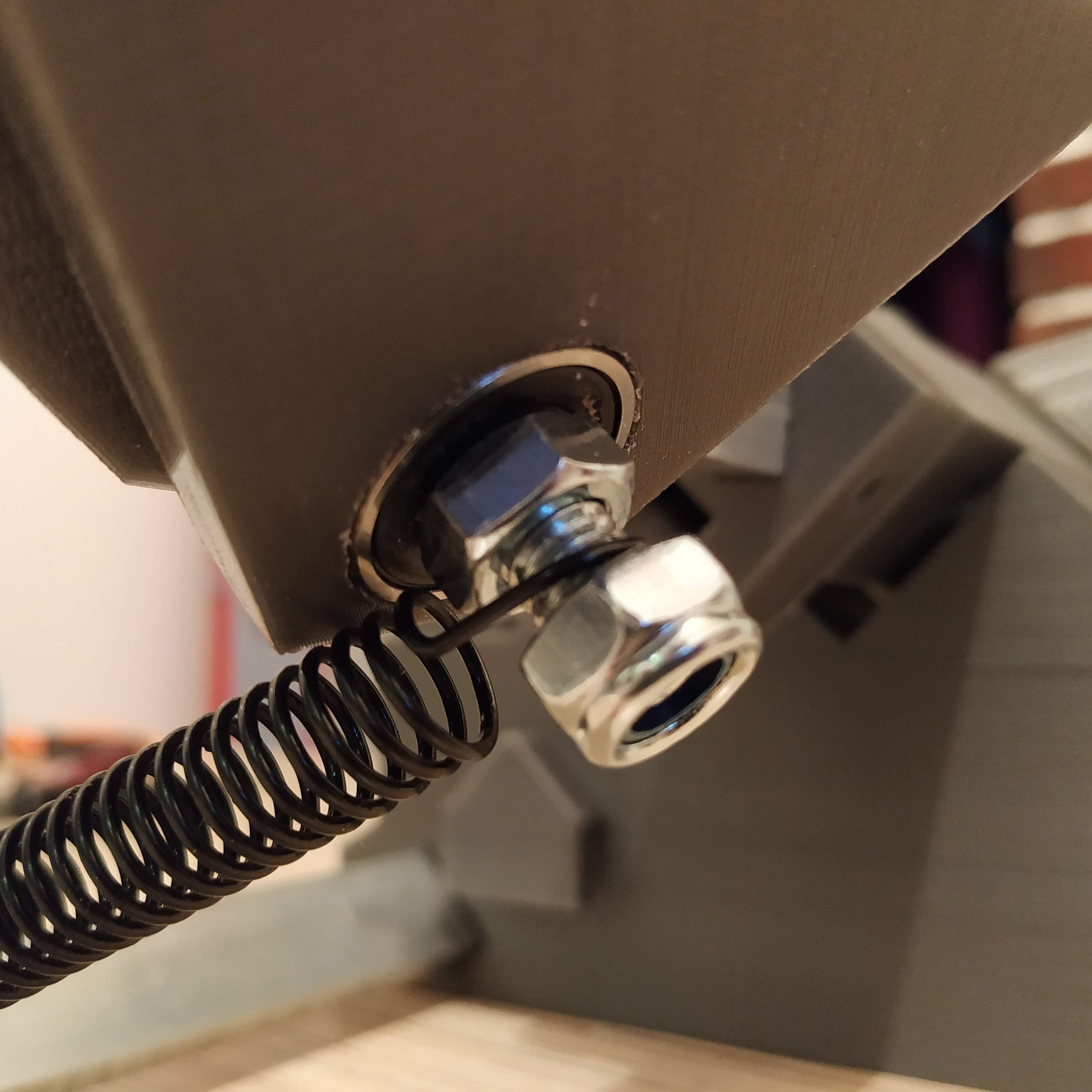
- Put 2 M8 nyloc nuts onto pedal mount bolts:

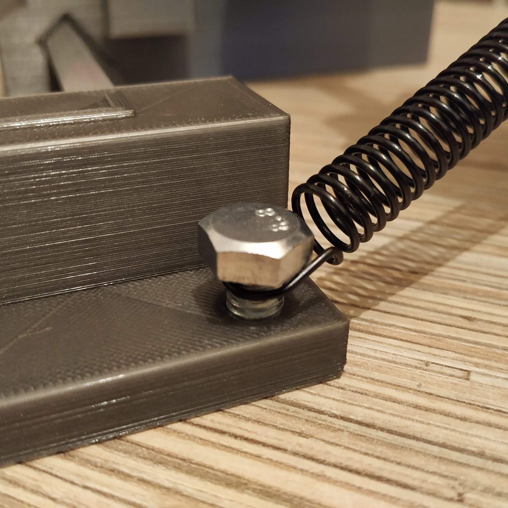
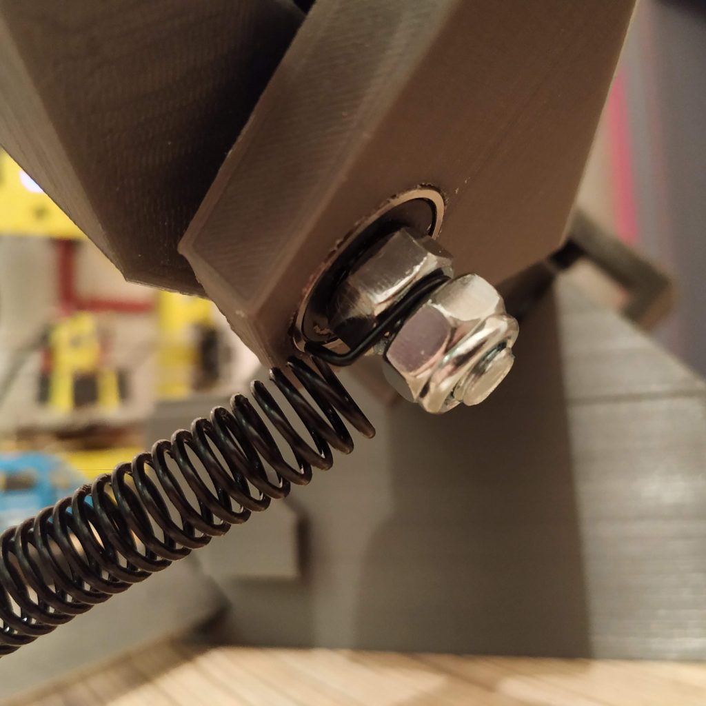
- Put springs on as shown in pictures below and tighten nyloc nuts a bit until they will be barely touching springs, springs should be able to rotate freely. Pedals should be more or less centered now, if they are slightly off the center, do not worry about it too much, you won’t feel it at all.

Progress at this point:

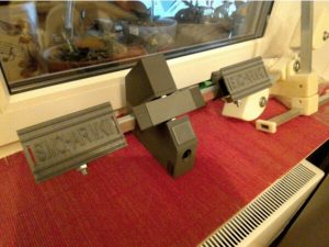
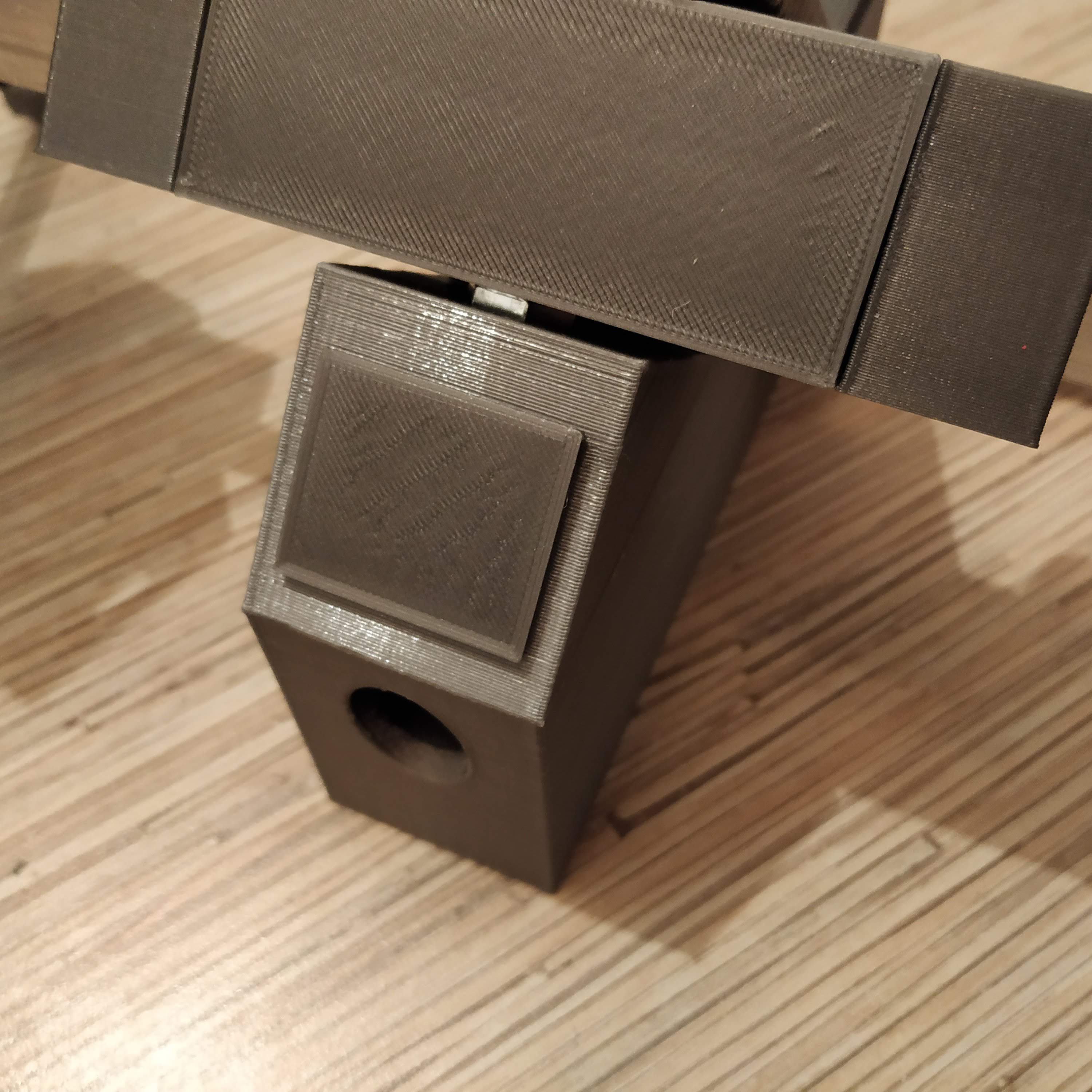
- Press-fit the front cover into its square socket. We have finished the mechanical part of an assembly process. Let’s move on to electronics!

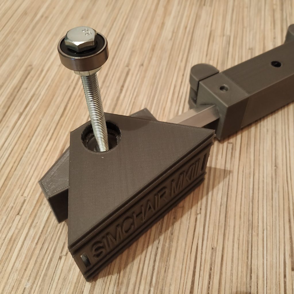
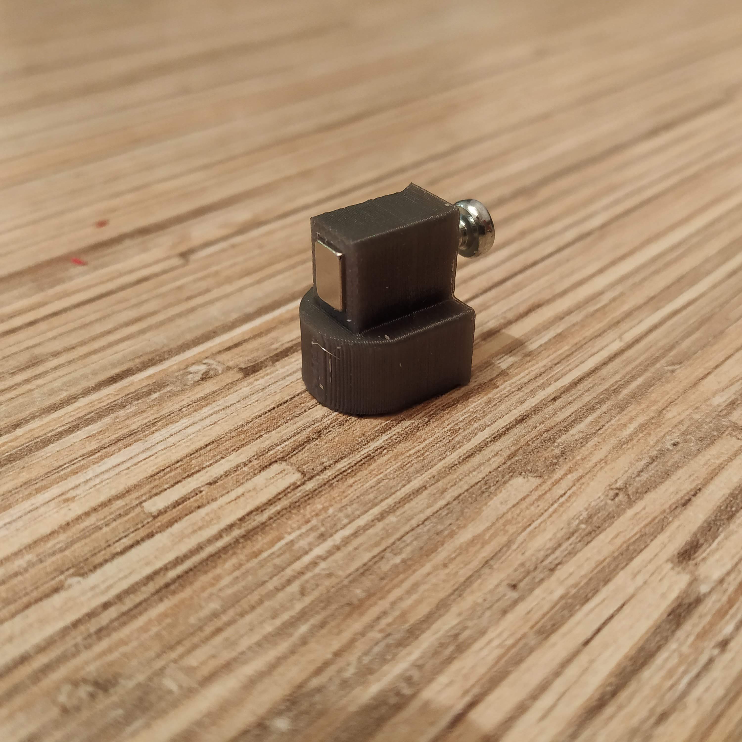
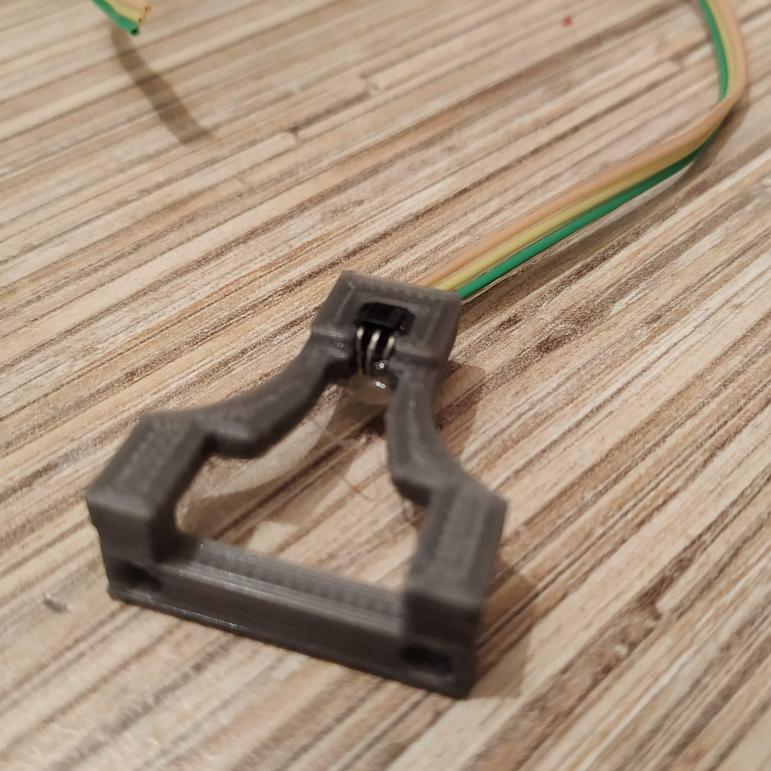
- Put a magnet into a magnet holder. Insert an M3x6mm screw into the hole in the rear wall of the holder and tighten it until it touches the magnet.
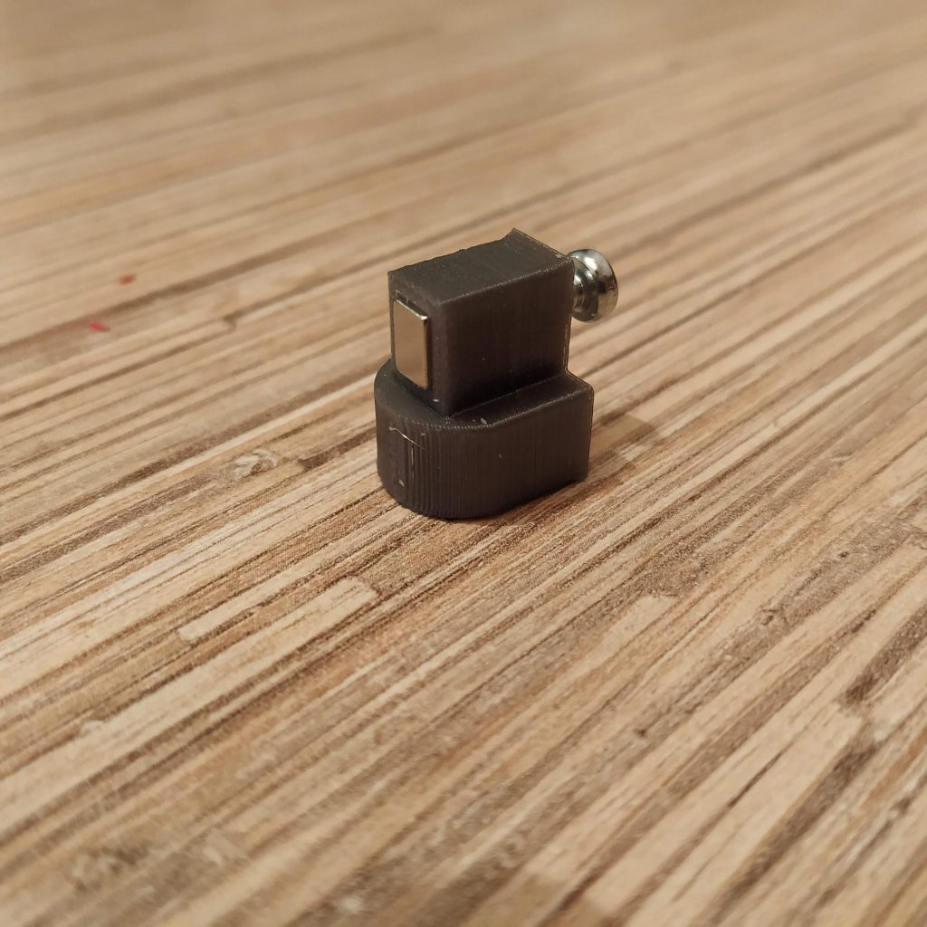
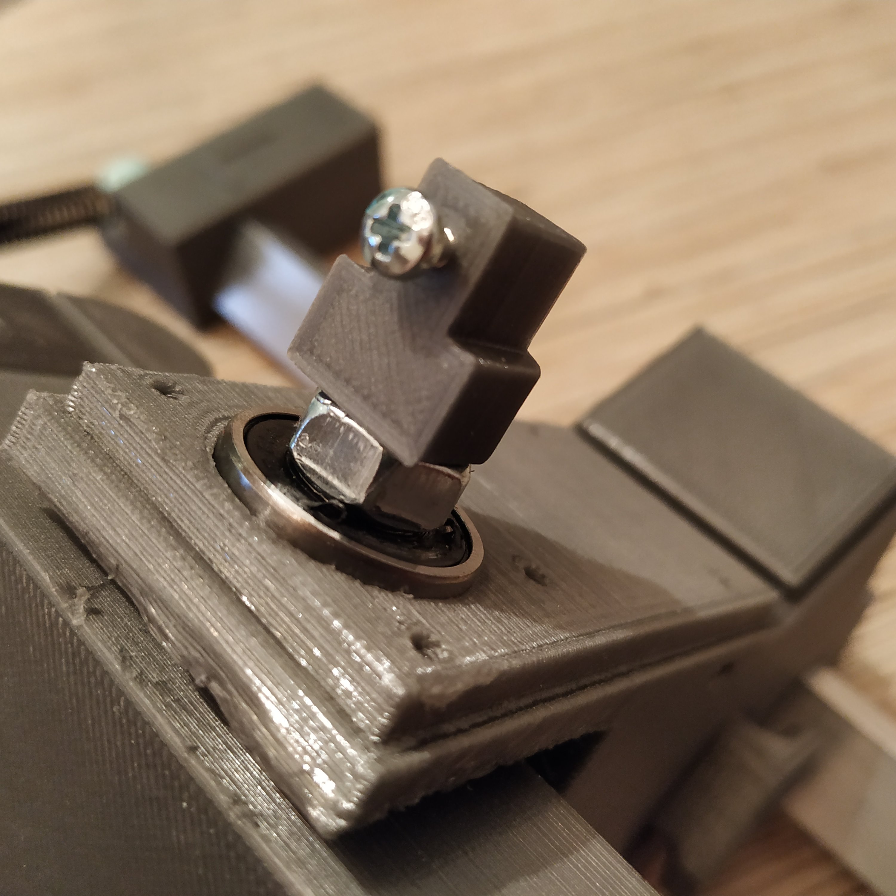
- Put the magnet holder onto the main axis bolt of pedals.

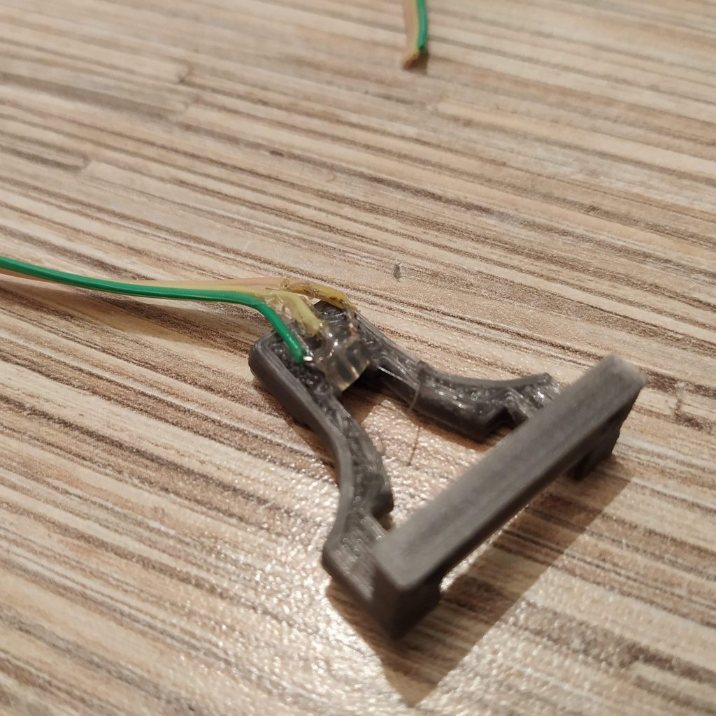
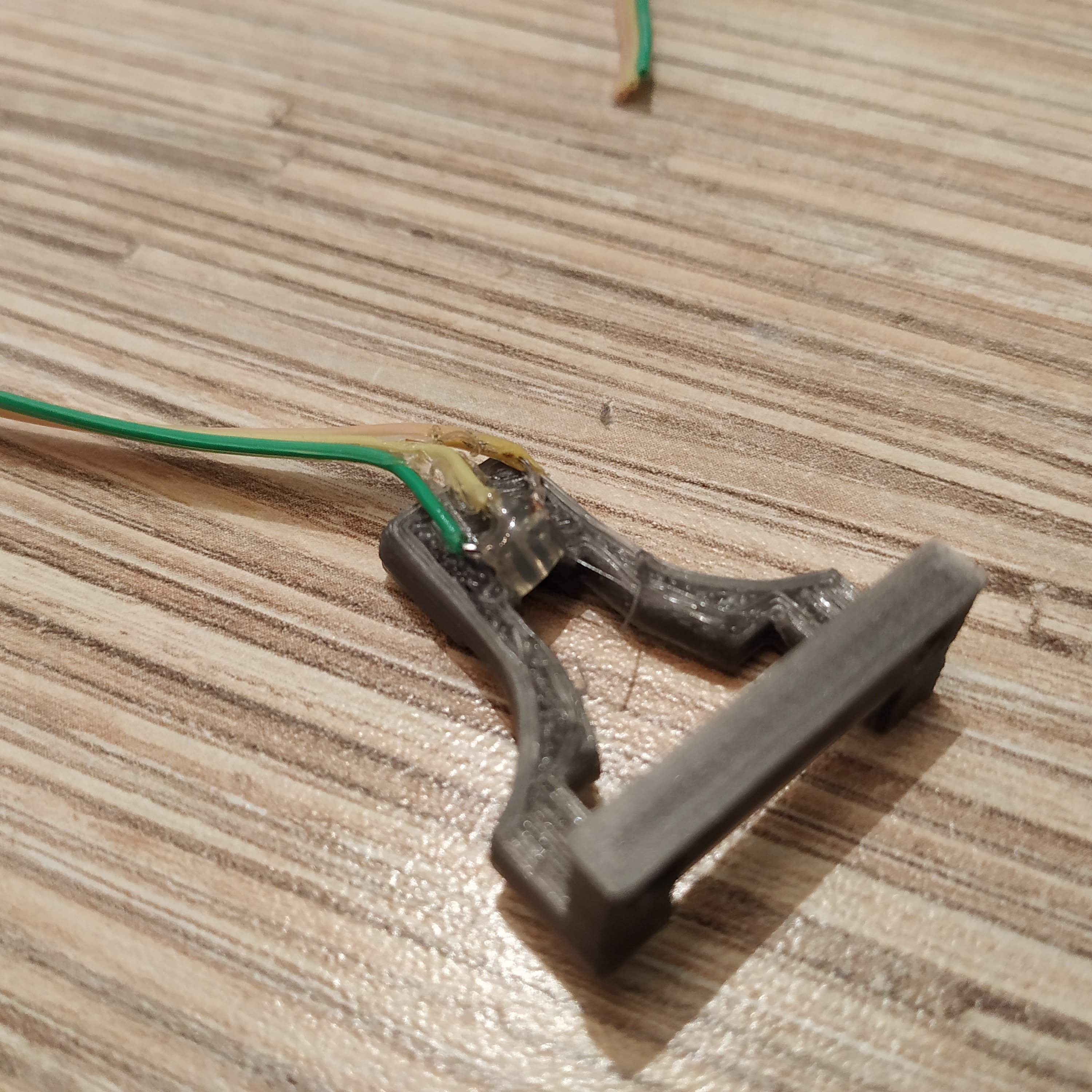
- Cut a 3-wire cable off the ribbon and solder it to a SS495A1 sensor.
- Press-fit the sensor into its socket, add a drop of superglue to fix it in place, and a drop of hot glue to fix legs of the sensor and prevent them from touching each other.

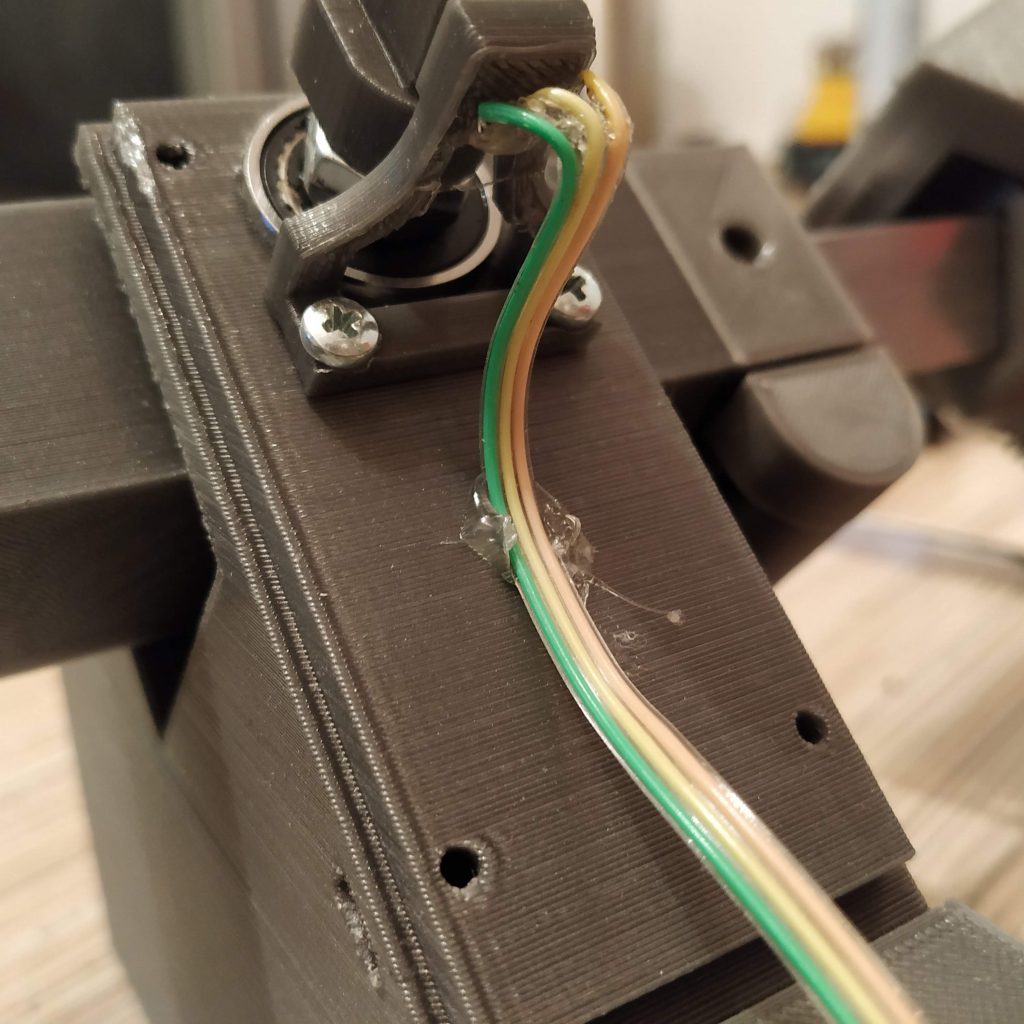
- Put the sensor holder onto the frame and fix with 2 M3x16mm screws. Fasten the sensor cable to the frame with a drop of hot glue.
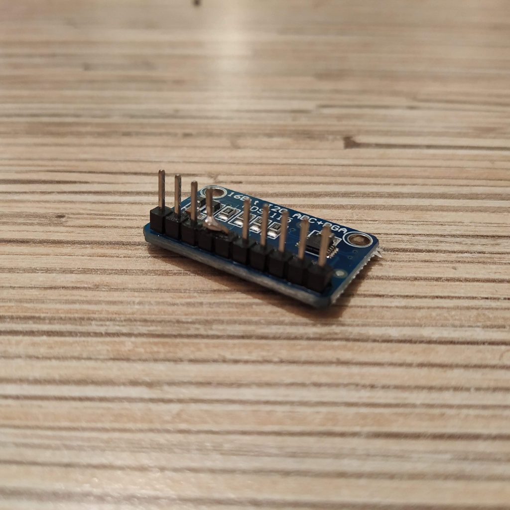
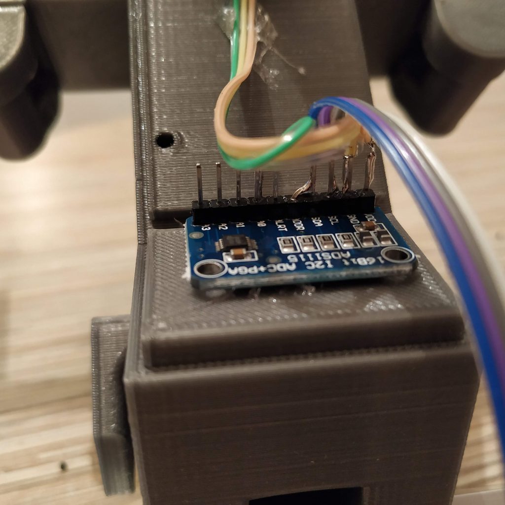
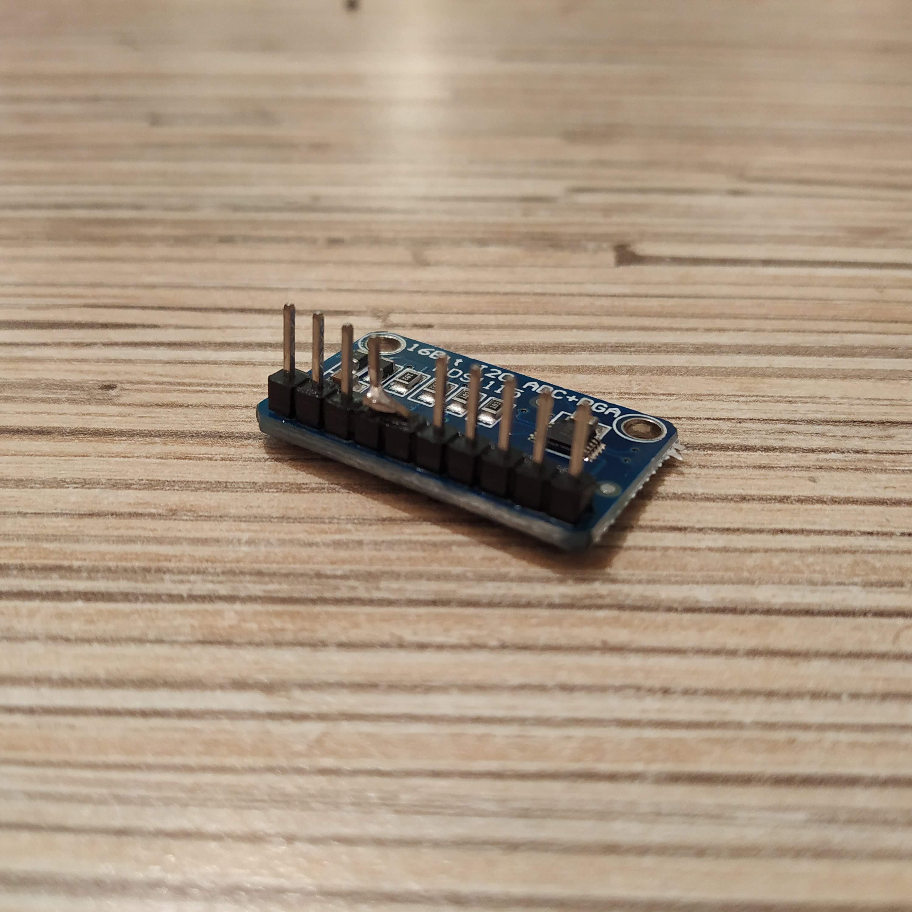
- Solder the header to an ADS1115 ADC board. Bend the ADDR pin, connect it to the SDA pin, cut an excess length of ADDR pin and solder it to the SDA pin.
- Solder 4-wire cable cut off the ribbon to 1st 4 pins of an Ethernet socket.
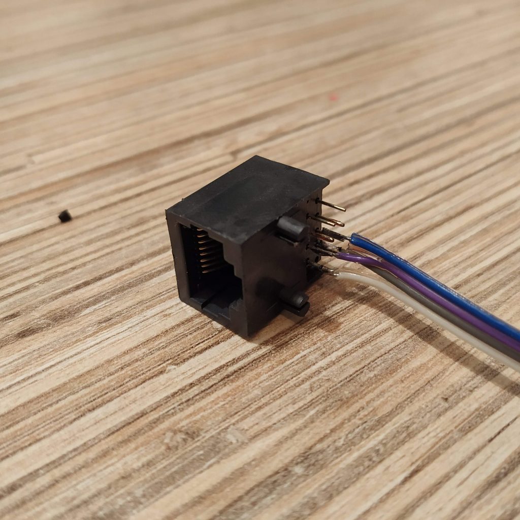
- Connect everything as follows:
VCC -> SS495A VCC -> ethernet socket pin 1 (orange-white wire on the plug)
GND -> SS495A GND -> ethernet socket pin 2 (orange wire on the plug)
ADDR -> SDA (bus address 0x4A)
A0 -> SS495A signal
SCL -> ethernet socket pin 3 (green-white wire on the plug)
SDA -> ethernet socket pin 4 (blue wire on the plug)
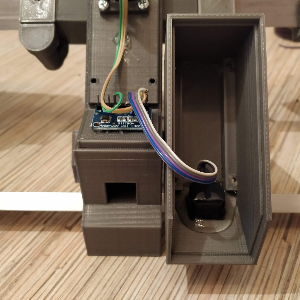
- Fix the ADC board to the frame with a drop of hot glue.
- Calibration time! Connect the pedals to the master controller. They will be assigned to the rudder axis of the 1st Arduino Leonardo in the list. Open the master controller sketch and uncomment the following line under “g_helicopter_pedals” tab:
//Serial.println(rudder); //uncomment to calibrate pedals
- Flash the controller, open Serial port monitor in Arduino IDE and carefully rotate the magnet holder until you will see the value close enough to 16384. Using the magnet holder adjustment screw, set desired travel of pedals. The further from the sensor is the magnet, the larger turn will be needed to reach axis boundaries. Default setting: adjustment screw barely touches the magnet (maximum travel). When finished, comment out “Serial.print” line again and re-flash the controller. That’s it calibration is now finished!
- The only thing that’s left now is to press-fit the Ethernet socket to the square slot of the electronics housing part, pour some hot glue to fix it there, install the housing part onto the frame and fix with 4 M3x50mm screws.
Congratulations! You’ve just built yourself a new set of pedals!


You can now pull an ethernet cable through a square cable channel in the frame, connect it to master controller and fly!
Is there also a mod for 5x5x5 magnets?
Have just added it for you =)
https://github.com/hc625ma/simchair_models/blob/master/Mods/Peripherals/Helicopter%20pedals/STL/pedals_magnet_holder_5x5x5mm_pedals12a.STL
Thank you very much ! Iam flattened by your service .
Regards Christian
You’re welcome!
Theoretically, 5x5x5mm magnet can give even larger possible pedals travel range. Let me know how it worked for you!
[edited to protect your email from spam]
Hey alex its only the instructions on how to put the pedals together
where is the rest of the gear (how to mount the cyclic and collective pieces together?)
you know how dumb i am
tony
Everything is under corresponding pages in the menu:
The gimbal: http://hc625ma.org/flight-stick-gimbal-608zz-reinforced/
Pneumatic mod: http://hc625ma.org/collective-pneumatic-mod/
everything else should be pre-assembled =)
Answered to your skype
For anyone having issues finding the aluminum in the USA here’s a link. Hoping to finish everything up soon. https://www.onlinemetals.com/merchant.cfm?pid=22324&step=4&showunits=inches&id=1634&top_cat=60
Thank you!
I will be posting an update for the rocker part in a couple of days. The new one will have a single aluminum pipe going through it, and I will also add a tool to drill it at an angle. Such design should suit better for a spring-loaded version!
Will post that link somewhere in a visible place.
Cheers!
Hello,
I noticed that 20×10 profile holes in pedal holders (mounts) have different depth. Left is 25 mm and right is 30 mm. Is it intentional or should I modify one of them?
Hi! Wow, that’s definitely an error. Thank you for noticing it, please re-download the repo – adjusted the cut in the left pedal to be 30mm deep as well! =)
Hey there,
i finished building the pedals and checked the whole wiring. When it comes to flashing the arduino leonardo i get the following error message:
simchair_i2c-master\master_controller\b_main.ino:50:48: warning: overflow in implicit constant conversion [-Woverflow]
int ADC_RANGE = 0.5 + pow(2, ADS1115_RESOLUTION);
Uploading finishes but the serial monitor doesn’t show anything.
Thanks for your help in advance
Hi Felix! This is a warning (Though may be in fact an important bug!). The software still has some bugs in it, but works quite good =)
Have you uncommented the “Serial.print” lines under g_helicopter_pedals.ino?
//Serial.println(rudder); //uncomment to calibrate pedals
Also, have you changed the baud rate to 115200?
To fix this warning, change
int ADC_RANGE = 0.5 + pow(2, ADS1115_RESOLUTION);
int COLLECTIVE_ADC_RANGE = 0.5 + pow(2, 10);
under main.ino, to:
uint16_t ADC_RANGE = 0.5 + pow(2, ADS1115_RESOLUTION);
uint16_t COLLECTIVE_ADC_RANGE = 0.5 + pow(2, 10);
Cheers!
Thanks for you help. It now works! Though the range is very small. I adjusted as described in the manual but I get a maximum of roughly 25-50% of the travel in joy.cpl and DCS (with linear settings). After adjusting the curvage in DCS I get more but then the controls are very sensitive. Is there a way to maximase the travel? I read about the adjustment screw but that does not solve the problem for me.
Thanks in advance
Felix, what magnet do you use? Can you take a photo of how it is installed?
–UPD
Just tried the current version of the software with my copy of pedals and the changes I advised yesterday, it seems to work fine, so it’s probably something hardware related. Please tell me more about your magnet!
Hey again. Using a normal 5x5x5 magnet with the correct mod magnet holder. Will take a photo and post it.
Now I have the problem that I get an output as usual on the serial monitor but the joy.cpl does not show any movement at all…. One step in the wrong direction..
What’s the range in serial output?
Between 14000 and 20000 roughly
That’s way too short. Please look at this picture:
These are poles of the magnet. The sensor “feels” the place where blue turns into red. Try rotating the magnet!
UPD: edited the picture to show the correct sensor position
I managed to adjust the magnet holder and shorten the M8 screw. Checked the magnet is in the right position. Now I get an output of 21000 – 11000. The range is greater but still after commenting the serial print, I do not get any movement in joy.cpl… Any other ideas?
In setup_pedals() in g_helicopter_pedals.ino, change the following:
if (INVERT_RUDDER == 1)
{
simchair.setRudderRange(ADC_RANGE, 0);
}
else
{
simchair.setRudderRange(0, ADC_RANGE);
}
to:
if (INVERT_RUDDER == 1)
{
simchair.setRudderRange(21000, 11000);
}
else
{
simchair.setRudderRange(11000, 21000);
}
Does it change anything? The range is still fairly bad – around 1/3 of what it should be =( Can you please make a photo of the installed magnet? I guess I will have to order some of these 5×5 thingies for testing =)
Sorry for the late answer. I managed to grab some new SS495A and printed the magnet holder again. Also I didn’t use the screw which lead to lowering the range by roughly 70%. Now I have a range of 14000 to 32500. I adapted your last edition of the g_helicopter_pedals to those numbers. It does work now. Just need to fix the magnet holder to the M8 screw. It doesn’t really hold on to it very well. I’ll be solving it this week.
Now the only problem I have is that my certain range and your center position of 16384 don’t fit together. I need to apply right pedal to get a center position in DCS and joy.cpl.
How/ where do you change the center of the pedals?
Kind regards
Felix
Kind regards
Hmm, still not sure I understand the nature of your issue, but try this:
In setup_pedals() in g_helicopter_pedals.ino, change the following:
if (INVERT_RUDDER == 1)
{
simchair.setRudderRange(ADC_RANGE, 0);
}
else
{
simchair.setRudderRange(0, ADC_RANGE);
}
to:
if (INVERT_RUDDER == 1)
{
simchair.setRudderRange(21000, 11000);
}
else
{
simchair.setRudderRange(11000, 21000);
}
This should change the range for axes, then you can set the center mechanically.
Can you upload some photos? http://hc625ma.org/upload-a-file/
Is it possible to get live help via discord? I think that’s a better solution. Hardware works. I Think it now is a software issue.
Sure, lets do anydesk in a couple hours.
You still only have a half of what you should be getting!
https://discord.gg/3XuZMDY <- here's the discord =)
Thx for your job guys!!!
you’re welcome =)
Hi:
Reading the Helicopter pedal instructions and I think there is a numeric error in Step 3.
it reads: “3. Press fit the 30mm piece into the frame carefully”
Shouldn’t the instruction read: ” 3. Press fit the 300mm piece into the frame carefully”?
Dwight…………………………..
Hi Dwight! Thanks for pointing that out, fixed it =)
I am trying to Flash the Arduino board and I get this message:
“Arduino: 1.8.9 (Windows 7), Board: “Arduino Leonardo”
Sketch uses 23036 bytes (80%) of program storage space. Maximum is 28672 bytes.
Global variables use 1698 bytes (66%) of dynamic memory, leaving 862 bytes for local variables. Maximum is 2560 bytes.
avrdude: butterfly_recv(): programmer is not responding
avrdude: butterfly_recv(): programmer is not responding
avrdude: butterfly_recv(): programmer is not responding
avrdude: butterfly_recv(): programmer is not responding
avrdude: butterfly_recv(): programmer is not responding
Found programmer: Id = “�”; type = �
Software Version = (.”
It is color coded RED and I assume that it is a problem but I have no Idea how to solve or where to look.
When Plugging in the PL2303 device do I remove the (+/-) plugs already in the Arduino board and replace with PL23023 (+/-) leads?)
Finally got this resolved with an immense amount of help from Alex.
1. The Ethernet Jacks I had were “magnetic and some of the pins we use in the project were pre connected. That ain’t good. I got 16.pcs of plain jain Ethernet Jacks where all pins are isolated from each other.
2. The Aurdino Leonard board plugs into your PC with a standard USB port. I was trying to use the PL2303 with the Arduino Leonardo board as shown in the instructions (as I interpreted them).
3. Changing to the new Ethernet Jacks had a rear exit not a top exit and I wired them reversed mirror image. I did 1x port at a time to verify it worked and then did all of them.
4. The magnet holder was tilted slightly and hitting the SS495a and restricting output range.
Now, with all that said, I have serial output on the Pedals. Off to the next peripheral. 🙂
Hey 🙂
Is it possible to use just the peddals with a leonardo?
Somehow i couldn’t find the file with the code
thanks 🙂
Hi! Sure, you can use any of Simchair devices separately. You can’t find the file with code, because there simply isn’t one (just like with the cyclic), as pedals use an i2c ADS1115 ADC =) All of their code is in the master sketch. Just uncomment the pedals in the device definitions tab and you’re good to go =)