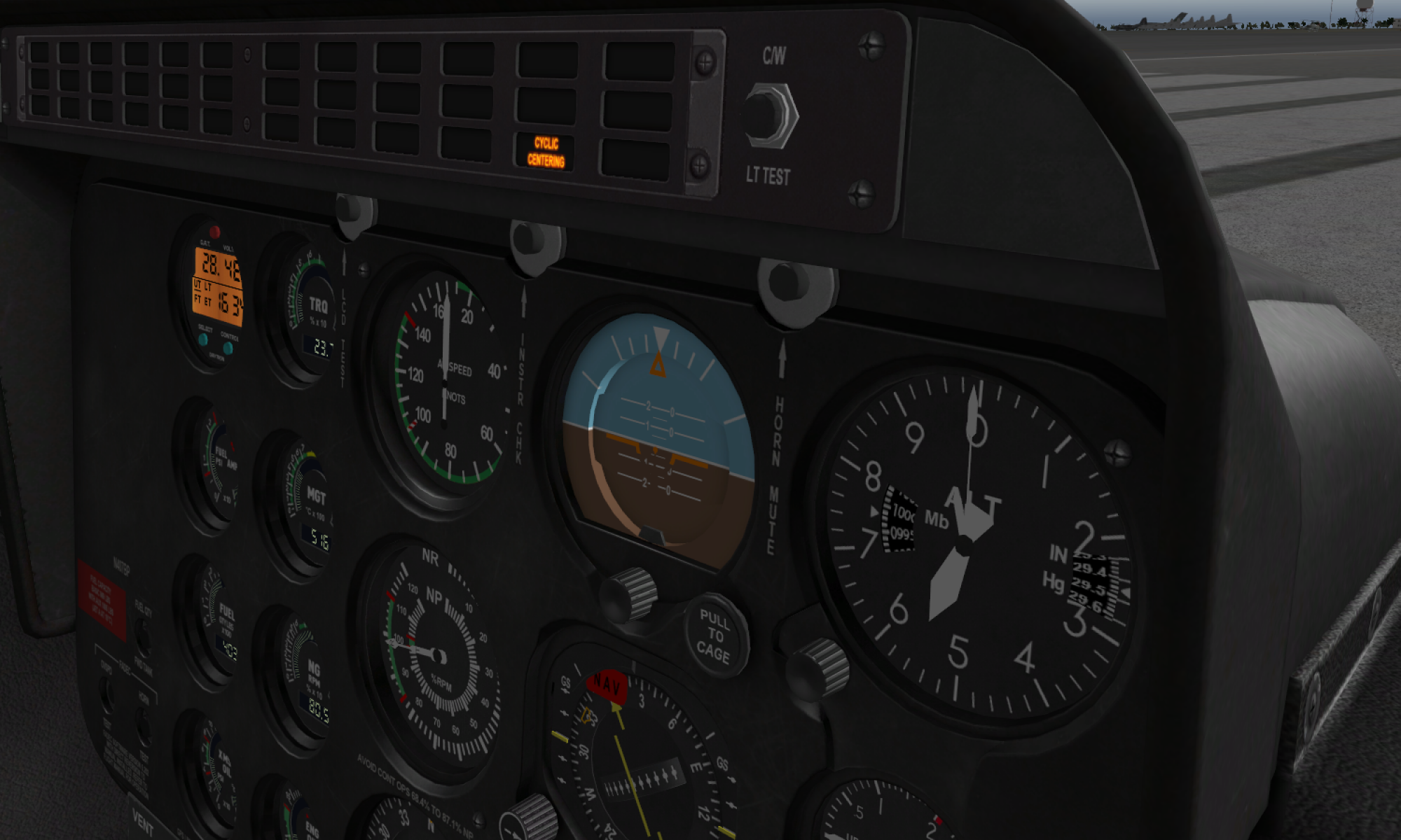
Summary
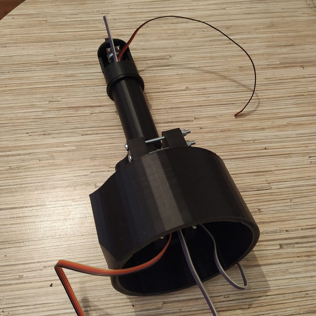
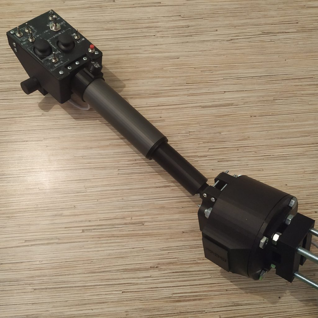
This is a single-throttle Bell-style collective lever. It has a 200-degree throttle travel range and a 40mm diameter, just like the real one. It is specially designed for use with switchpanels (heads).
Components
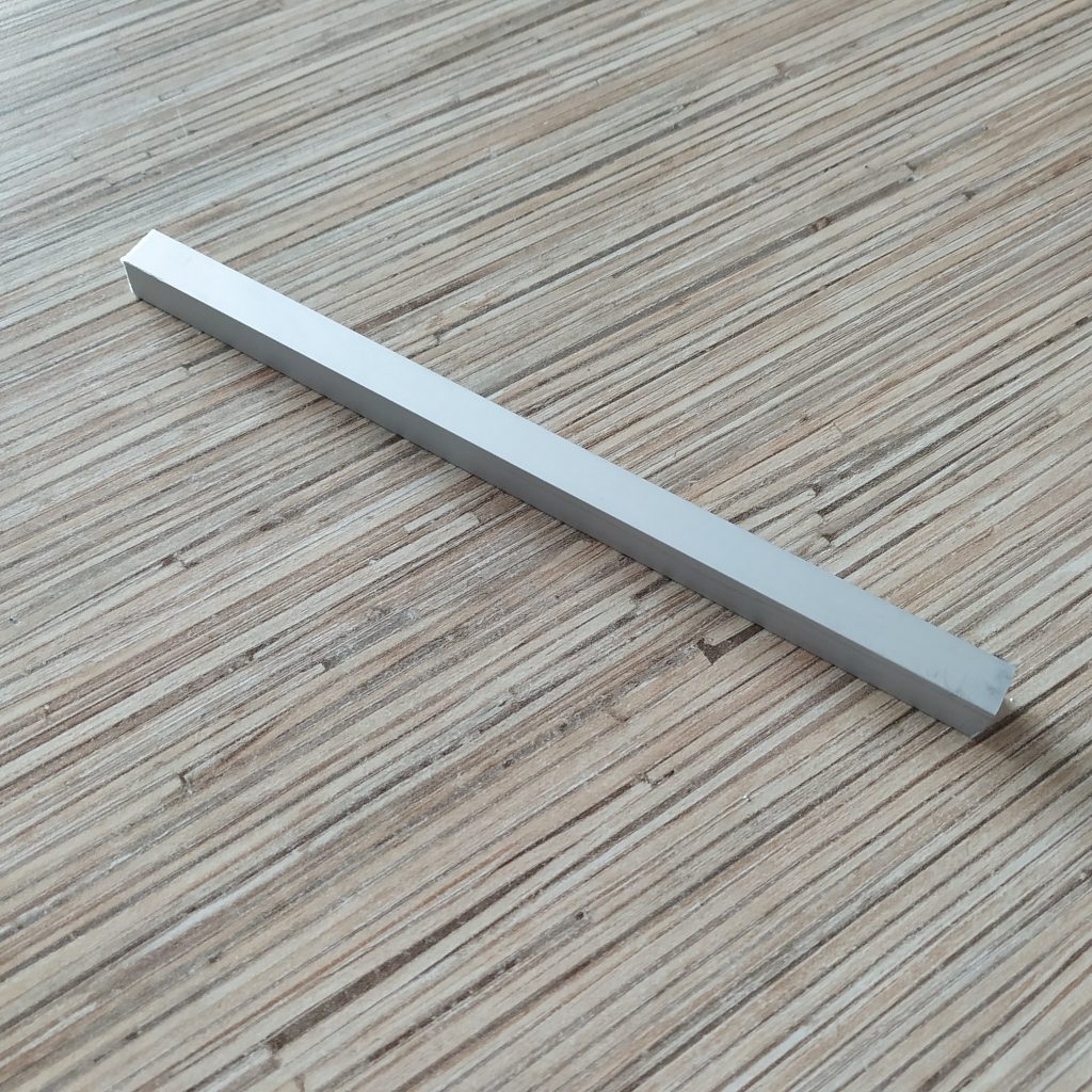
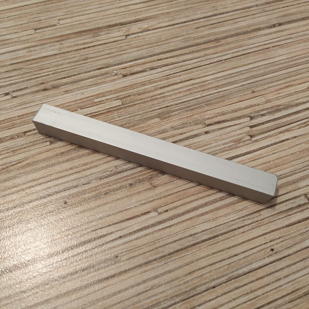
1 x 10x10mm aluminum square pipe
1 x 20×10 aluminum rectangular pipe for chair mounting (the mount for the IKEA GUNDE chair is included)
1 x SS495A hall sensor
1 x 10KOhm LINEAR potentiometer
(https://goo.gl/vbi1Zh)
1 x 6x6x4mm square magnet
4 x 3x40mm screws and nyloc nuts to connect the frame to its enclosure
2 x 3x20mm screw for lever connector axis strengthening
4 x 3x45mm screws for tensioner halves contraction
2 x M4x110mm screws and nuts
4 x m8x75 bolts, spring washers, and nuts
2 x 608 bearings (standard skateboard bearings)
1 x Arduino Pro mini
1 x Simchair MKIII I2C controller
super glue (cyanoacrylate)
Available mods
- 5x5x5mm magnet holders
- pneumatic mod
- physical throttle latch mod
Special features
- aircraft compatibility modes support
- collective hold support
Downloads
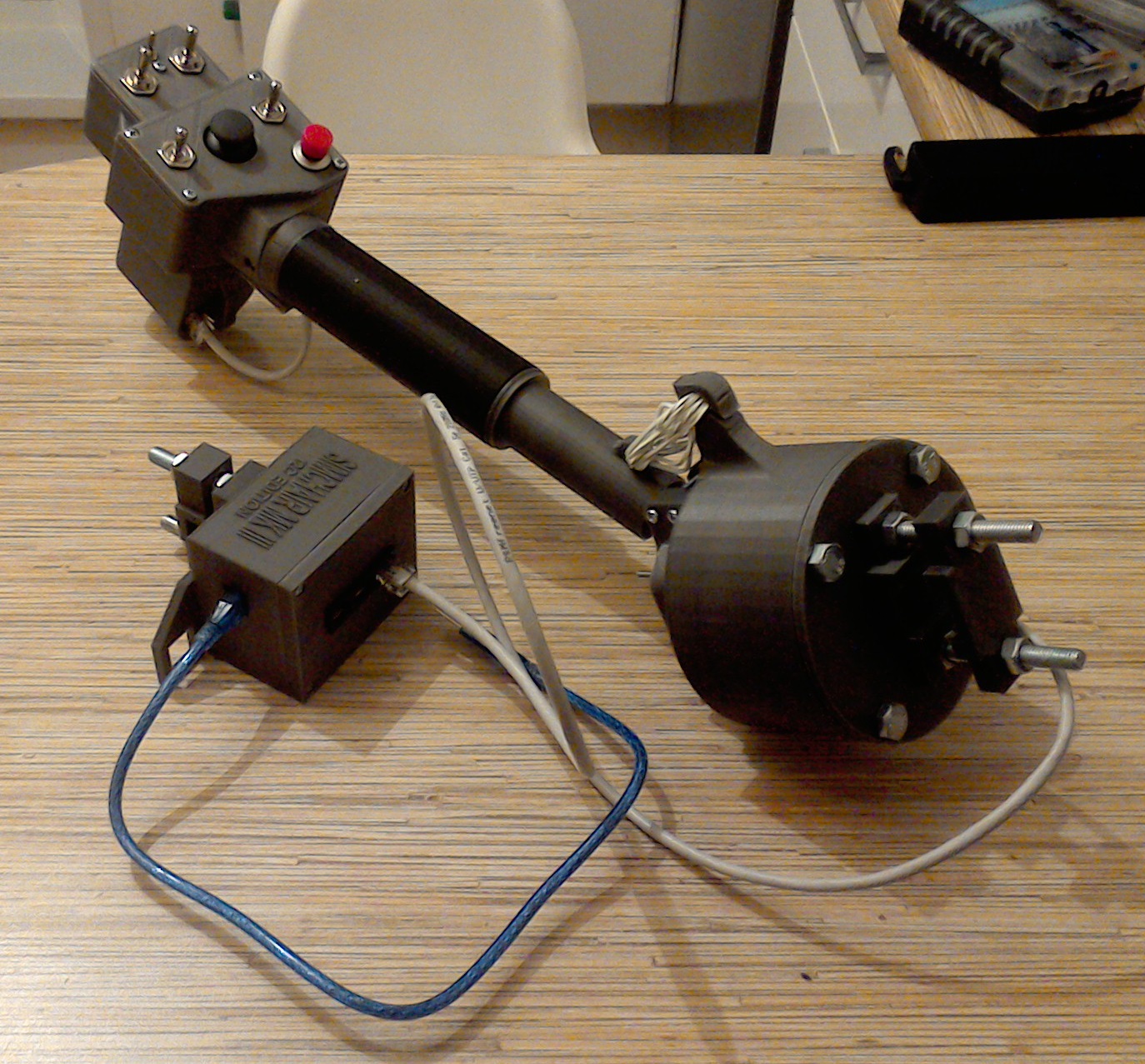
Assembly
Assembly is very similar to a twin collective and pretty straightforward. Will add the manual soon, meanwhile, if you have any questions, please contact me through comments.
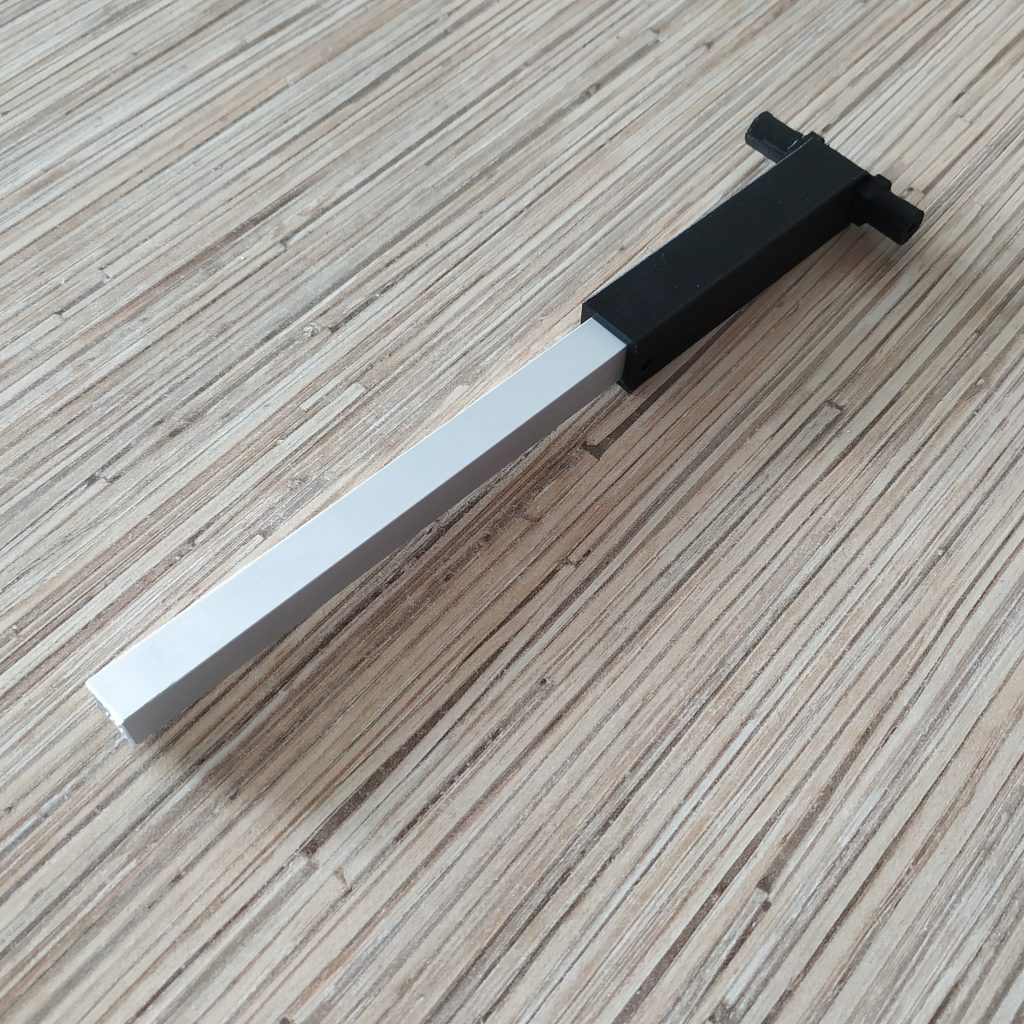
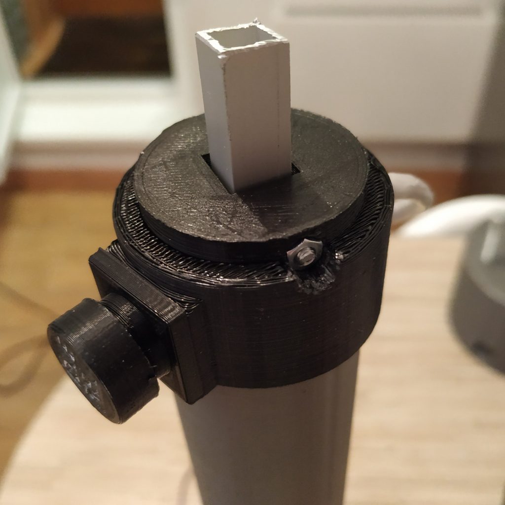
1. Cut a 180mm piece off a 10 square aluminum tubing. File edges of the cut.
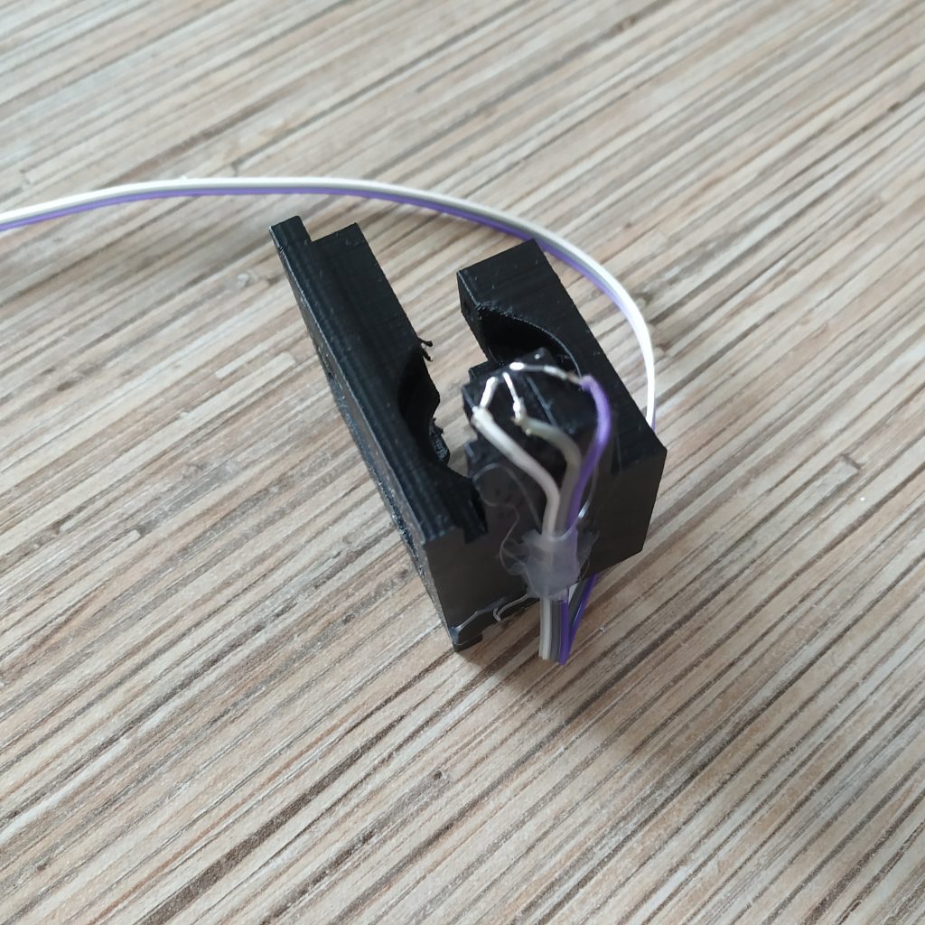
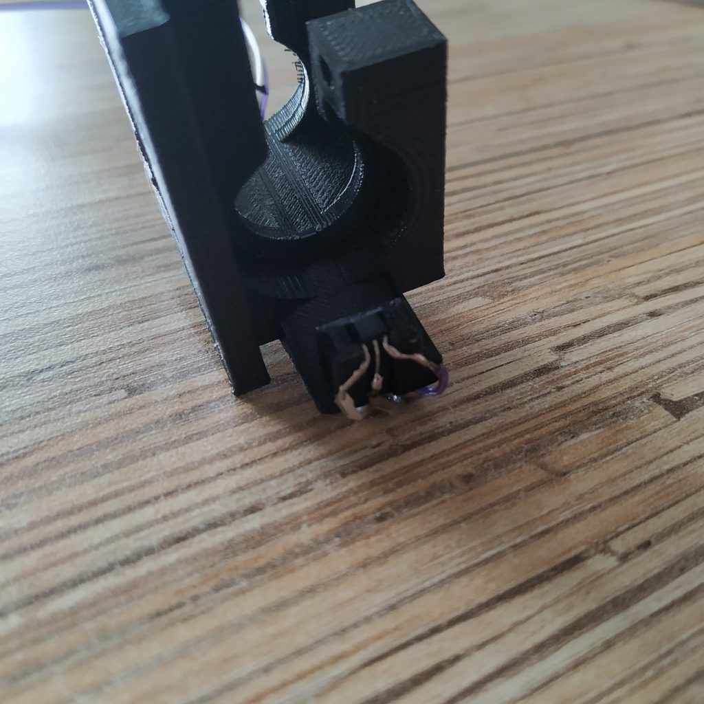
2. Press fit an SS495A sensor to the socket and solder a 3- wire cable to it. Attach the cable to the underside of the lever frame part with hot glue.
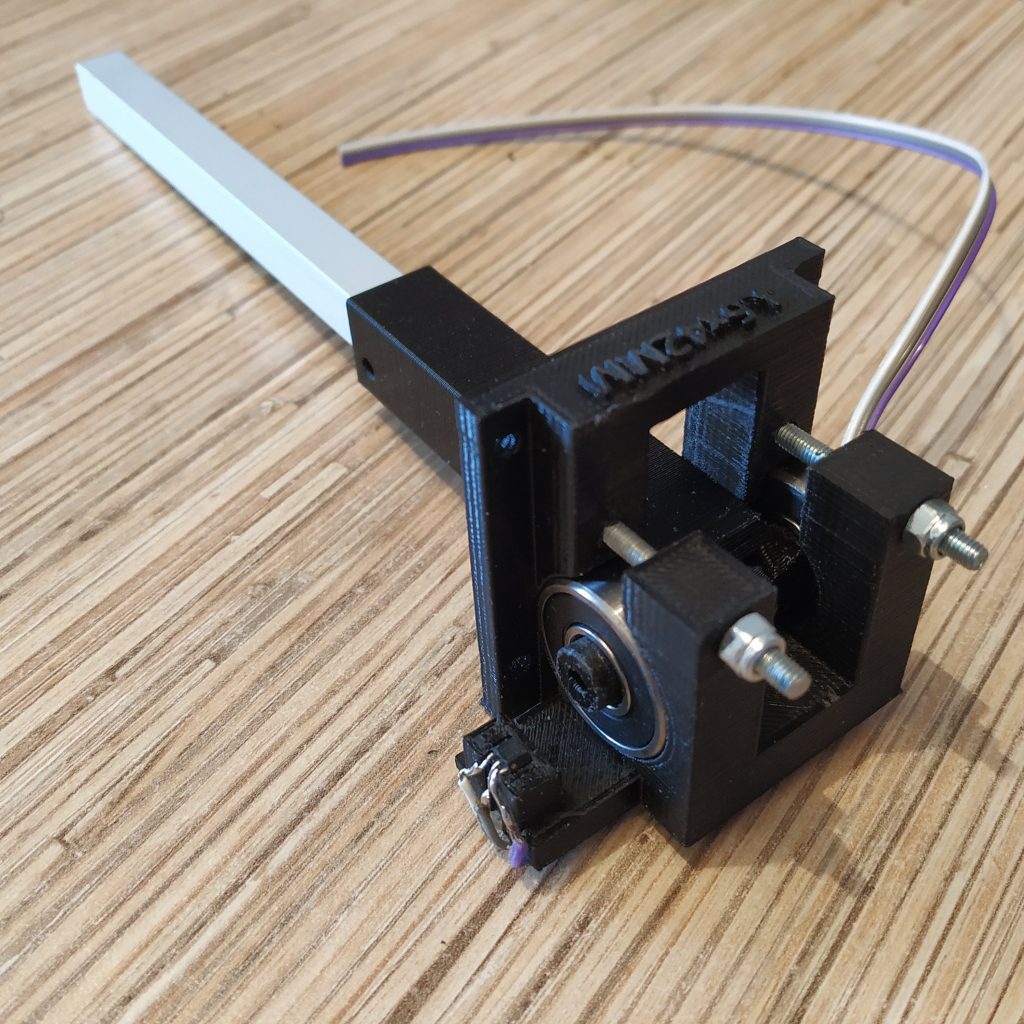
3. Insert the alu piece into the lever connector part.
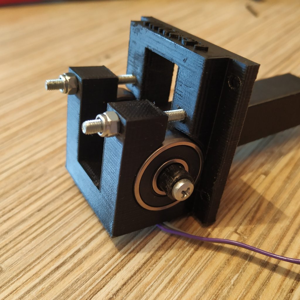
4. Insert lever connector part into the frame, put bearings on. Insert 2 M3x35mm screws, put nyloc nuts on them.
5. Secure the sensor in its socket with a drop of cyanoacrilate glue (superglue).
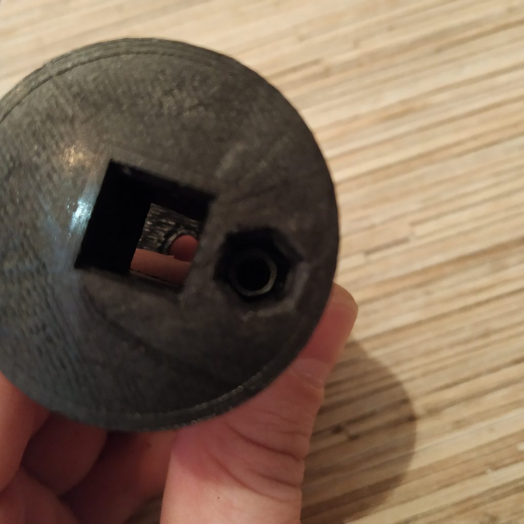
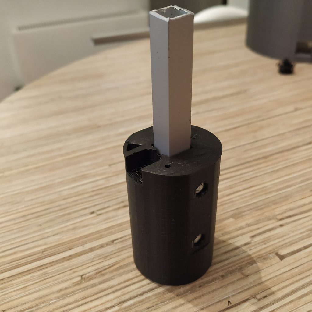
6. Screw an M3x40mm scre into the frame connector to remove supports from the hole.
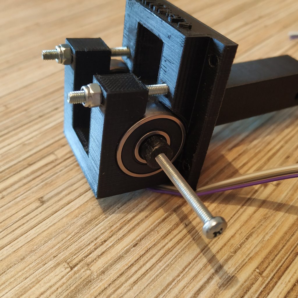
7. Insert an M3x20 screw into the lever connector part from its right side.
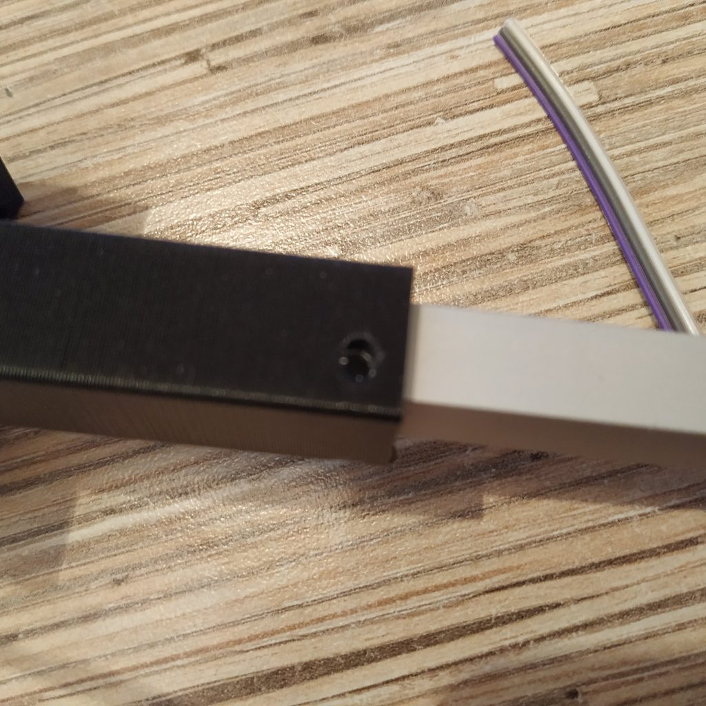
8.Drill a hole in the 10mm square pipe piece through the hole in the lever connector part.
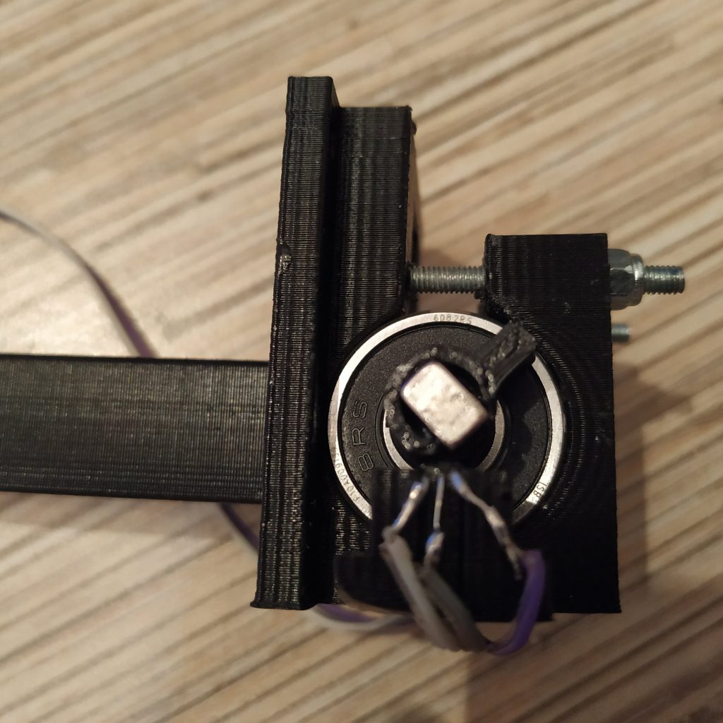
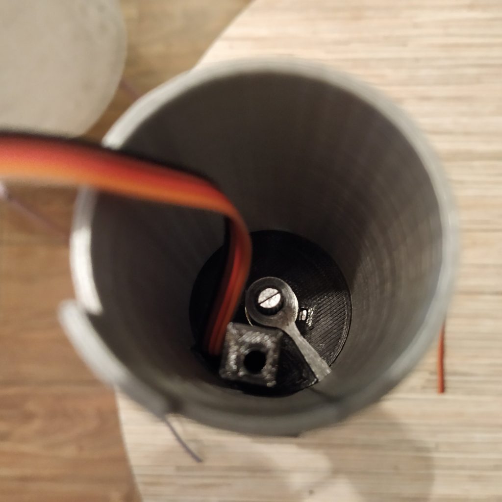
9. Attach the magnet holder, fix it with an M3x20mm screw. Insert the magnet into its socket in the holder and secure it with a drop of super glue. Turn the magnet holder as shown on the next picture:
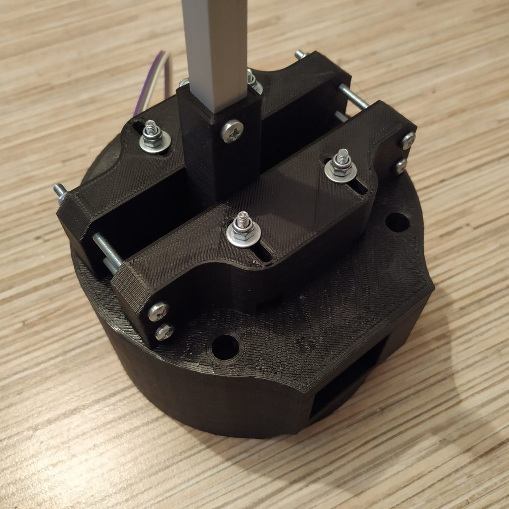
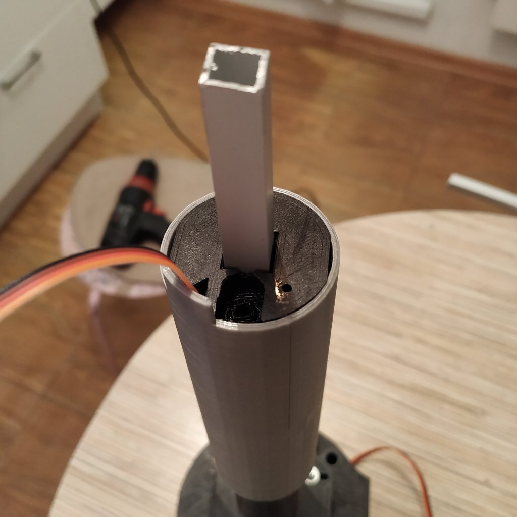
10. Insert the lever frame assembly into the housing. Fix it with 4 M3x40mm bolts. We will use the latest mod with a side window.
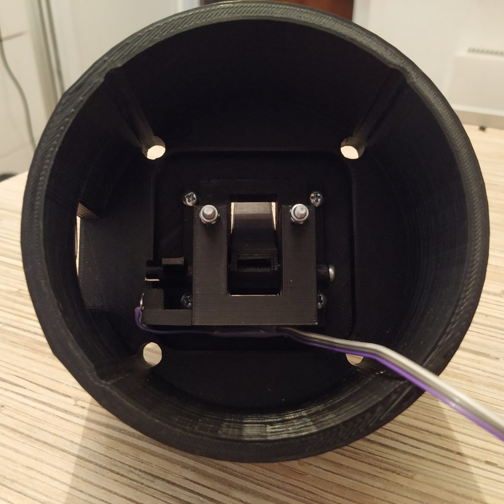
11. Put 4 nuts with washers onto the bolts.
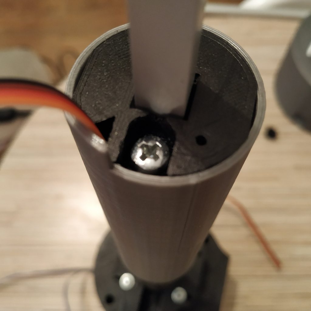
12. Fix the 10mm pipe in the lever connector part with an M3x20mm screw. Screw head should be on the window (left) side.
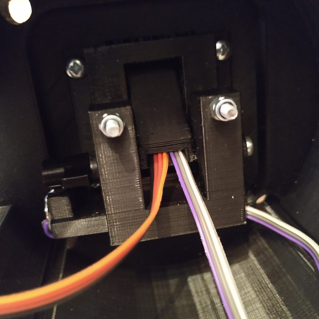
13. Put tensioner halves on. Widen holes in one of the parts with a PH0 type screwdriver and install that part on the left side of the lever (the one with the window). After that, put another part on and add 4 washers and nyloc nuts. Tighten them in a way so tensioner halves will be free to move sideways, but not forward.
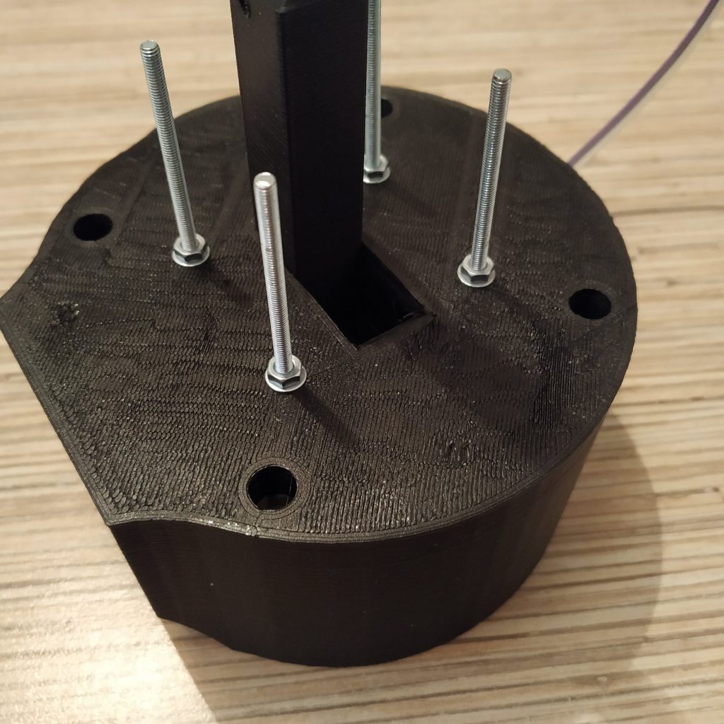
14. Install 4 M3x50mm screws from the left side, put nuts on their other ends. Assembly of the base is finished! Let’s move on to the lever part.
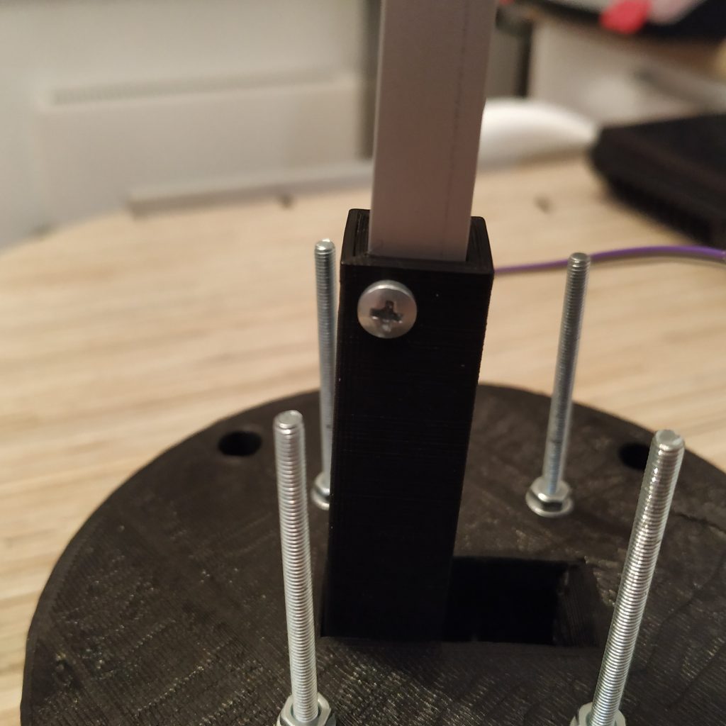
15. Install the decorative cover onto the 10mm tubing.
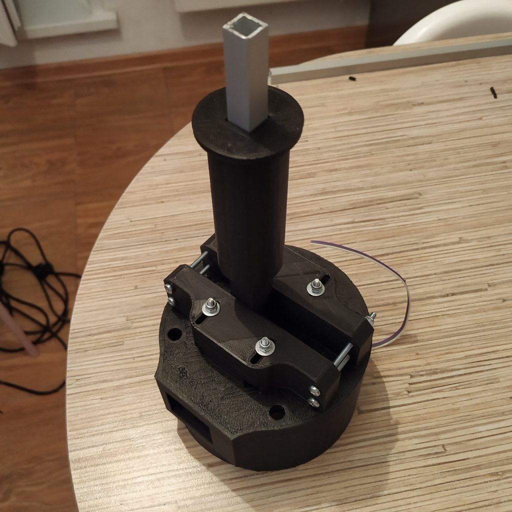
16. Press-fit an M4 nut into the socket in the throttle frame part 1.
17. Insert a potentiometer into throttle frame p1.
18. Put the throttle frame part 1 onto the 10mm tubing. Drill holes in 10mm tubing through holes of the frame part 1.
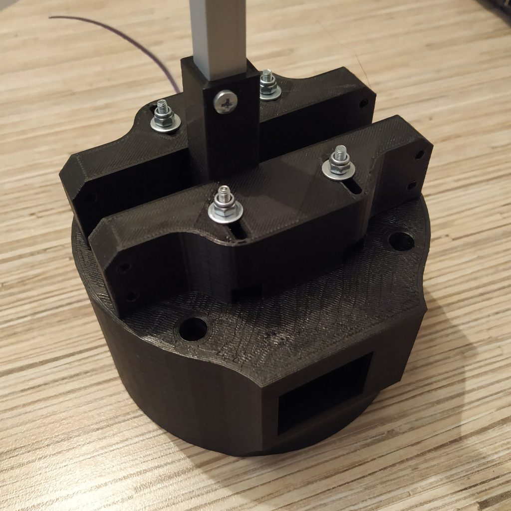
19. Press-fit nuts into their sockets and insert 2 M3x30mm screws.
20. Route 4-wire I2C cable and 3-wire pot cable through the lever. This step may require some patience depending on wires used.
21. Solder the pot wires and route I2C cables through the cable channel in throttle frame part 1.

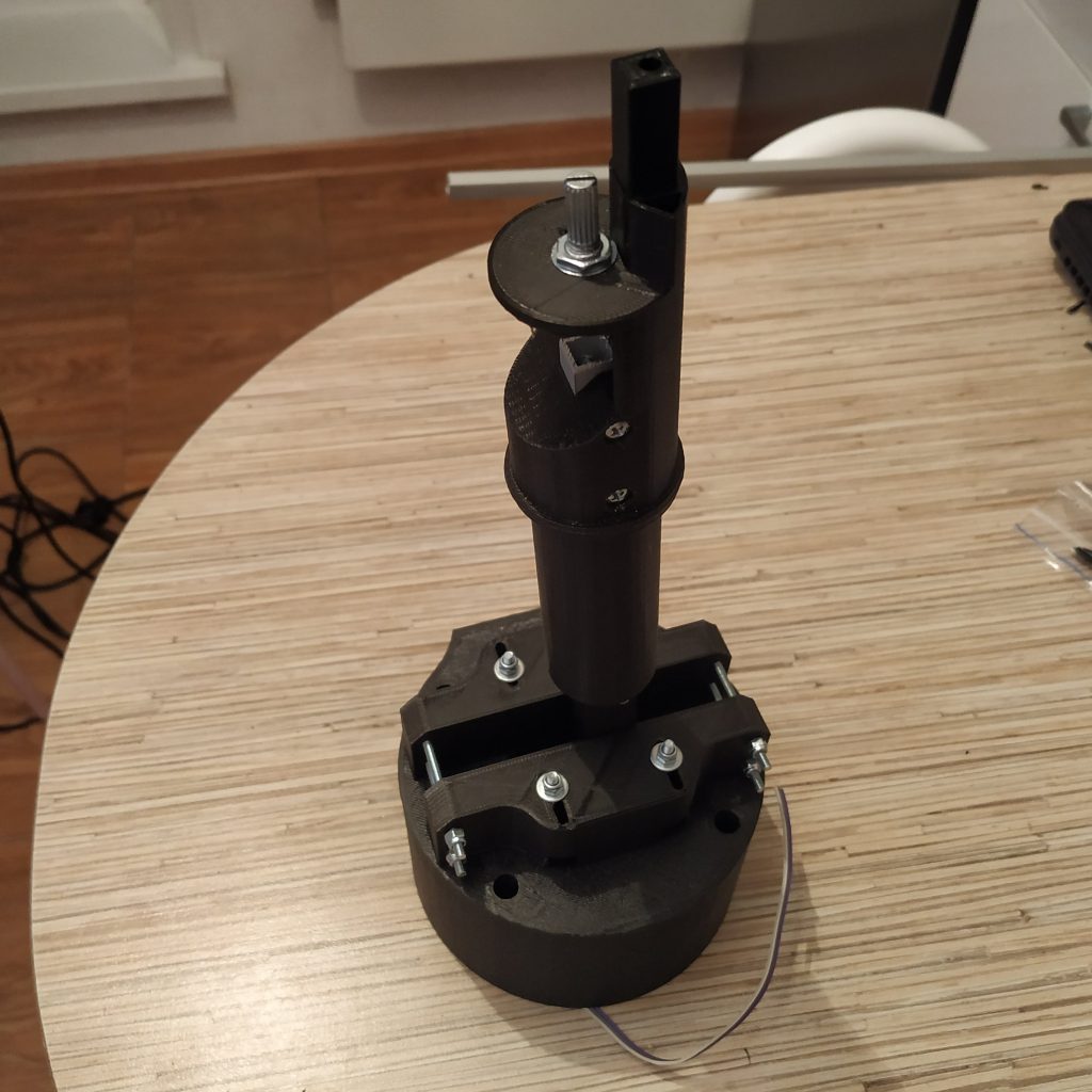
22. Turn the pot fully to the left, then just a notch to the right. Put the throttle grip on (widen its hole or squeeze the pot knob with pliers if needed) in a way that it will be in “full open” position (see picture below). Make sure it rotates freely.
23. Cut a 105mm piece of alu tubing and file its ends.
Insert the tubing piece into the throttle frame p2, drill it through its holes, press-fit nuts to sockets of throttle frame p2 and use 2 M3x30mm screws to fix the tubing piece in it.
24. Route 4-wire I2C cable through the throttle frame p2 part. Insert the part into the throttle grip, so the pin of throttle frame p1 will go into the socket in throttle pin p2.
25. Fasten 2 parts of the throttle frame together with an M4x110mm screw.
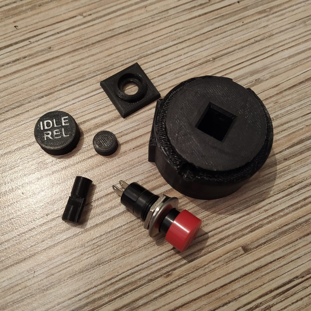
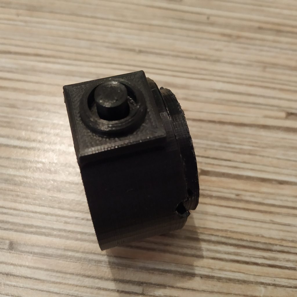
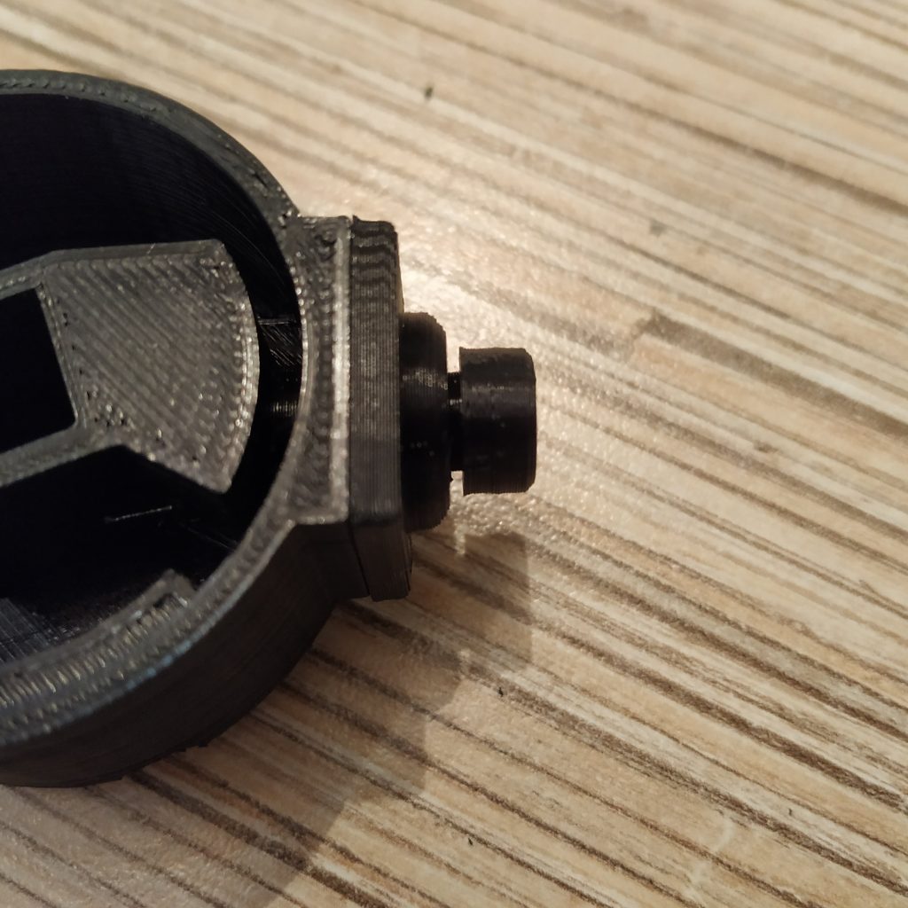
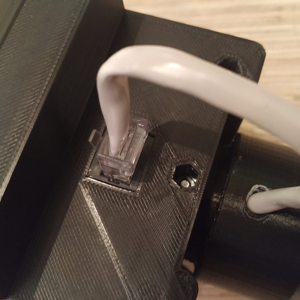
26. We will be using the physical throttle latch mod for this build. To assemble the modified I2C cable housing part, we will need a PBS-16B button, as well as printed parts from the mod folder. Note that the latch pin should be printed with 100% infill.
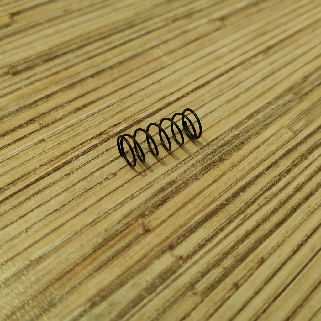
27. Disassemble the button and take out the spring. Put it into the throttle latch socket.
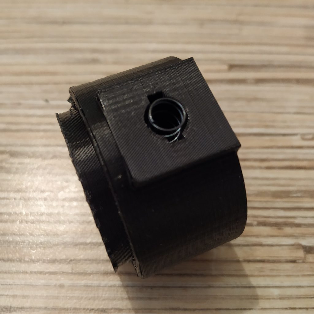
28. Insert throttle latch pin into the socket, squeezing the spring.
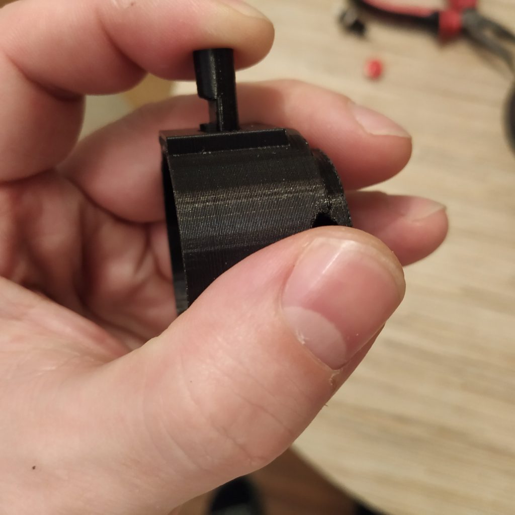
29. Glue the socket cover to the I2C connector housing part.
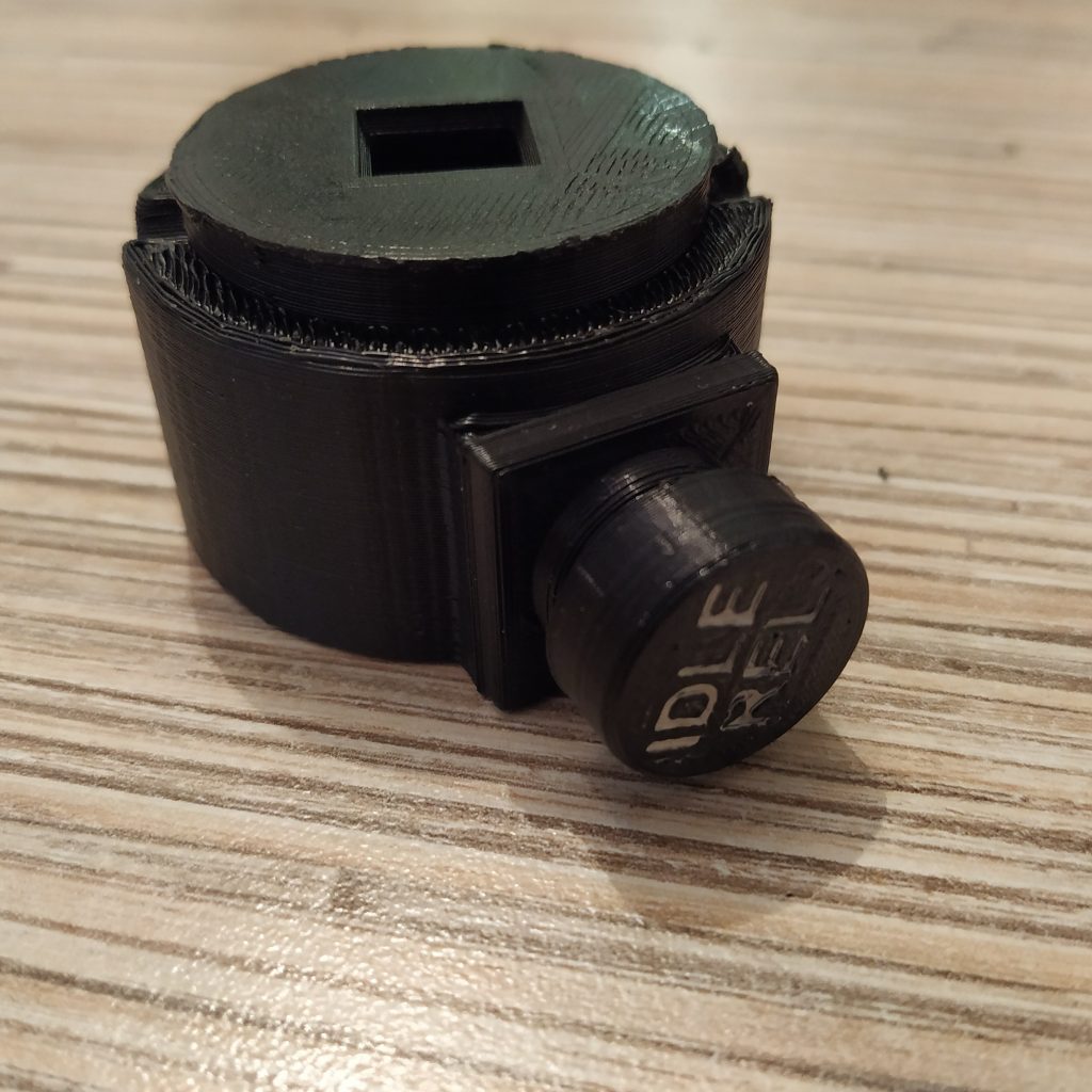
30. Glue the button top to the latch. You can choose between a small button and a scale 206-style one.
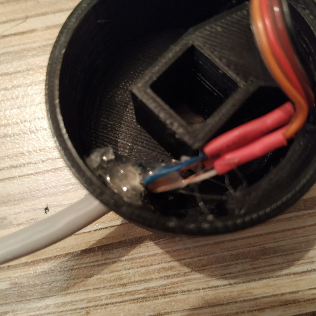
31. Solder the 4-wire I2C cable to an ethernet cable.
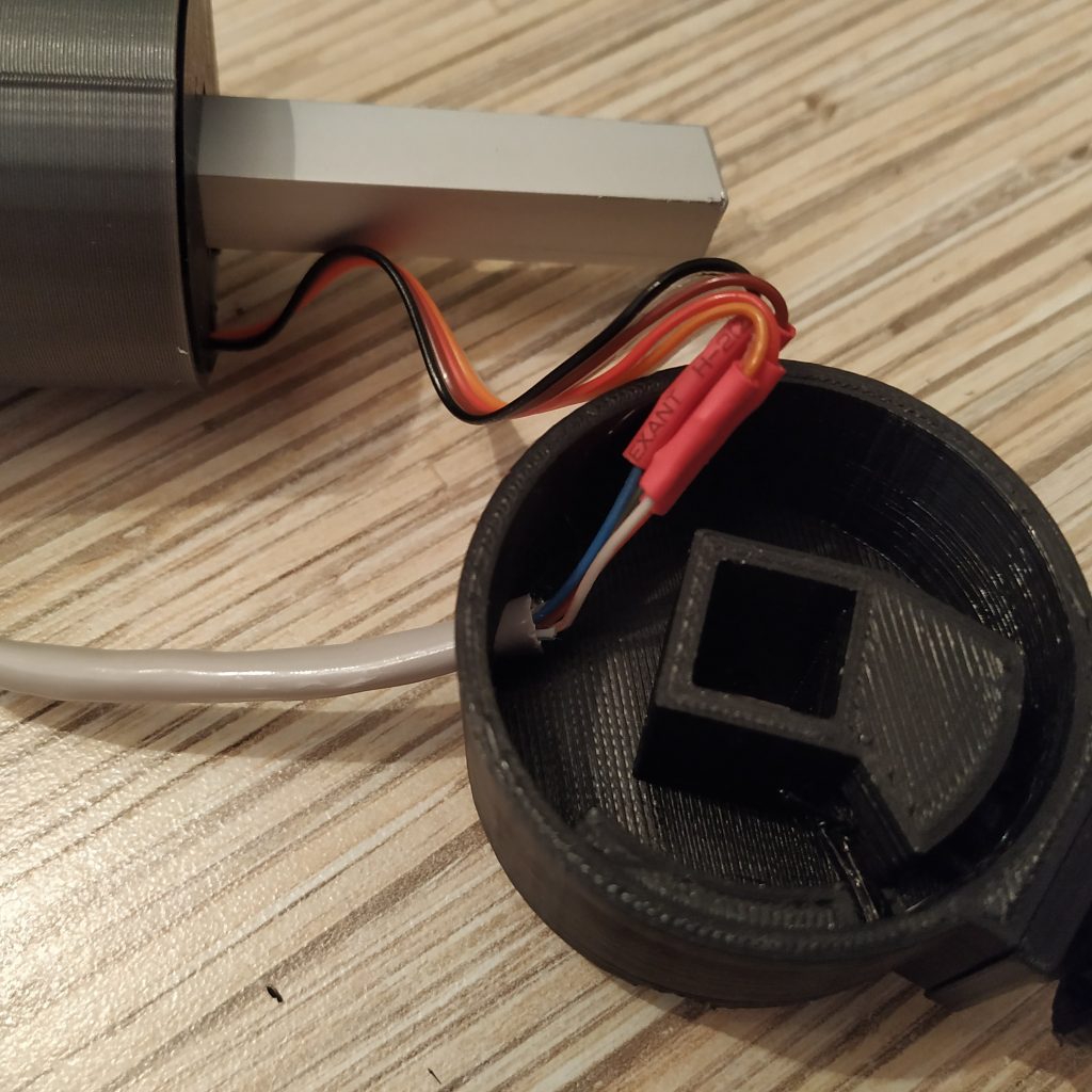
32. Add some hot glue to fix the ethernet cable in place.
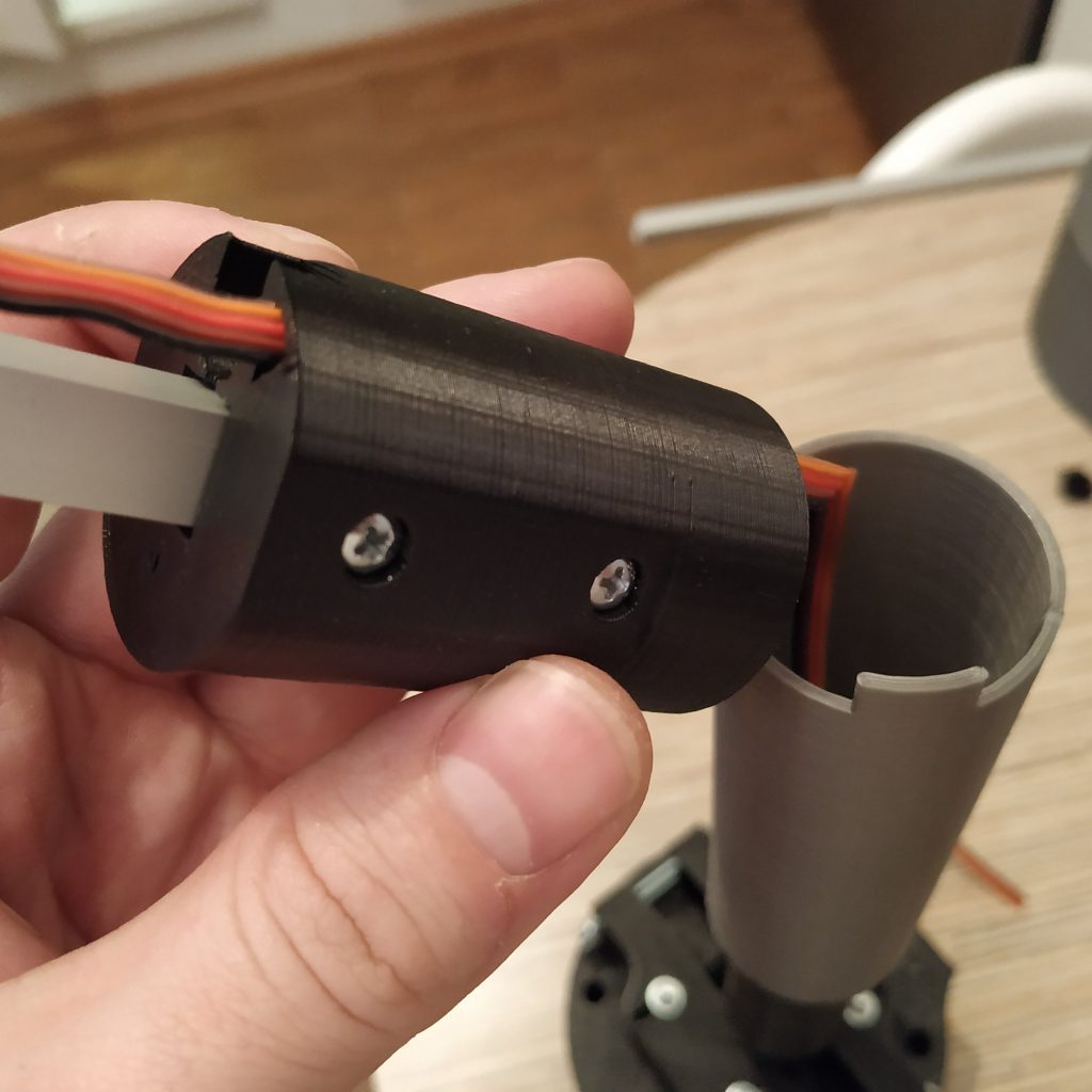
33. Put the I2C cable housing onto the lever. Secure with an M3x35mm screw.
34. Solder cables to an Arduino Pro Mini board as follows:
- ALL +5V (including Ethernet socket pin 1 – white-orange wire) -> Pro Mini VCC
- ALL GND (including Ethernet socket pin 2 – orange wire) -> Pro Mini GND
- Ethernet socket pin 3 (SCL) -> Pro Mini pin A5
- Ethernet socket pin 4 (SDA) -> Pro Mini pin A4
- SS495A1 signal -> A0
- THROTTLE POT signal -> A1
35. Flash the board with single_collective.ino and calibrate the lever.
36. Now it’s a good idea to do some cable management.
37. Put the lid onto the housing and secure with 4 M8x75mm screws.
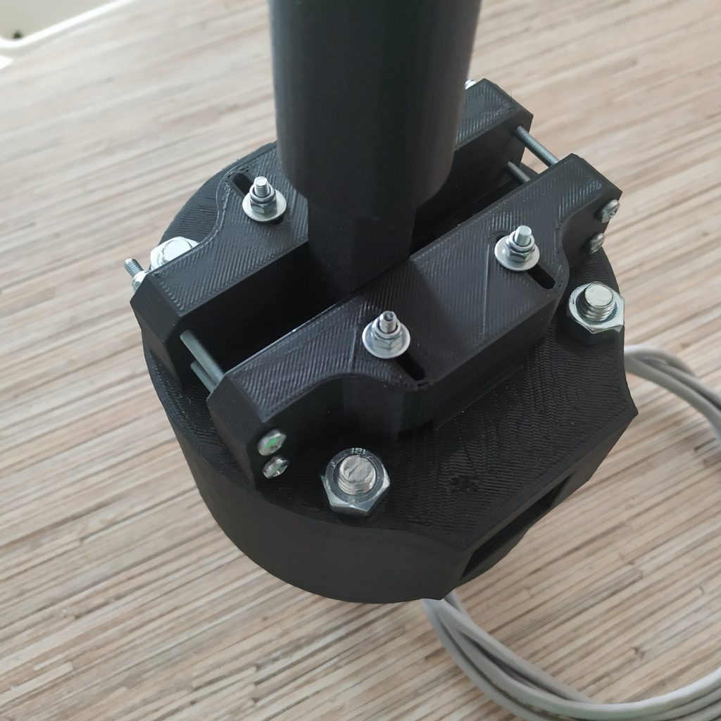
38. Make sure cables are fine inside of the enclosure and nothing touches the magnet, then close the hatch.
39. Install a head and drill holes in the square tubing where a mounting screw goes, then insert one.
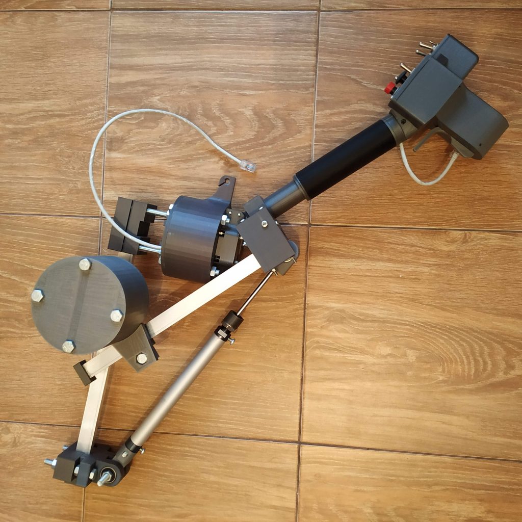
Congratulations, the lever is finished! Install the pneumatic mod and enjoy realistic helicopter flying experience!
There’s also a very detailed build log by Peter, be sure to check it out!
Peter
September 13, 2018 at 23:13 Edit
I also watched your build video but while it is helpful in some parts, many things remain unanswered. OK, I found out that I can not comment on the respective pages, so here goes. I will ask questions as my build progresses, and I will quote the relevant passages from the “simple collective” and the “twin collective assembly manual”:
1) “Start with press-fitting an SS495A sensor into its socket.” – The sensor has a broad side and a narrow side. The sensor is placed horizontally, with the broad side facing downwards. Is that correct?
2) “Solder its wires and bend the legs, fix everything with drops of super glue.” – How long should the wires be – 10-15 cm?
3) According to this datasheet ( https://goo.gl/Vqv5MM ), when the broad side is facing downwards then the wires from RIGHT to LEFT should be: ground, -, +. Is that correct?
4) “Then, insert the lever connector into its frame and press-fit 608zz bearings. Insert M3 screws and put nuts onto it to fix bearings in place.” – So on the video you use ONLY ONE M3x45 screw which you put through both bearings, but no nuts? Then you use 2 M3x40 screws to strengthen the construction, but again no nuts?
5) “Put the magnet into its socket.” – Which socket? Is this the “magnet holder” part? But where does the magnet holder go? It is never mentioned, and on the video it suddenly is on the side of the SS495A… The magnet holder is also an exccentric part, and I need to know how to orient it.
Sorry for the stupid questions but this is as far as I got…. ¯\_(ツ)_/¯
Thanks for your help so far! I am looking forward to continue.
Reply
hc625ma
September 14, 2018 at 06:36 Edit
Great questions! I will add page comments today)
1) Yup, narrow side towards the magnet (flat side downwards)
2) for ss495a, yes. Other wires should be longer as they’ll go through the lever. A good idea is to put printed parts on the table to get a rough estimate of needed wire lenghts.
3) When the broad side is facing down, legs are towards us, from right to left: signal, GND, VCC(5v), or vcc,gnd,signal from left to right)
4) It will be easier to see with parts at hand. You will need 2 screws to fix bearings in their sockets (do not overtighten!), and 2 short (20mm) screws to insert into the lever connector from both sides
5) magnet holder goes to the side of the lever connector, where an ss495a socket is on the frame. You fix it (do not overtighten) with one of strenghtening screws you insert to the lever connector. The idea is, it can rotate for mechanical calibration of the lever. You adjust screw until you can rotate it with a slight force, so it wont rotate on its own. Then you insert a magnet, it should hold itself against the screw head. Orientation of the magnet holder: cut side towads the sensor, holder handle towards enclosure bottom lid (you turn it by holding this handle with pliers during calibration), choose default rotation angle so that when the lever is roughly in the middle of its travel, the magnet is above the middle of a sensor.
Thank you for copying my comments and enabling posting on this page!
With your helpful suggestions, I managed to make some progress. Here is a little gallery of how far I got: https://imgur.com/a/fjzrTKn
As you can see, i had to modify the socket for the sensor little bit, because my SS495a is a little too big. I would also suggest making the “slot” on the side (where the legs of the chip go) a little more trapezoid for easier routing.
Also I would suggest increasing the size of the hole for the horizontal M3 screws (which fix the bearings in the gimbal) because I had to file the holes until the screw-heads were able to penetrate enough to be flush with the surface.
I will try to continue withe the build and post more comments and questions as I got long. Thanks for everything!
Everything looks good! A little warped though. What are the print settings your friend uses? Looks like either it’s not PLA or not enough layer cooling. If printed in other plastic or without proper cooling, parts will shrink and all holes, sockets etc will be smaller than they should. This is bad, because building the rest of the lever (where you need to put stuff onto the aluminum pipe) may become a pain =) You can try using a plastic part printed with the same settings instead of an alu pipe in this case. Still, I don’t recommend printing it in ABS, as all the tolerances and clearances are chosen with PLA in mind.
You are right about the warped part! I will continue on and see if it is worth the effort of retooling and sanding each part…
However I have some more questions:
1) I am confused on how long should the aluminium pipe which goes into the “single collective lever” part be? On the video at around 15:00 you show the pipe, but the length it not mentioned. On the “simple collective” page the length is given as 25cm. And when I imported your models (.sldasm and sldprt) into Autodesk online viewer, the length of the pipe came out as around 17cm.
2) Speaking of alu pipes: I guess that I will need more pipe to connect the head with the parts “single collective thottle frame p2” and “single_collective_head_i2c_connector_housing”. How long should that one be?
3) About cable routing: If I understand your explanations in the video correctely, I will have to deal with the routing of 2 cables: 1x from the potentiometer inside the ” single_collective_throttle_frame_p1″-part and 1x with the ethernet cable coming from the bottom of the AB412 head part. My question is: How do I route the ethernet cable invisibly through the alu pipes? I can’t see a proper way.
By the way: Uploading the .sldasm files was a great help in figuring this out in 3 dimensions!!! Thanks again for your help! I love this project!
You’re welcome! =) You’re right, you have 1 3-wire potentiometer cable, and one 4-wire I2C cable (which is soldered to the ethernet cable and i2c pins of an Arduino board), which is cut of the same rainbow ribbon cable. One super important notice: do not touch screws (that are below throttle frame part 1) after wires are routed through the lever, you will cut them =)
About the length of the pipe: just put printed pieces next to each other (to see how they will look when assembled) and cut the pipe so it would not protrude too far out of its sockets when everything is assembled. It can protrude a bit, but should not do it much. It’s best to press-fit the pipe into the lever connector before inserting it into the lever frame (it should be pressed until it touches the end of its socket, but if it will be too tight, press it as far as you can, just don’t drop the lever in this case, as lever connector may break). Do not forget to insert all of the screws, try to tighten stuff together to reduce backlash. After throttle 1 frame part, the I2C wire goes through a triangle-shaped cable channel up to its decorative cover, where it is soldered to the ethernet cable again. Use hot glue to secure ethernet cables in corresponding parts.
1) About the head/cable part: I think I can picture it in my head now. But seeing a picture of the underside of the head/collective connection would be helpful!
2) Ethernet/IC2 cable connection. As I picture it in my head, you just use a short few cm worth of ethernet cable between the socket in the AB412-head and the collective level decorative cover. Wouldn’t it be a little more “elegant” to use a longer ethernet cable and just strip the isolation from the whole cable, except for the “top” part which is between AB412-head and decorative cover/triangular cable channel? And just cut the 4 wires I don’t need?
I will post pictures of my progress soon. If you want, you may use any of them to include in your assembly manual (but I totally understand if they are too ugly… 🙂
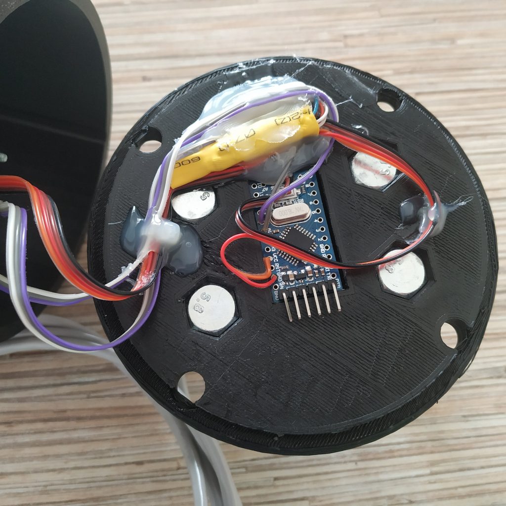
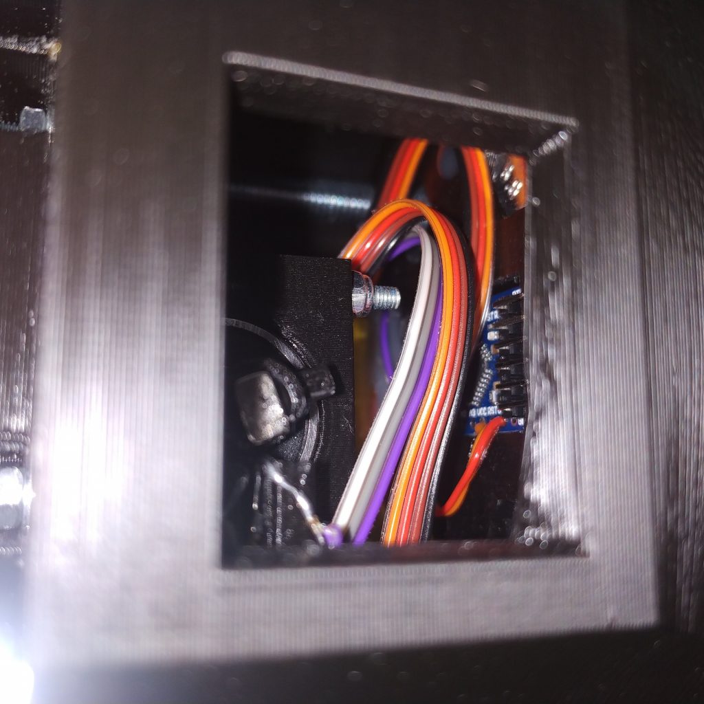
1) Here’s how the head looks from the inside:
http://hc625ma.org/wp-content/uploads/2018/08/P_20180824_213133.jpg
2) You will like that ribbon cable as soon as you will get your hands on it =) Trust me, having a lot of single wire cables in a tight space (when you do scale metal stuff in plastic, space is always tight) isn’t what you want, really, but you probably have to try it to understand what I mean =) That ribbon cable just makes cable management easier, bends well when needed, is cheap and compact.
Hello again, Alex! Thanks for your suggestions! I ran into some problems while assembling the alu pipe and screws (imprecise drilling, some broken thread…. have to dremel the screws *facepalm* but it’s absolutely permanently fixed now! *lol* ).
The picture is very helpful! And after experimentally tinkering around with the parts and some spare wires I totally get what you said about it being easier with ribbon cable! Would you mind posting another picture? I would love to see the “underside” of the completed AB412head connected to the throttle – I need to see the cable routing.
As always: Thanks for your suggestions! This is the most fun tinkering project I did so far!
That picture was the completed head =) After that, you just put some duct tape around Arduino pro mini’s pins and stuff things into the enclosure =) As for cable connections inside of the “i2c_conenctor_housing” part, you just leave a bit of spare cable (ribbon and ethernet) there, solder 4 wires, again stuff things into available space so they won’t protrude, that’s it =)
Or do you mean how the ethernet cable enters the head?
http://hc625ma.org/wp-content/uploads/2018/08/P_20180825_010920.jpg
The same thing with a Huey head:
http://hc625ma.org/wp-content/uploads/2018/07/20240005.jpg
There’s a TJ8-8P8 socket pressed fit into the corresponding slot in the head.
I am happy you’re enjoying building the lever! =)
Hey, those are great pictures! Now that part is also clear to me, thanks!
Unfortunately I hit another unrelated snag. Please see my image gallery (the bottom 3 pictures illustrate my problem): https://imgur.com/a/fjzrTKn
I’ll try my best to describe: The throttle grip has a little long tube inside. On one end that tube slides over the potentiometer “pin”, the other end goes into the “throttle_frame_p2”-part until the “upper end”. Now if I insert the alu pipe into the “throttle_frame_p2”, there is not enough room inside to also fit the little tube into there. It’s also impossible to fix the alu pipe inside the “throttle_frame_p2” because the screws will go right through the little tube.
So here I am, scratching my head, obviously missing something totally obvious. Please help! 🙂
Dont worry, that long tube is just the built-in support for the part! Different slicers handle supports in a different way, so its here to make sure nothing will go wrong. Just remove it, it should break easilly off the part that connects throttle grip with a cylinder ) I have to say though, you’ve done a bad thing – connected throttle frame parts without the throttle grip. It will be really hard to take them apart without breaking throttle frame p1 =(
When attaching the throttle grip to the pot, push it with something by its inner central cylindrical part, not by the outer one. You may want to shape pot’s handle to the form of a cone for easier fit. Also, i advice you to resolder that pot – these wires will break sooner or later for sure, they may also touch pot housing, which will grant you various weird effects)
Looks great otherwise!
I tried your suggestions and it worked! After resoldering the pot cables, I filed the inner tube so it would fit very tightly over the potentiometer “pin”. Then I threaded the cables as you showed in the video, and put everything together.
Luckily the screw which goes through the “lever_connector”-part was the only one I didn’t ruin! So it was no problem to remove the rubber bands holder and put in the M4-nut.
I used the inner tube to push into the potentiometer pin, then I simply broke it off. You were right: It was easy to remove!
Against your advice, I wanted to try it with a stripped ethernet cable. I managed to thread the wires through without problems. Now for the electronics part. I will have to contact you with questions regarding that. Until then: Thanks and all the best!
Thanks =)
Happy to hear you’ve been able to build the lever without too many problems =)
One bad thing about ethernet cable, it can break if you bend it too much. Let’s hope everything will be fine (anyway, it’s easy to replace if something goes wrong).
Electronics part is really simple: basically, you flash it, calibrate by adjusting map function values, and it works =)
I hope that you are right!
About the electronics part: Would you mind taking a look at my gallery (last picture) or this direct link -> https://imgur.com/2pwE8G0 . Because I tried parsing your instructions and coming up with the correct wiring scheme. Would you mind telling me if I understand it correctely and that is the proper wiring? Or if I am planning it wrongly?
Meanwhile I will be moving over to the AB412 head section and starting my stupid beginner questions there…. (insert facepalm emoji here)
Cheers!
Almost right! Two errors in your drawing:
– Throttle goes to A1, SS495A goes to A0 (it’s better to follow the default scheme so you won’t need to remember anything in case software will be updated, it’s SUPER important for heads =) )
– colors in the ethernet wire that are used are white-orange (5V), orange (GND), white-green (SCL), green (SDA), in that particular order from left to right while holding the cable with wire looking at you, contacts facing up (look at your ethernet cable). Why? It’s your standard ethernet cable crimping scheme (EIA-568B standard), it provides an additional reference for you to avoid making an error in the wiring. Also, you can use an ordinary ethernet cable for connecting stuff.
Note that you may need to press the reset button on Arduino pro mini when it says “waiting for a programmer to respond” or something like that to flash it. Also, note that the head has 2 arduinos in it.
Oh man, I knew I shouldn’t draw this when totally exhausted and tired…. Yes, I drew blue/white instead of green/white because of….. reasons, I guess….. ¯\_(ツ)_/¯ 🙂
About A0/A1: I am a little confused, because on the simple collective page there is written ->
“A0, A1 SS495A and potentiometer signal wires (A0 – throttle, A1 – collective, or change this in the ino file)”
Now you say that it is the other way round. Actually I don’t mind, but I just want to make sure that there is no misunderstanding.
One last question: What is the reason for you choosing to route the connecting ethernet cable through a hole in the base of the collective? I am pondering putting there another RJ45 connector to make it more modular.
These sockets cost some money (when you puy 1-2 pcs) and can be hard to find, and there’s not much point in detaching this particular cable anyway. I will make a mod in a couple of hours, no problem =) As for the manual, I will fix it and check this part in the code. It’s better when unified =)
I see your point! However I bought those parts in bulk at Aliexpress so I have a few spare ones lying around. No need to make a mod though, my trusty file and me will modify the existing opening. Had to file most other parts for hours already, so I am quite confident that I will fix that in no time!
By the way, I think I found another typo, this time on the “twin engine collective” page. In the step #32 you write:
“32. Route ethernet cable through a hole in the bottom lid of the enclosure and solder white orange wire to 5V, orange to GND, white-green to SCL and green to SDA wires, then solder everything to corresponding pins of the Arduino””
Shouldn’t SDA be “blue”? At least according to all the other pages.
Cheers!
OK, I made another attempt at a wiring schematic. This should be correct now: https://imgur.com/EtnXEpd
Yup, this one looks good! Note that you can also power the pot and SS495A from VCC pin, whatever you like more.
Thanks for finding errors, will fix them!
Hello again! I am finally back at it, finished the mechanical construction and soldered the wires according to the sketch you approved. Had a hell of a bad time sorting out PL2303 driver problems, and learning how to connect and flash the ProMini correctely – but your youtube video helped! Unfortunately the collective is not working as it should and I am back to scratching me head again:
1) When calibrating, where should the little “arm” of the “magnet_holder_5x5mm_socket_single_collective7a”-part facing?
2) After much fiddling and flashing the pro mini about 20 times I manage to get a range of about 205 to 1170 on the collective. Is that correct?
3) The map function does not seem to work properly. Even when using the syntax “z = map(z,205,1170,1023,0);” and checking in joy.cpl while moving the collective through the full range the displayed movement range is about 30% to 100%. What am I doing wrong?
4) The throttle worked once with a range of maybe 23 to 350 but after flashing it now moves from around 70 downwards through zero to 63650. It seems obvious to me that this can’t be mapped properly, and when testing in joy.cpl the throttle does not react to inputs.
I am fairly confident that I soldered everything properly this time and that there are no cross currents. But I will have to check again.
Do you have any ideas where I should start troubleshooting this? I have no problem fixing the mechanical problems, but the electronics stuff is really frustrating to me…
Hi! No worries, we’ll fix it.
1) The little arm should point towards the rear end of the lever (you can turn the magnet holder with it), the open part of the holder should face the magnet.
2) Comment map functions out before printing raw values! (that ADC is a 10bit one, so it can’t output more than 1023) Then, while looking at Serial.print output, move the collective to its lower position. Rotate the holder until you will see 0 on Z axis =)
3) I think #2 will solve this as well =)
4) again, that’s because you haven’t commented out map functions. If you will have 63650 after everything is done right, that may be because of resistor jitter. Increase its range in map function (e.g. if your raw values are from 3 to 705 try rz = map(rz,2,706,1023,0)
Thank you so much! You were 100% correct: I forgot the step where i should comment the map function… *insert facepalm* OK, the collective range works perfectly now! Yay! This is great! I flew around a bit in DCS and it was wonderful, even though I have no chair-attachment yet and had to lay the collective down on a chair next to me! 🙂
I did the same to the throttle but that part is not working completely: The raw range is 860 to 993. Seems a little small to me… I still inserted those values into the map function: map(rz,860,993,1023,0). However, in joy.cpl the throttle movement seems to me kind of like an exponential curve??? For 1 quarter of the travel there is no reaction at all then for 2/4 the raise is slow and in the last 1/4 the raise is very fast. Weird. I’d appreciate your input on this.
I also wanted to kindly ask you for a mod to the chair attachment – where should I post about this? I tried to do it myself but I am more of a musician/hands-on guy and getting my head around Fusion360 will take way too long.
Hmm, are you sure the pot is wired correctly? The middle pin is usually the signal one. Looks like you may have connected it like an SS495A =) The raw range should be something like 0 – 800 (200 deg of 300 available). The resistor should be of type B (linear, they usually have it written as B10K or B5K or A10K on them), but it will have somewhat the same range anyway. A means exponential voltage output.
About the mod – no problem, I will need dimensions of your chair =)
P.S. I am really glad you enjoyed flying with it! =)
You may be right…. I looked at a few websites explaining how to wire a pot and and it it possible that I somehow mixed up VCC and signal wires during soldering. Oh man, I am terrible at this. Will have to check it out.
One more thing: In joy.cpl I have 3 “Arduino Leonardo” devices. Is it possible to give them individual names like “Simchair MK2 Collective” and “SimChair MK2 AB412 head”?
About the mod: I think that I could attach the collective onto my chair with a slightly modified “ikea_gunde_frame_collective_frame_mount_left_150_deg_ikea_gunde_frame02” and “ikea_gunde_frame_collective_frame_mount_right_150_deg_ikea_gunde_frame03″ part together with 2x”ikea_gunde_frame_frame_mount_back_part_ikea_gunde_frame04”. However I would need the first two to be not angled but instead vertical.
Here is a picture I made of my current sim chair: https://imgur.com/76yOkKx
Flying is a blast and who needs a throttle if you can adjust rotor blade angle! Thanks for your help!
Sadly renaming joysticks is not possible as far as I know =(
But these joysticks are placed in a persistent order, all axes and a stick are on the 1st one, heads are on the 3rd one, the second one is for some special stuff.
I think making a mount for this chair won’t be a problem at all =)
Will try to do it as soon as possible when time permits.
You should try flying something like an R22 or Schweiser 300 without the governor, that’s where the throttle is most useful =) Or turn it off in a Huey and try flying formation while keeping needles in green, that’ll make you sweat for sure =)
Thank you! This is a long term project for me and I don’t mind waiting. Am very glad that you are willing to do this after all.
And I don’t think formation flying with or without governor would be a successful operation. I am glad to stay within the countries boundaries when trying to hover during the landing phase. 🙂
So, I finally had a little time to myself and I flipped+resoldered the VCC and Signal wires on the potentiometer. And suddenly it is working perfectely! I could calibrate it and the axes work in joy.cpl like they are supposed to!
YESSSSSSSSSSS! I made something that actually works! I could not have done it without your help. Thank you SO MUCH!
Next thing I’ll start is the AB412 head and an extension for my Saitek X56. So you will hear from me soon on the AB412 page.
Peter, here’s a mount for your chair:
https://github.com/hc625ma/simchair_models/tree/master/Components/Frames/Generic%20Chair%20with%20vertical%20round%20legs/STL
Let me know if it worked =)
That’s cool! You’re welcome! =)
Have you calibrated it with the map function, just as the collective axis? Joy.cpl software calibration after map function can slightly reduce precision =)
I will be working on a spherical bearing based cyclic gimbal soon, I think it may be a lot better than Saitek one (the idea is to make a gimbal that will support springs and force applications).
Also, I am testing quite an interesting rubber-bands removal related mod for the lever =) If nothing breaks under load in a while, I will post it, flying with it feels great.
Your questions are welcome =)
Cheers
WOW! I am super impressed with this system you’ve created! I’m going to start building it and am going to have to learn a LOT on the way, but I’m very excited! Just curious, on your thingiverse it says you’re an engineer, what type are you?
Thank you, Ben, please feel free to ask questions here if any =)
I am a system administrator/programmer/electronics engineer, something more, something less =)
Hello again! Thank you very much for the new mount! I already sent the files to the guy who has a printer and will report back on my misadventures. 🙂
That’s cool, I hope everything fits together =)
Check out a new pneumatic mod for the collective, it feels great!
Hello again!
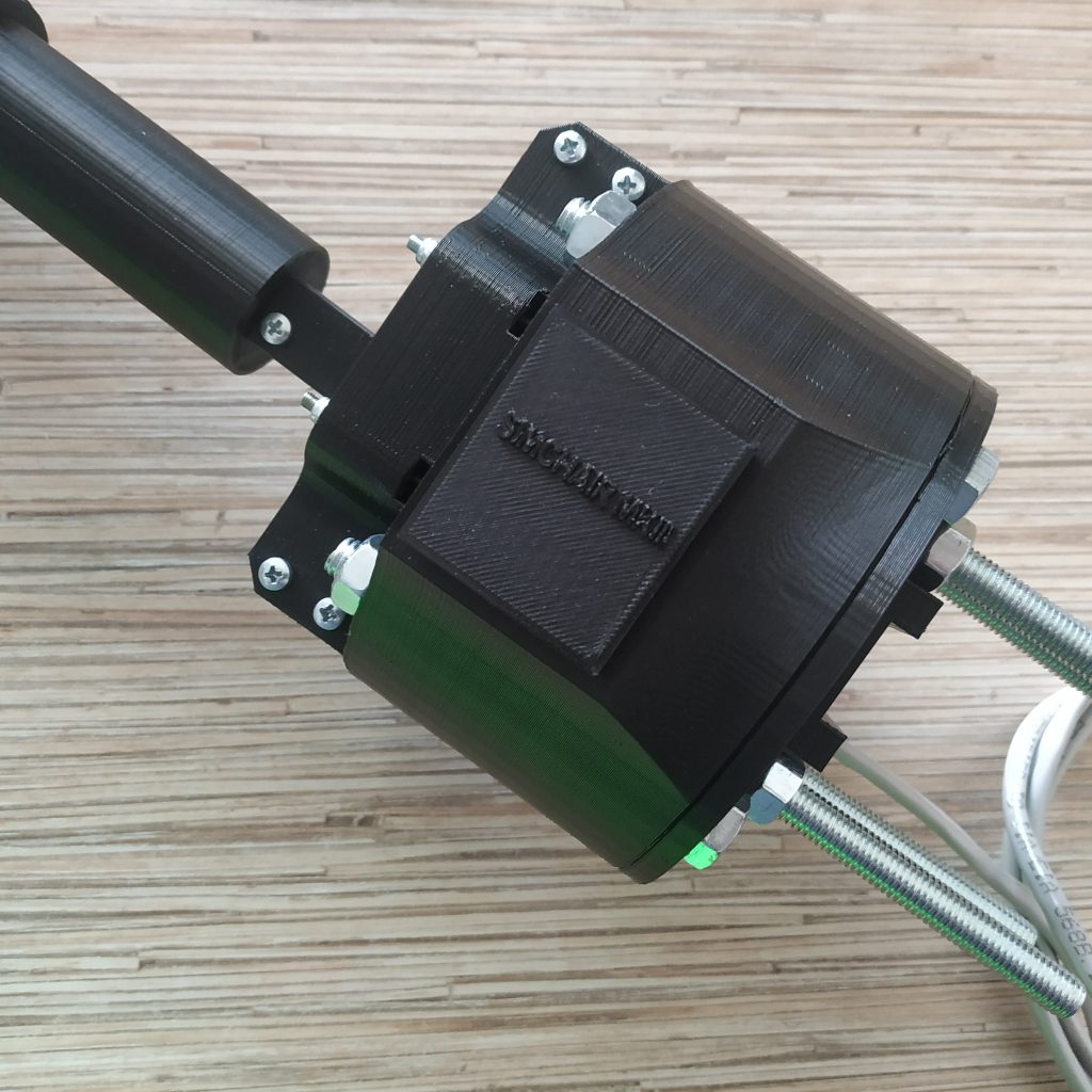
Here is a gallery of my progress and the finished single engine collective lever: https://imgur.com/a/fjzrTKn
Now I will move onto the head part. Thank you so much for all the help!
Everything looks great! Will adjust that mount (it may be that bolts in different countries can have slightly different secondary parameters like head height). I strongly advise you to try the pneumatic mod- can’t really imagine flying without it anymore =) I have to say that, with or without the cylinder, a counterweight works better than rubber bands.
I am now working on adding proper photos to every manual, hopefully, will add photos for the 412 head and a pneumatic mod in a few days.
http://hc625ma.org/collective-pneumatic-mod/
That’s great! Feel free to use any of my photos and modify them in any way you deem useful. I would love it if I could provide something useful.
Thank you! I will definitely post a link to your gallery on the single collective page =)
Hello,
First and foremost, thank you for taking the time and effort to host all of this to us. The helicopter community suffers in terms of affordable and realistic peripherals. Your work is truly a blessing to those who want to take the route of DIY but don’t know where to start. You provide all the necessary beginnings for us to truly make ourselves a quality experience. So thank you very much for that.
Regarding the printing, i see you use PLA and don’t recommend we use ABS to print with. How have your prints held up? My only concern about PLA is the possibility of it breaking down in just a year or two due to moisture changes in the air, and due to handling without gloves on for prolonged periods. Have you tried to use nylon or POM, or would that also mess with the print ?
Hi! You’re welcome =)
The problem is, every material shrinks differently. I had no problems with PLA so far (even with the VR Max head which is quite heavy!). Maybe in a few years, something will break, but then, you can simply print a spare part. Everything is designed to be repairable and serviceable, and by the time it will break, there will probably be some nice upgrades that you will want to install. I also have a printed 450 size RC helicopter, although the rotor assembly from a Trex clone is used in it, the airframe, printed in PLA, still holds together after 2 or 3 years. The only thing, don’t leave it under direct sunlight for too long, especially if it’s in black =)
Your m4 screw is both not listed in your components list and also the wrong length in the guide. Looks like I’ll have to wait another week to finish this. 🙁
By my estimate you need a M4x100mm or M4x110 to connect the two halves of the throttle frame together.
Hi Connor! Thank you for noticing that it’s not listed – fixed it! But you’re wrong about 110mm, you need exactly an M4x80mm screw. You have to press-fit a nut into the socket. Use something long, like a Phillips head screwdriver.
Unfortunately that’s not the case, maybe something is wrong with the files I downloaded.
Check the image below of the 3d models for p1 and p2 of the throttle. The blue lines are where an 80mm long screw reaches to and the red is where it needs to reach to in order to even begin threading.
https://imgur.com/a/j4q8Xzx
Maybe I’m missing something?
Wow, looks like you’re right! Looks like an M4x110mm screw will be ideal. I wonder where the 80mm one appeared from then 😀 Thanks for pointing that out! Will fix.
Hey there,
I designed KA50 pedals for your helicopter pedals. They are T-shaped. The 608zz bearing is on the lower half of that T shape. The top part of the T is the actual footrest. I am trying hard to figure out a way to keep the pedals perpendicular to the MIP whilst pushing the pedals. Any ideas?
Thanks in advance.
Hi Felix! That’s cool!
Can you send some pictures to me? Maybe I will have some good ideas =)
What’s MIP? These pedals look more like plane-type to me, moving forward-backward rather than rotating up-down at an angle, maybe improved mark2 design will work better in this case?
https://cdn.thingiverse.com/renders/54/2d/ce/4e/8e/e862cf3262d391736274904a32638462_preview_featured.JPG
Cheers!
Hey there, check the pictures down below.
Is the Mark 2 design still work in progress? They would perfectly fit my needs. I could also use the actual ones though. The Mark 2 design also has the problem of footrests not moving at the same angle. Maybe we can work something out. Could you write me an email? Makes communicating alot easier 🙂
Now the pictures. Note that I have commented the pictures.
https://imgur.com/PMVOkNE
Greetings Felix
Sorry folks. First post didn’t quite work out. Here’s the full gallery: https://imgur.com/gallery/Vhosm77
That’s cool! I will write you =)
The MK II is an old design, it’s also nowhere close in regards to documentation – but these pedals worked, so you can just use them as is =) Note that you will probably have to adjust tolerances for PLA (parts were designed with huge ABS shrinkage in mind)!
https://www.thingiverse.com/thing:1578566
Cheers!
Hello Alex! I have been flying with my collective for a while but now unfortunately I am facing a problem that I can not solve on my own, even though I spend hours trying to learn the necessary skills…..
After having to buy a new sim chair (old one broke down compeltely due to….. reasons), the beautiful modified attachments you designed for me no longer fit. So I decided to improvise a floor mount (basically a heavy plank with an angled near-vertical 20×10 rod to which I want to attach the collective).
In order to do that I need the attachment part on the collective rotated by 90 degrees, and also the “wire hole” modified to be rectangular to fit a RJ45 port (without blocking the aluminium rod of the screws). Like in this image: https://i.imgur.com/YZky4dX.png
I tried to edit this .STL file in Fusion360: https://github.com/hc625ma/simchair_models/blob/master/Components/Peripherals/Single%20collective/STL/single_collective_enclosure_bottom_p1_twin_collective02.STL
However I am totally unable to grasp how to edit this stuff in Fusion, I tried hours of tutorials and can’t even make a proper box, let alone cut out parts and rotate them. 🙁
So I am desperately asking you for help with a modification of that STL file. Would it be possible for you make those edit for me?
Regards
Peter
Hi Peter! No problem will try doing it today in the evening =)
—-UPD—-
actually, I think it may be better to use the newer pneumatic mod compatible back! It will be the new default for 4th gen as well – just so no one will have to swap them in case he/she will want to add pneumatics later =)
You can simply mount it to a vertical stick as is!
Thank you for your generosity and time!
Do you mean this part? https://github.com/hc625ma/simchair_models/blob/master/Mods/Peripherals/Collective%20levers/All%20levers/Pneumatic%20actuator%20mod/STL/pneumatic_mod_enclosure_bottom_p1_pneumatic_mod01.STL
I am a bit puzzled about which side is up, but if you say that I can mount it to a vertical 10mmx20mm rod, then I am golden! Would it be possible for you to modify the wire hole so I can put a rj45 socket there without interfering with the alu rod and screws?
I figure that I would also need this part: https://github.com/hc625ma/simchair_models/blob/master/Mods/Peripherals/Collective%20levers/All%20levers/Pneumatic%20actuator%20mod/STL/pneumatic_mod_enclosure_bottom_p2_pneumatic_mod02.STL
Yup, also this one: https://github.com/hc625ma/simchair_models/blob/master/Mods/Peripherals/Collective%20levers/All%20levers/Pneumatic%20actuator%20mod/STL/pneumatic_mod_enclosure_bottom_p3_pneumatic_mod03.STL
You can mount it fitting the rail between p2 and p3, leaving the horizontal rail socket unpopulated =) The new MK IV version has 8mm holes in angles of a square, so it can be rotated as you like, but you’ll need to reprint the base to upgrade to it. But, it actually may be worthwhile – pedestal support, seriously improved durability and precise metallic axes (you will need to get 18x8x6mm threaded hubs somewhere)!
And I highly recommend getting one of those MAL16-100 cylinders- you’ll like the feel!
Will try fitting a socket into both versions (may be a bit tight on space though!) =)
Here, try this one!
Thank you very much for your generosity and time. I will download try getting this printed. Thank you again!
You’re welcome, mate! Let me know if you need smth to be adjusted.
Hi, really nice setup you have put on here. I’m currently building one for myself.
Was wondering if it is possible to switch the Arduino Pro mini with an ADS1115 16-bit ADC, so you can get more precision out of the SS495A hall sensor. My doubt is if it as simple as connecting:
SS495A1 signal -> ADS A0
THROTTLE POT signal -> ADS A1
Ethernet socket pin 3 (SCL) -> ADS A3
Ethernet socket pin 4 (SDA) -> ADS A4
and getting the SCL and SDA signals out of the ADS1115…
Or maybe just combine the SCL and SDA outputs from the ADS1115 with the ones coming from the ethernet cable:
SS495A1 signal -> ADS A0
THROTTLE POT signal -> ADS A1
ADS I2C SCL -> Ethernet socket pin 3 (SCL) -> new merged Ethernet socket pin 3 (SCL)
ADS I2C SDA -> Ethernet socket pin 4 (SDA) ->new merged Ethernet socket pin 4 (SDA)
Is something like this posible??
thanks for your great work!
Hi! Thank you for your kind words!
Well, yes and no =)
You can connect ADS like this:
SS495A1 signal -> ADS A0
THROTTLE POT signal -> ADS A1
ADS I2C SCL -> Ethernet socket pin 3 (SCL)
ADS I2C SDA -> Ethernet socket pin 4 (SDA)
However, you will need to change the code, and also, it won’t give you that much improvement!
Also, note that you will need to change the address of ADS1115:
If you look at my videos, you can see that filtered 10 bit is quite enough for the collective!
It’s easy to change the code – just look how it’s done in pedals =)
Let me know if you need more help on that.
—–UPD—–
Actually, I am curious, have you tried flying with it and found its performance subpar? It’s important because we might choose to go this way in MKIV, but I am not sure if we really should overcomplicate stuff?
—–UPD—–
Actually, I am curious, have you tried flying with it and found its performance subpar? It’s important because we might choose to go this way in MKIV, but I am not sure if we really should overcomplicate stuff?
—-
I’m in the building stage, so haven’t tried to fly with it yet…. but while building I thought why not go directly with the ADS1115 if it is just a a swap of circuit board (and little change of code afterwards…), I actually find it more simple stuff than the arduino board since its means 1 less board you have to flash program and its a smaller board.
I also modified/simplified the pneumatic mod to use a motorcycle steering damper anchored to the decorative cover and the main housing, so far looks good and simple. I will use a longer 10×10 aluminum tubing attached to the lever connector as your design but extending backwards for the counterweight, will modify the housing and the back lid with openings to allow this extension to exit the housing and move freely as you move the collective. Currently waiting for a new aluminum tubing to try this.
The thing is, you won’t be able to connect anything but axes to it. E.g. mode switch for a twin collective won’t fit. That means differences in a base part that in theory should be the same for all levers =) If we remove the mode switch, the simple collective will suffer. If we add a Pro Mini board as a 2nd board, we will make it more expensive, and having a whole Pro Mini board for a mode switch is fairly anal. Then the collective is silky smooth already with a filtered 10 bit ADC of Pro Mini, and it perfectly solves all of the mentioned problems =) That’s why it’s still there, although the ADS is more precise.
Would love to see some pics of your mod, looks cool!
Cheers!
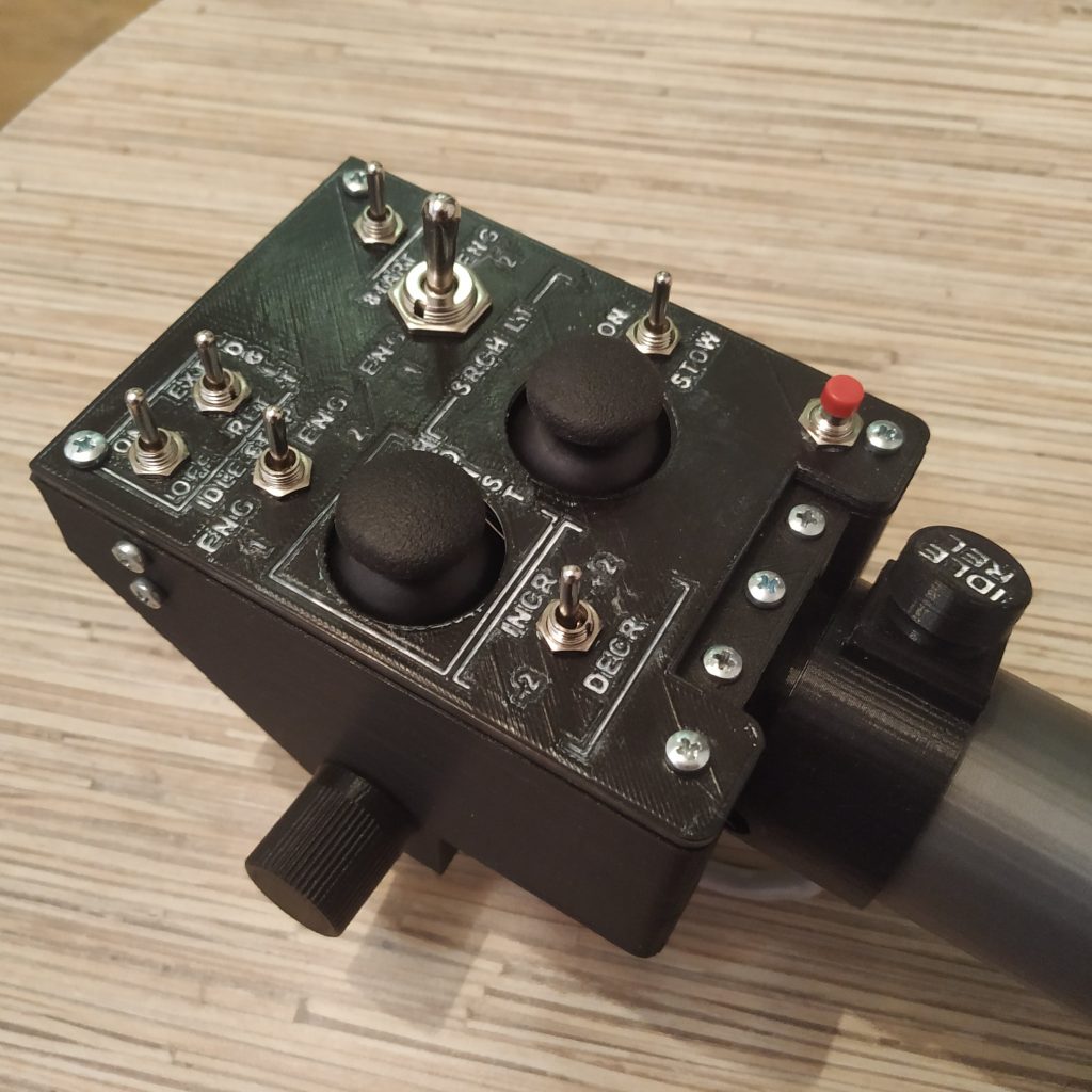
In the following link should be a picture of my collective up to now… still soldering to do in the AB412 head (note I tilted it a little)
https://imgur.com/oYxOipL
Looks great! What did you paint the letters with?
Painted the letters with white paint marker, then cleaned the over paint with alcohol pads.
Cool! I tried everything except alcohol 😀 It was very hard to remove, and working with acetone was a real pain as it was partially dissolving plastic as well. Thanks for the idea =)
——
The thing is, you won’t be able to connect anything but axes to it. E.g. mode switch for a twin collective won’t fit. That means differences in a base part that in theory should be the same for all levers =) If we remove the mode switch, the simple collective will suffer. If we add a Pro Mini board as a 2nd board, we will make it more expensive, and having a whole Pro Mini board for a mode switch is fairly anal. Then the collective is silky smooth already with a filtered 10 bit ADC of Pro Mini, and it perfectly solves all of the mentioned problems =) That’s why it’s still there, although the ADS is more precise.
——
My actual plan is to move the master controller inside the housing of the collective, I will be using an Arduino Pro Micro which is supposed to be a miniaturized Leonardo board (both use the ATmega32U4) and has similar size to the Pro Mini. The back lid will have 2 ethernet inputs for connecting other I2C devices to it (the third device is connected internally the the Master Controller: collective with Head), a USB micro port connected to the one the Pro Micro has for final connection to the PC, and the reset button taken from the MKIV design!
The difference with your design is that you have to modify the code in the master controller instead of the collective device in other to achieve the same functionality you mention… I guess… I still have to learn how to code for Arduino!
Yup, it can be done like that as well. I am working on an entirely new MKIV software now- it will be much better than MKIII version =) You will need to add some code to the Master, you can look at how it’s done with the cyclic gimbal or pedals.
This is all about learning electronics with fun, so it’s always good to try different things! =)
Hello again! I wanted to report that after grinding and sanding the printed parts for a while, it fit very well onto my existing collective base. I am now able to make a proper new attachment. Thank you very much for your time and effort!!
Hi Peter! Happy to hear I could help =)
Cheers!
Here is a picture of my Frankenstein creation. It’s ugly and janky as hell, held together with rubberbands (because I can’t be bothered to give a damn abot making it better). But it basically works. Thanks for the help!
https://i.imgur.com/L2diyxv.jpg
Actually, it looks good =) You’re welcome!
Hi, finally connected everything (with my ADS1115 and Pro Micro as master controller inside collective housing). Did some new coding for using the ADS1115 instead of a Pro Mini in the collective, modified the files: a_configuration.ino, b_main.ino, e_single_collective.ino and master_controller.ino.
Flashed the Pro Micro and got some readings in serial monitor for z (collective) and also for throttle… I’m having 2 problems:
1. The signal for both axis is not steady, they keep moving producing a small jitter.
2. When trying the windows calibration program I can only see the throttle shown as Z axis in the first arduino listed, there is no signal shown for the collective in any of the 3 arduinos.
I have no idea what’s wrong, maybe I just screwed things up with my coding (I copyed and modified lines from c_flight_stick_gimbal.ino, removed everything related to force trim). Can you email me so I can send you my files to see if you can detect where I messed things up?
Please look at MKIV firmware instead – it’s way better. Actually, to the point where you can add custom devices to it without losing compatibility with the master branch =)
https://github.com/hc625ma/simchair4_software
A certain jitter is natural and does not affect flying. It should look steady in joy.cpl.
will email you =)
Hi, Great work with the helicopter controls. Im currently building a single engine collective with the throttle latch mod. Now the inside of the throttle has had extra material fitted compared to the non mod throttle and now the throttle frame part 1 doesnt fit inside the throttle. I have searched for a modded throttle frame part 1 but cant find it anywhere. If you could please point me in the right direction it would be appreciated.
Lennie
Hi, thanks!
That extra material is a built-in support, just snap it off =)
Cheers!
Hello, absolutly outstanding job mate, im already in production and i love how everything is fitted.
But i have a question, you see im about to only use collective, as i already own joystick.
Do you think would be possible to use single arduino to control collective throttle and huey head? As making a controll box would take too much resource and space.
Regards
Hey Alan! Thanks for your kind words! Sure, no problem with removing the controller box, just put a pro micro board into the collective base box. That’s the easiest way to achieve what you want. On the other hand, the control box is actually quite small and doesn’t add all that much to the overall cost of the stuff =) You will still need a separate pro mini board for each device and the master board because changing the architecture will require a major software rewrite, which at the current state of the software is like re-wiring the space shuttle to save a few pounds of copper =)
Cheers!
I was wondering how much of a difference it would make using a round magnet 6×3. I can make sure it fits and is secure just as well as square one. Any thoughts on how this may or may not affect performance. I am having trouble locating magnets at that shape in good shipping distance and reasonable price. I already have strong round magnets at that size.
hi! Id depends on the polarization of the magnet. Try it and try different positions of the magnet – it might work well enough.