Summary
Components
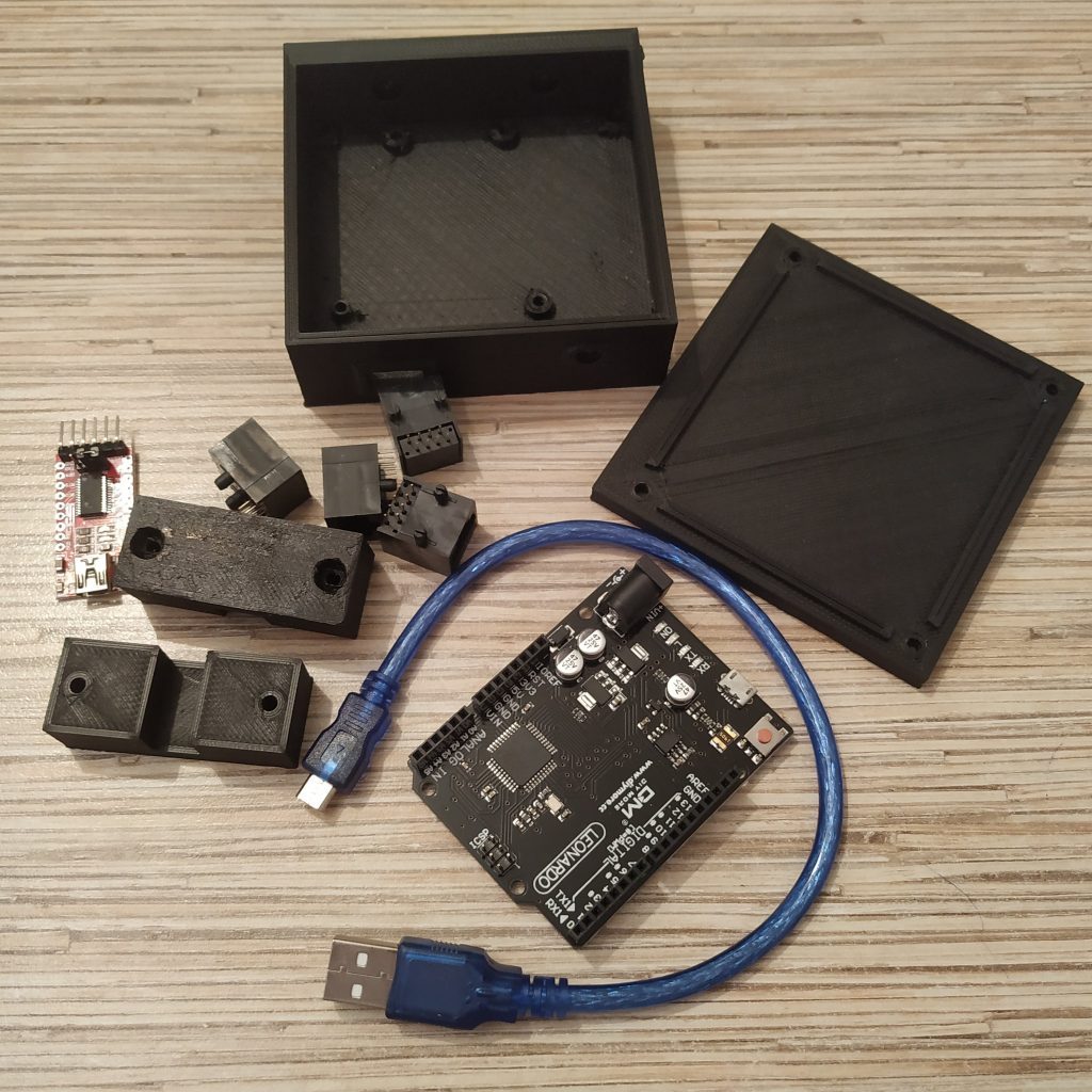
1 x Arduino Leonardo
1 x FTDI232 USB-UART board
1 x 6x6x5mm tact button
4 x TJ8P8C sockets
4 x M3x30mm screw
2 x M3x40mm screw
4 x M3x6mm screw
6 x M3 nuts
ribbon cable
Downloads
Assembling manual
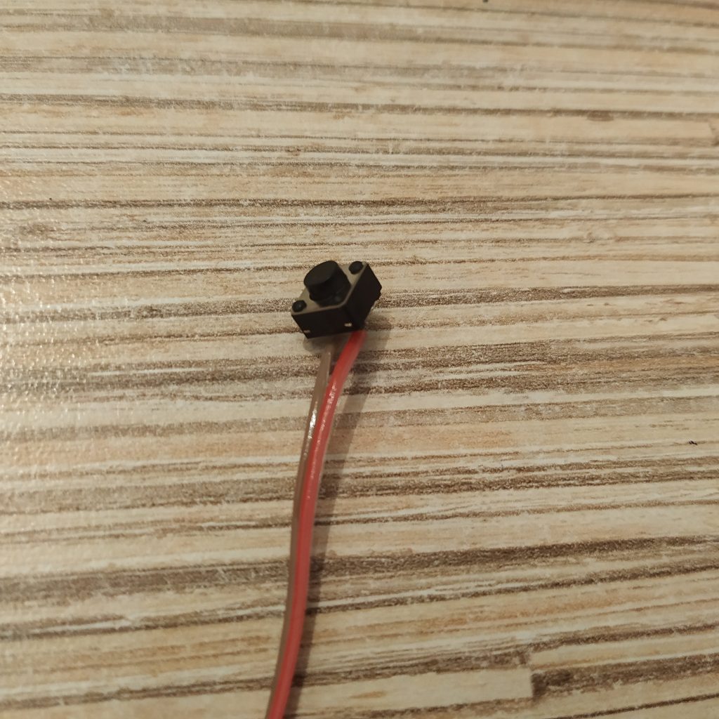
1. Solder reset button wires to a 6x6x5mm tact button.
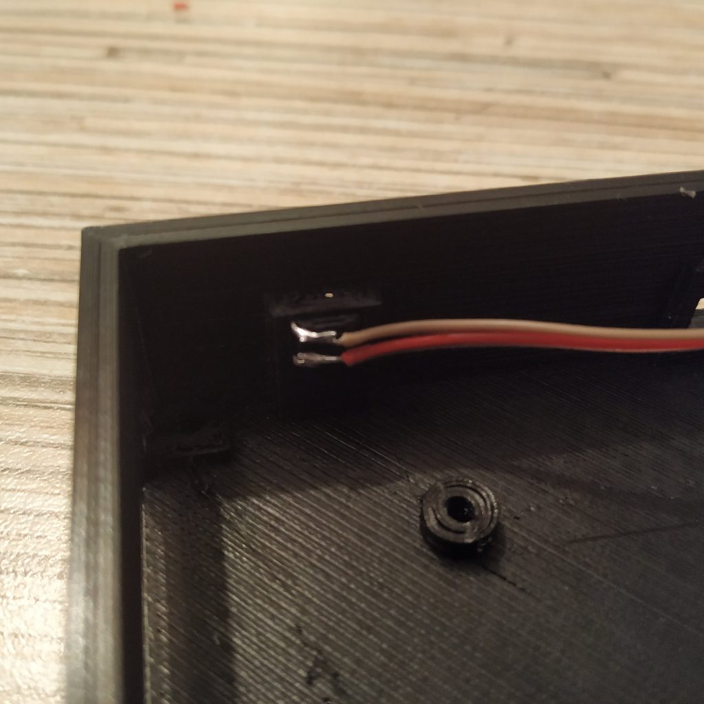
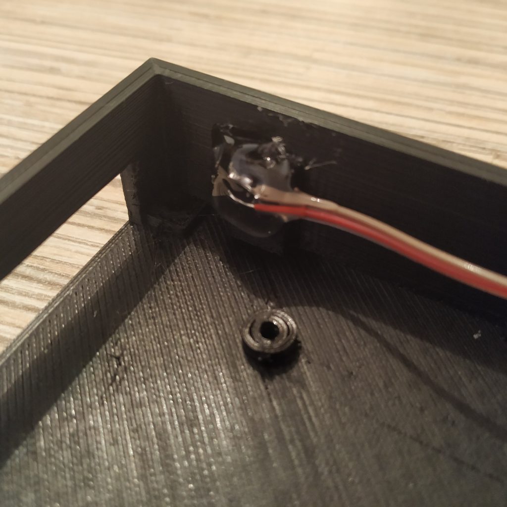
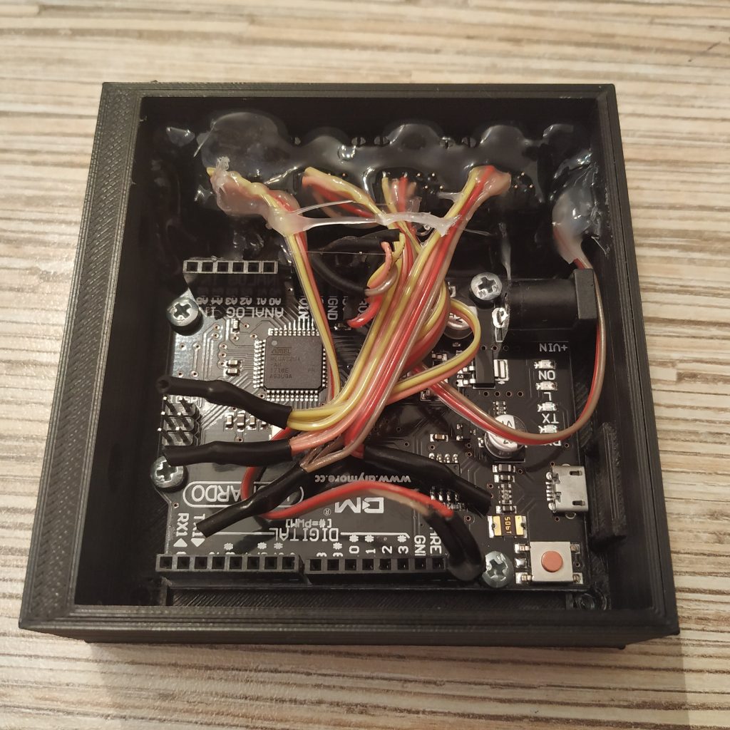
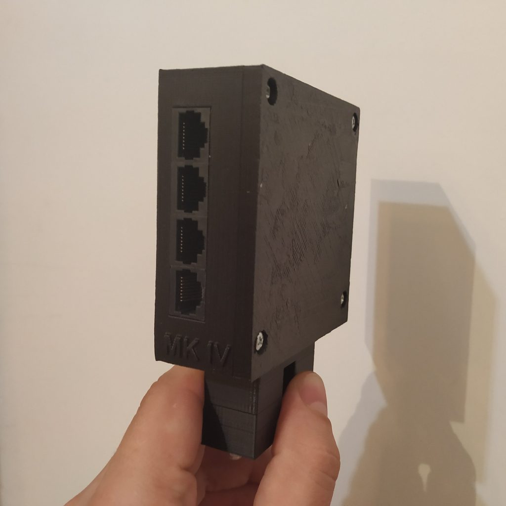
2. Put the RST button into its socket in the controller box, fix with hot glue.
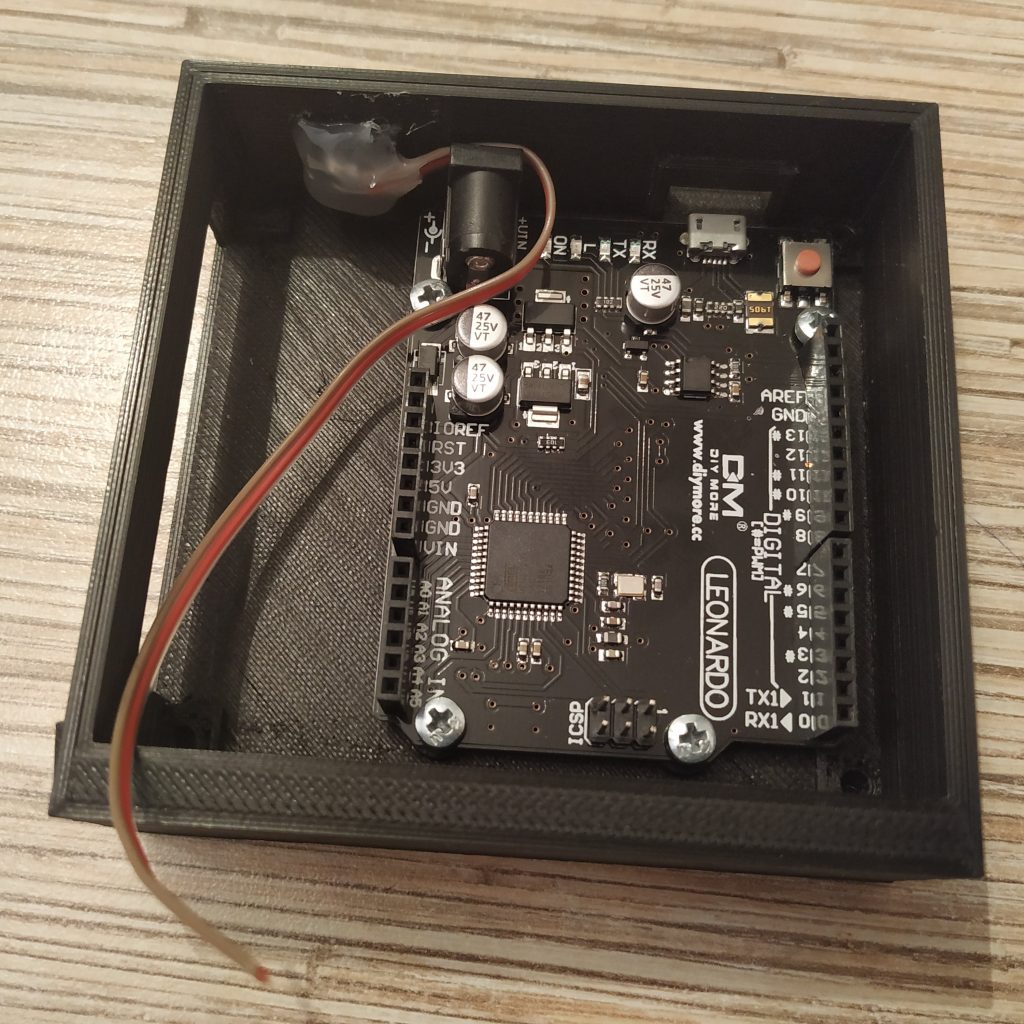
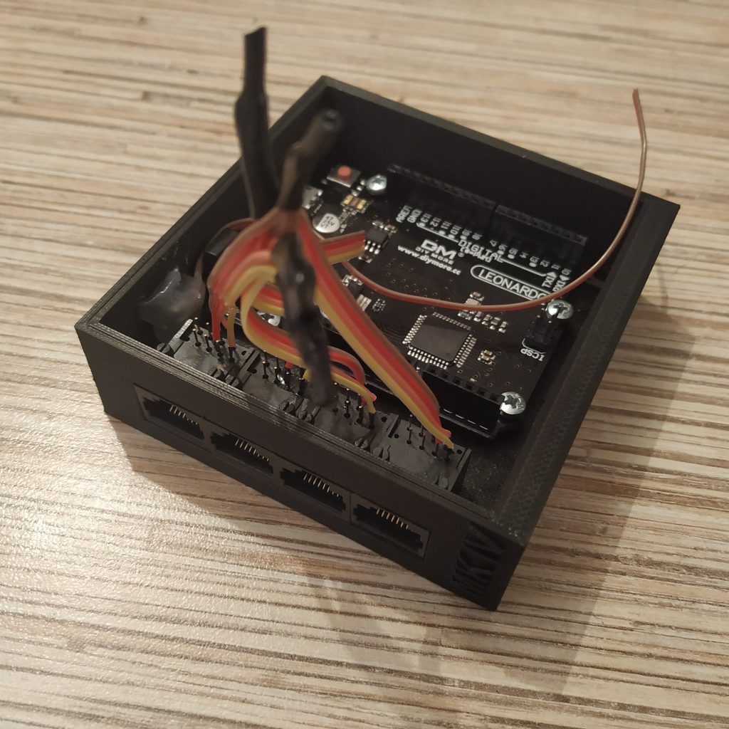
4. Put the Leonardo board into the box, fix with 4x M3x6mm screws.
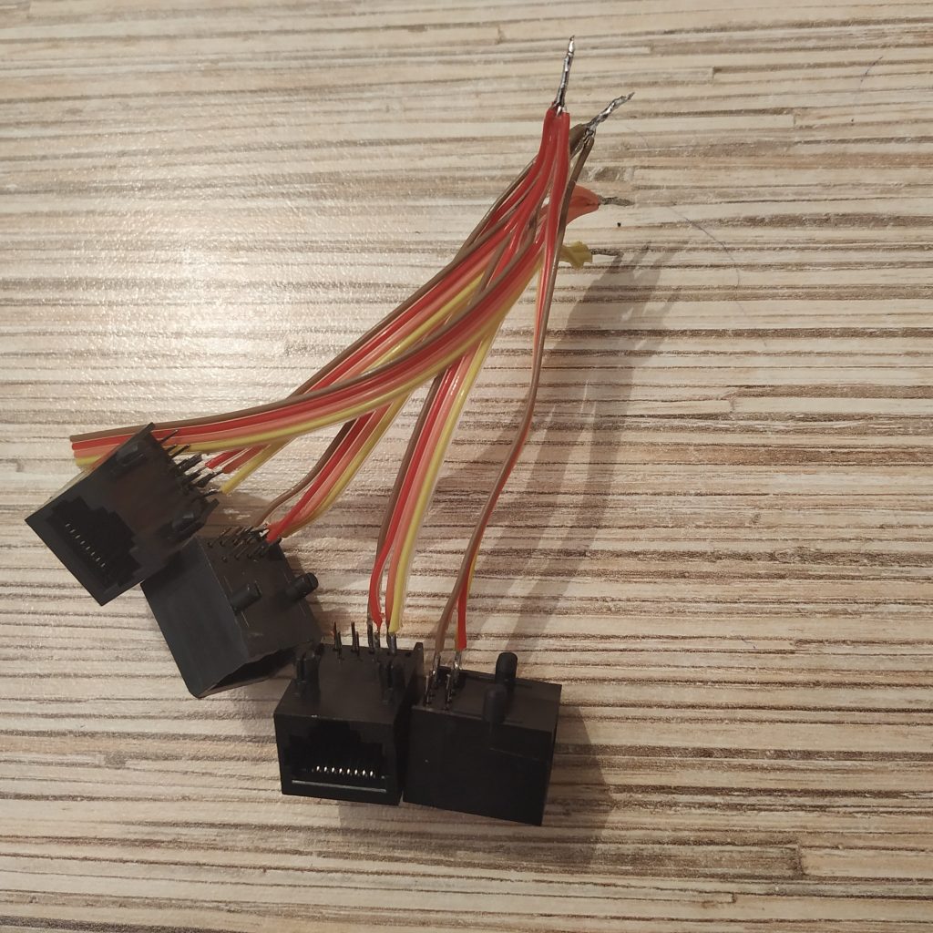
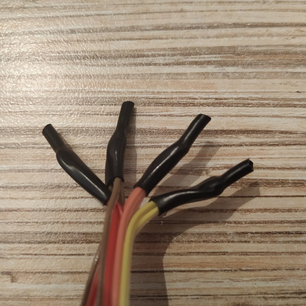
5. Solder 4 4-wire cables to Ethernet sockets, add 5th 4 wire cable and make a cable tie (tie wires of the same color together and solder them). Cover ties with thermal shrink tube. Pin 1 is where the white-orange wire of an Ethernet cable will go.
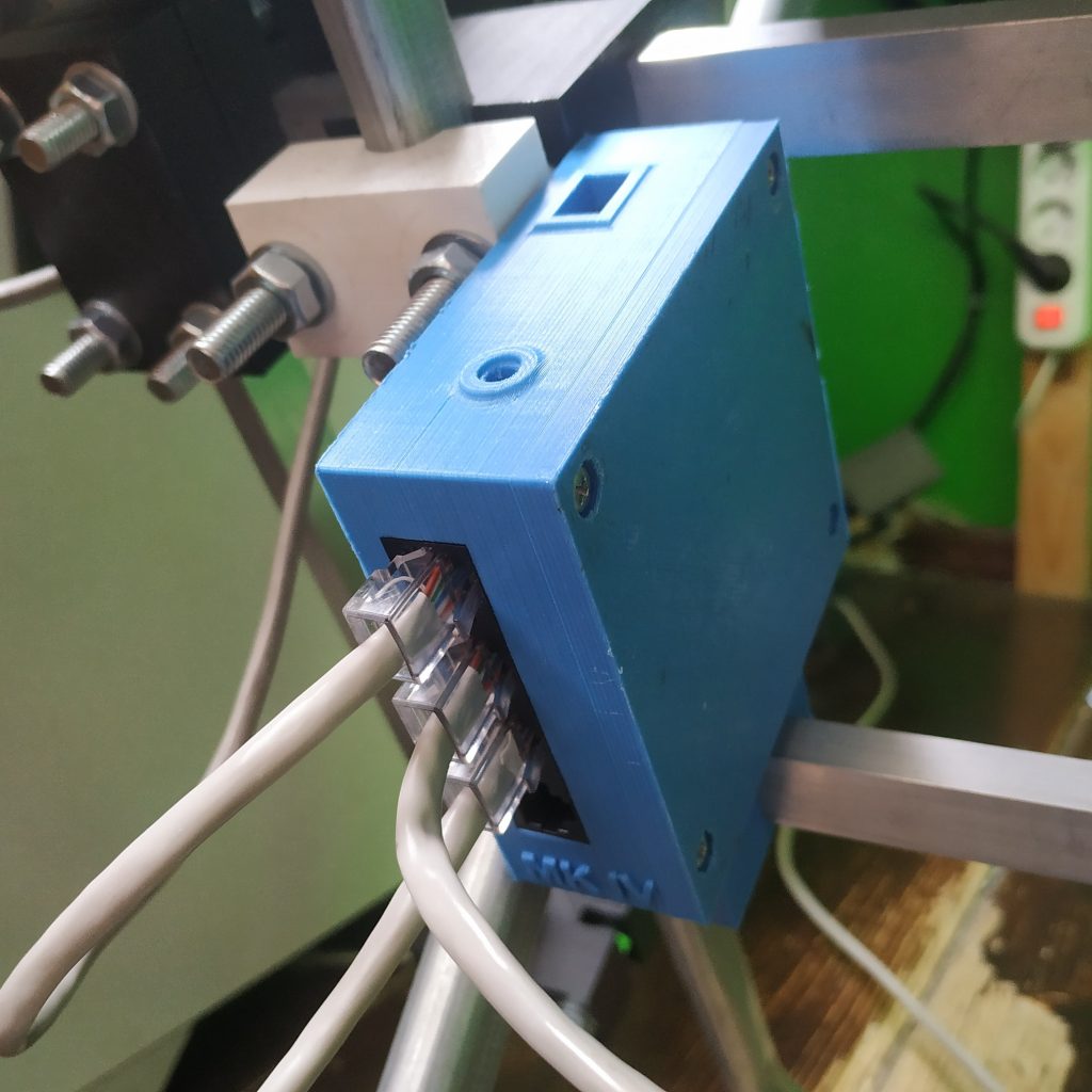
6. Put sockets into their slot in the controller box.
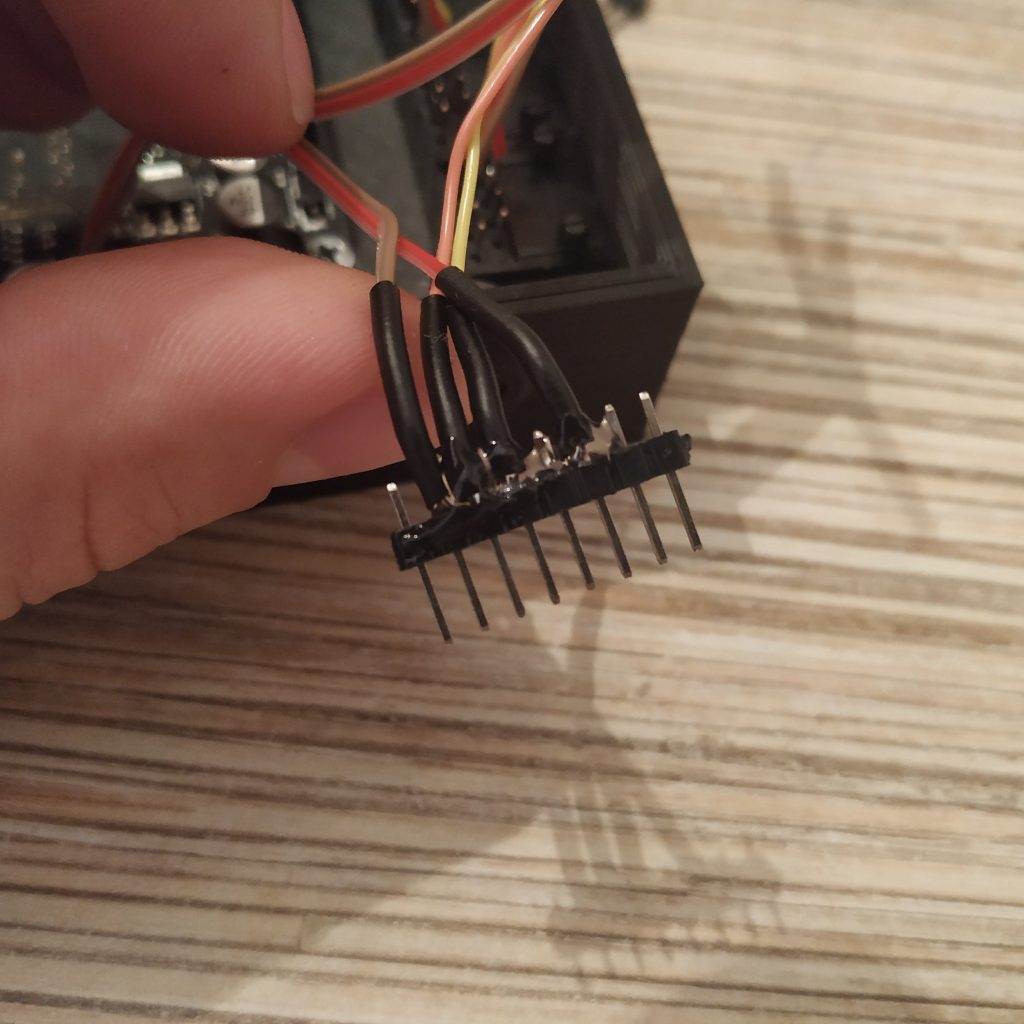
7. Cut an 8-pin connector and solder wires as follows:
- SOCKET PIN 1 (white-orange wire of Ethernet cable) -> 5V
- SOCKET PIN 2 (orange wire of Ethernet cable) -> GND
- RST BTN PIN 1 -> RST (polarity does not matter here)
- RST BTN PIN 2 -> GND
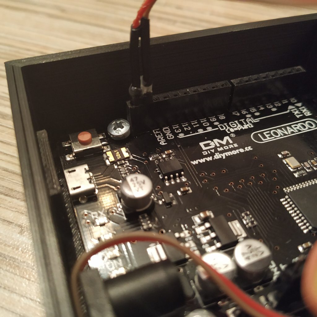
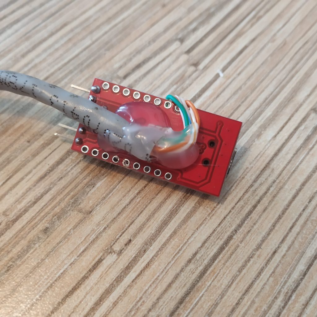
Put a thermal shrink tube and some hot glue onto wires to fix them. Insert the header into the Leonardo board.
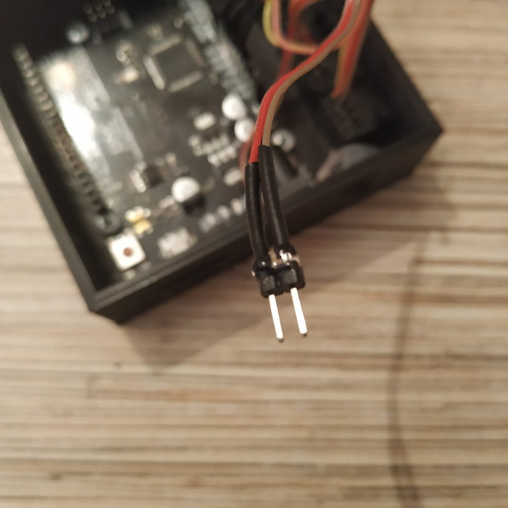
8. Solder a 2-pin connector to SDA and SCL wires and connect them to their sockets. SCL pin (Ethernet socket pin 3) is the closest one to RST button on the board.
- SOCKET PIN 3 (white-green wire of Ethernet cable) -> SCL
- SOCKET PIN 4 (blue wire of Ethernet cable) -> SDA
9. Flash the controller with the master controller firmware from simchair4_software repo and connect a peripheral to it to check if it works. Check every socket this way. If everything is fine, proceed.
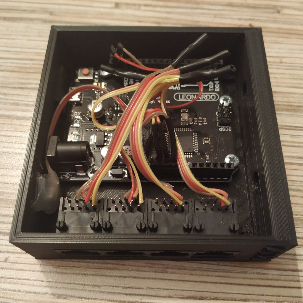
10. Do some cable management and fix sockets with hot glue. Be careful not to pour glue onto lid screw holes. Don’t worry if this happens though, hot glue can be easily removed mechanically after it will dry.
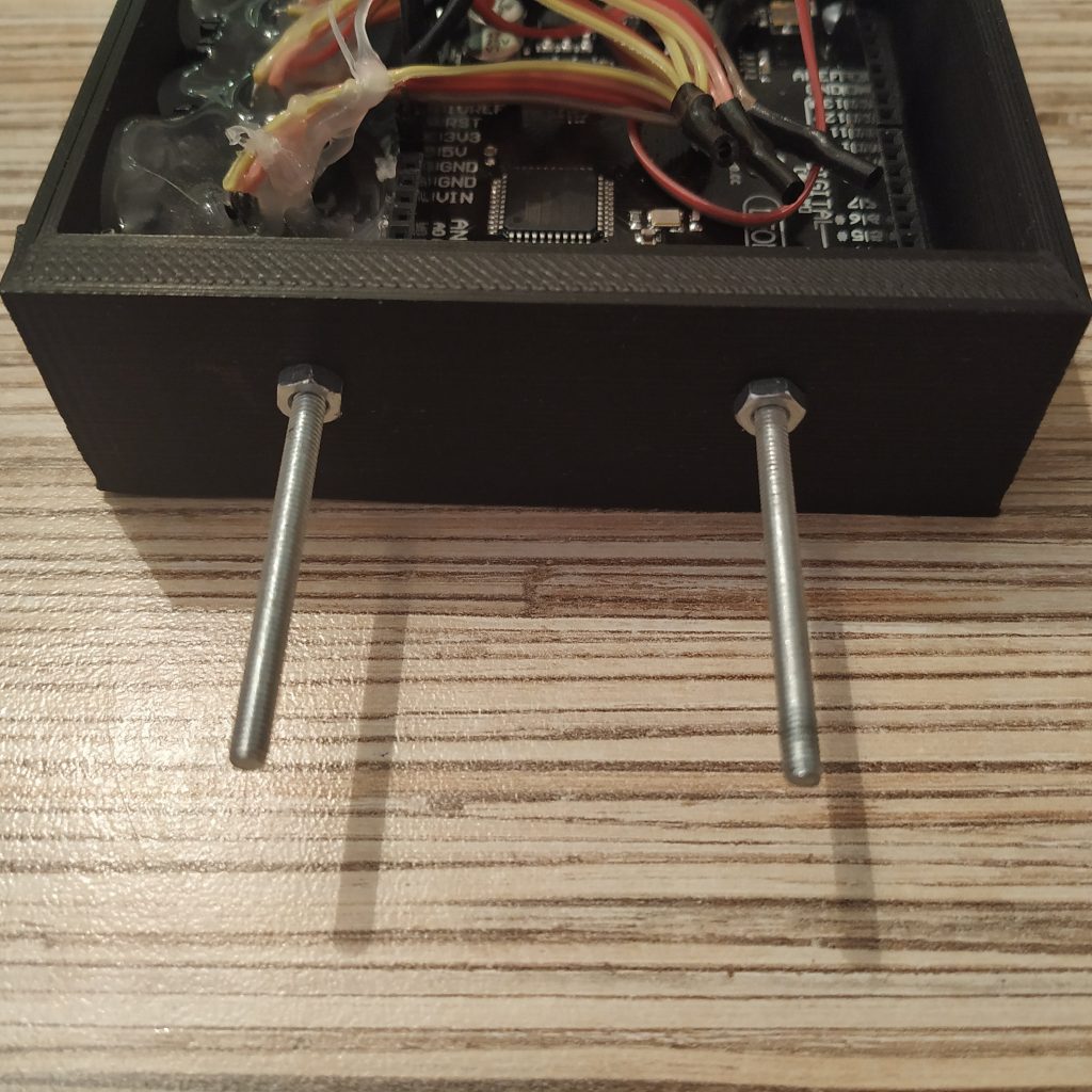
11. Put 2 M3x40mm screws into their sockets, fix with nuts:
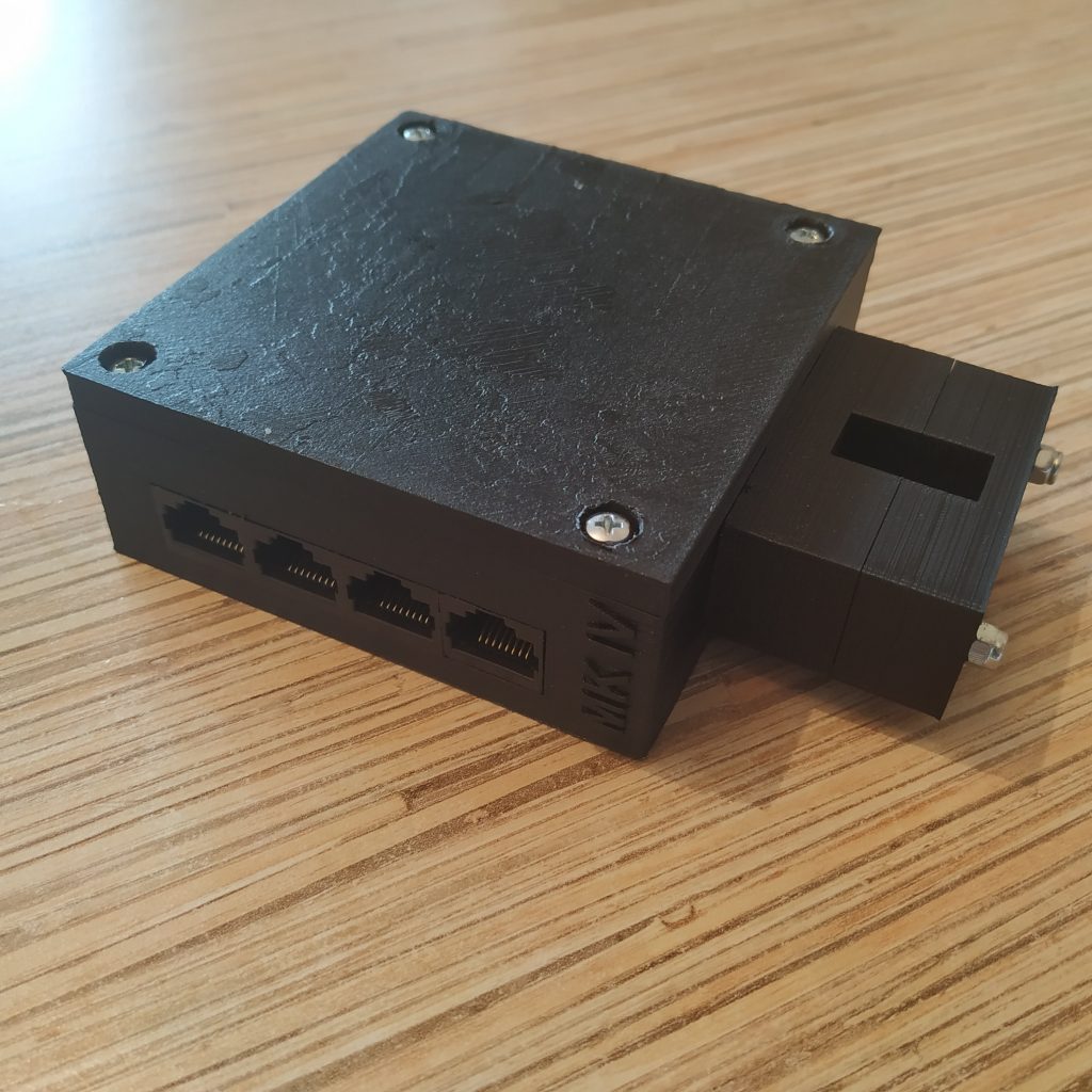
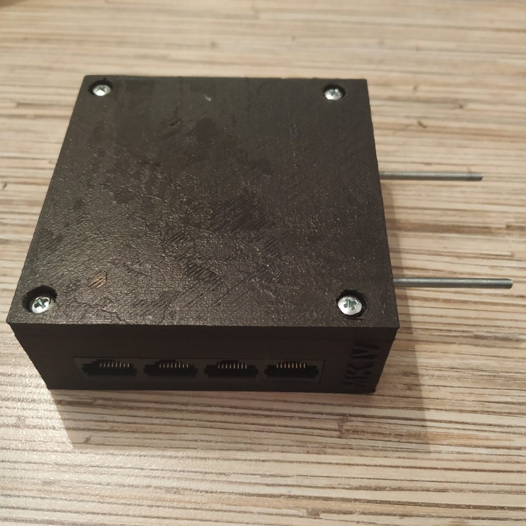
12. Put the lid onto the controller box and fix it with 4 M3x30 screws.
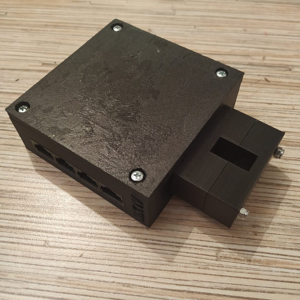
13. Put mounting brackets on and add nyloc nuts. The controller is finished!
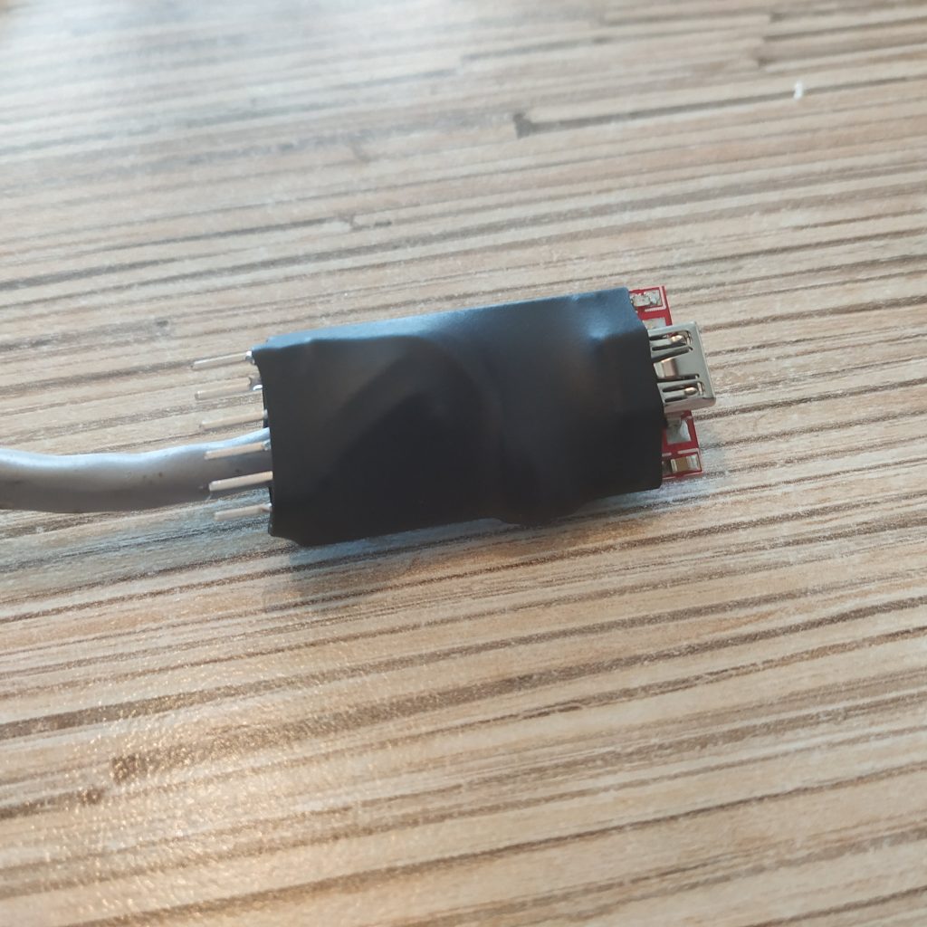
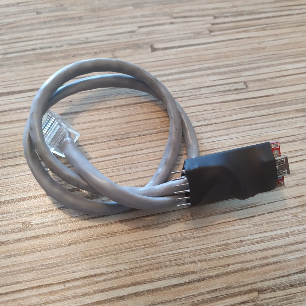
USB – Ethernet cable for flashing peripherals
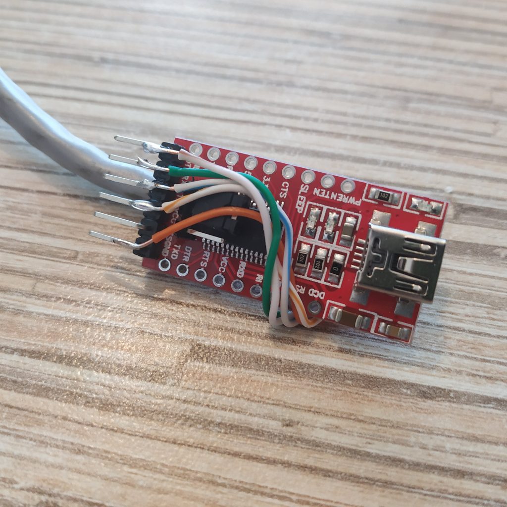
FTDI232 USB-UART board is used to flash most of MKIV peripherals. In fact, you can ofc use any other one, the only thing being if it does not have a DTR pin, you will need to press the reset button on the peripheral manually during flashing.
Note that some devices (like the compact head) still need to be flashed through their UART header, so solder wires to the back part of pins so you can still use jumper wires to connect the header to Pro Mini board.
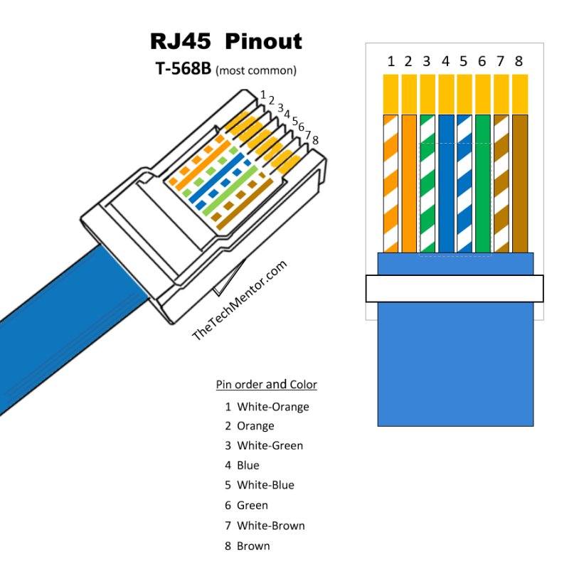
WHITE-ORANGE -> FTDI232 VCC
ORANGE -> FTDI232 GND
WHITE-GREEN -> NC
BLUE -> NC
WHITE-BLUE -> FTDI232 TX
GREEN -> FTDI232 RX
WHITE-BROWN -> FTDI232 DTR
BROWN -> NC
Thanks for upload this manual !!!
You’re welcome! There will be a video about how to use the software soon.
What is the material u use to cover the tie and the FTD board ?
Its called heat shrink tube, you put it on, heat it with a lighter, and it shrinks and becomes quite rigid, good for protection of stuff.
Hi,
Can u pleas explain the need of the FT232TL ?
FTDI232 board is used to flash Arduino Pro Mini boards. Every peripheral has a separate Pro Mini board in it, except for cyclic and pedals, they have 15-bit ADS1115 ADCs onboard.
Thanks,
But as i remember u can flash the Arduino code directly to the board.
Am i wrong?
Pro Mini has no USB interface, thats why you need a USB-UART board to flash it. Leonardo and most of others is flashed through its USB port, yes. In MKIV, Rx,Tx and DTR pins are connected to Ethernet socket, so you can flash the board with a special cable without disassembling anything (well, most of the devices)
What i miss ?
I not see any use in this MKIV tutorial with pro mini.
I really confuse 🥺
Sorry!
My bad
I found that in all the other components (Cyclic, Collective Head, etc..) have a Mini pro board
Not really, in cyclic and pedals, we have a 15-bit ADS1115 analog-to-digital converter board (ADC). It’s connected to the I2C bus just like everything else. Everything else has 1 or more Pro Mini in it =) E.g. MKIII VRMax collective head has 4 of these.
Hello,
First of all congratulation for this fantastic job and thanks very much for sharing it.
i was planning on starting this build with my two sons to teatch them some 3D printing, electronic and hack…….
for the moment, i just started looking fort parts.
i have a quick question about the new master controller (and will certainly have a lot other to come…… 😉 )
when putting the switch on fly mode is the switch open or closed. i understand the wiring but i’m a beginner in arduino and can not find the answer in the code.
thanks very much in advance for your help.
best and once again congratulation.
Pascal
hi! Thanks for your kind words. In the fb_setup_body tab you can find these lines:
pinMode(2, INPUT_PULLUP);
//pinMode(4,INPUT);
//digitalWrite(7,HIGH);
g_operating_mode = !digitalRead(2);
#endif
if (g_operating_mode == 1) {
setup_uart();
} else {
…
that basically means on startup, digital pin 2 is read and if its lit, the board loads in the programmer mode.
Cheers!