Summary
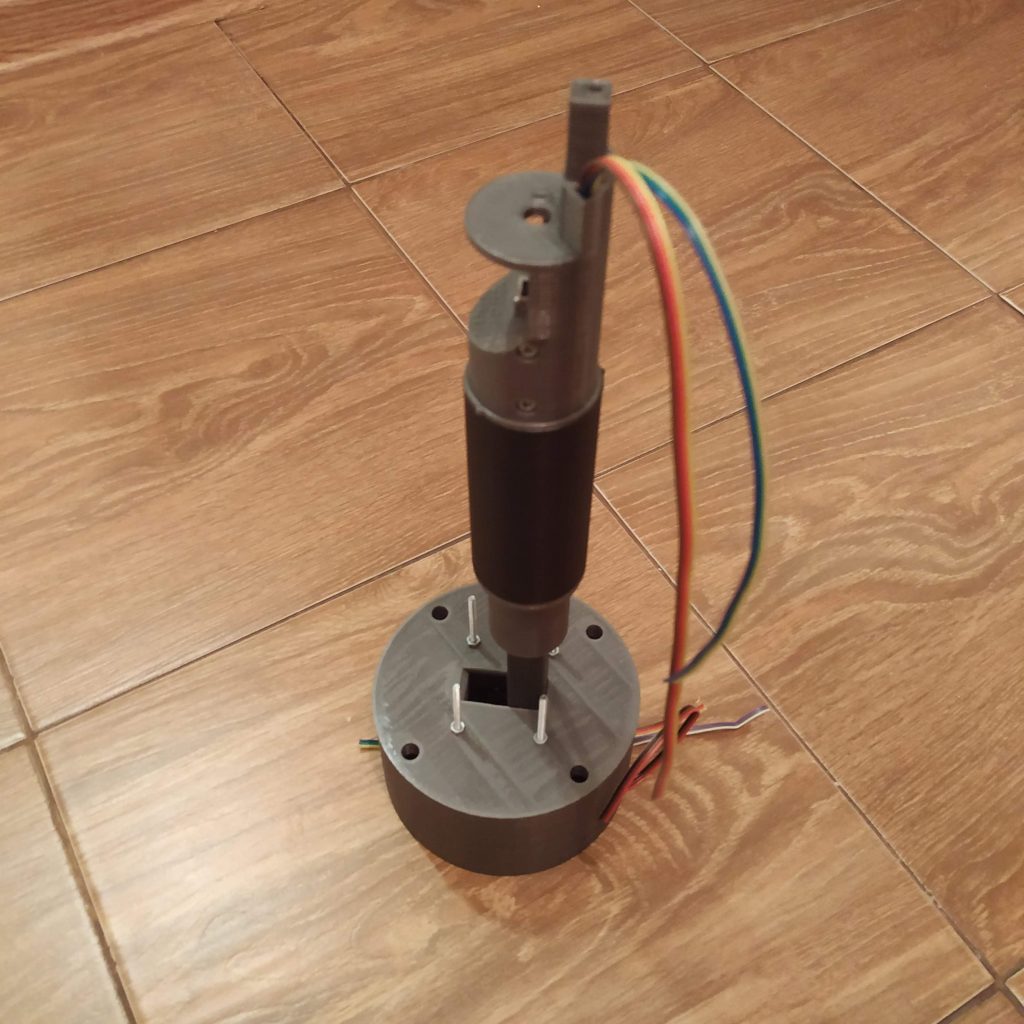
This is a Bell 412-style twin-throttle collective lever. It has a 40mm diameter and 200-degree throttle travel range, just like the real one. The lever works great, supports switchpanels (heads) and feels even better if used with pneumatic mod.
Components
1 * PLA plastic spool
1 * SS495A1 Hall effect sensor
1 * 6x6x4 or 5*5*5mm magnet
2 * 608 bearings
2 * 16K1-B10K rotary pots
8 * M8x75mm bolts
10 * M3x35MM screws
3 * M3x20mm screws
8 * M3x40mm screws
1 * bag of M3 nuts (at least 41pcs needed)
4 * M3 nyloc nuts
1 * 10x10x1000mm aluminum square tubing
1 * ethernet plug
1 * Arduino Pro Mini
1 * Simchair MKIII master controller (1 is needed for the whole set)
Available mods
- 5x5x5mm magnet holder
- pneumatic mod
Special features
- aircraft compativility modes support
- collective hold support
Downloads
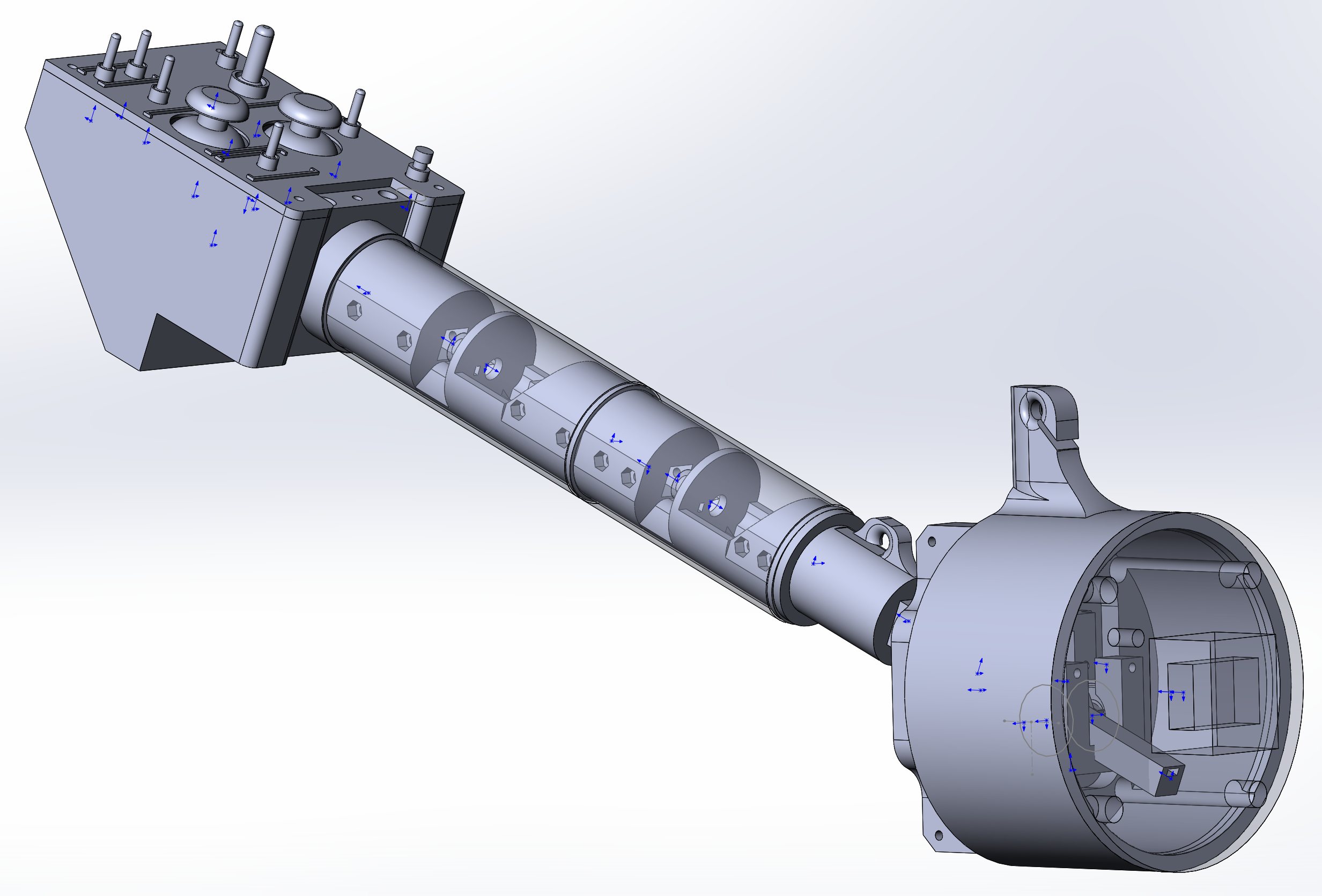
Assembly
Please carefully follow the steps of this manual! It will save you a lot of time and nerves.
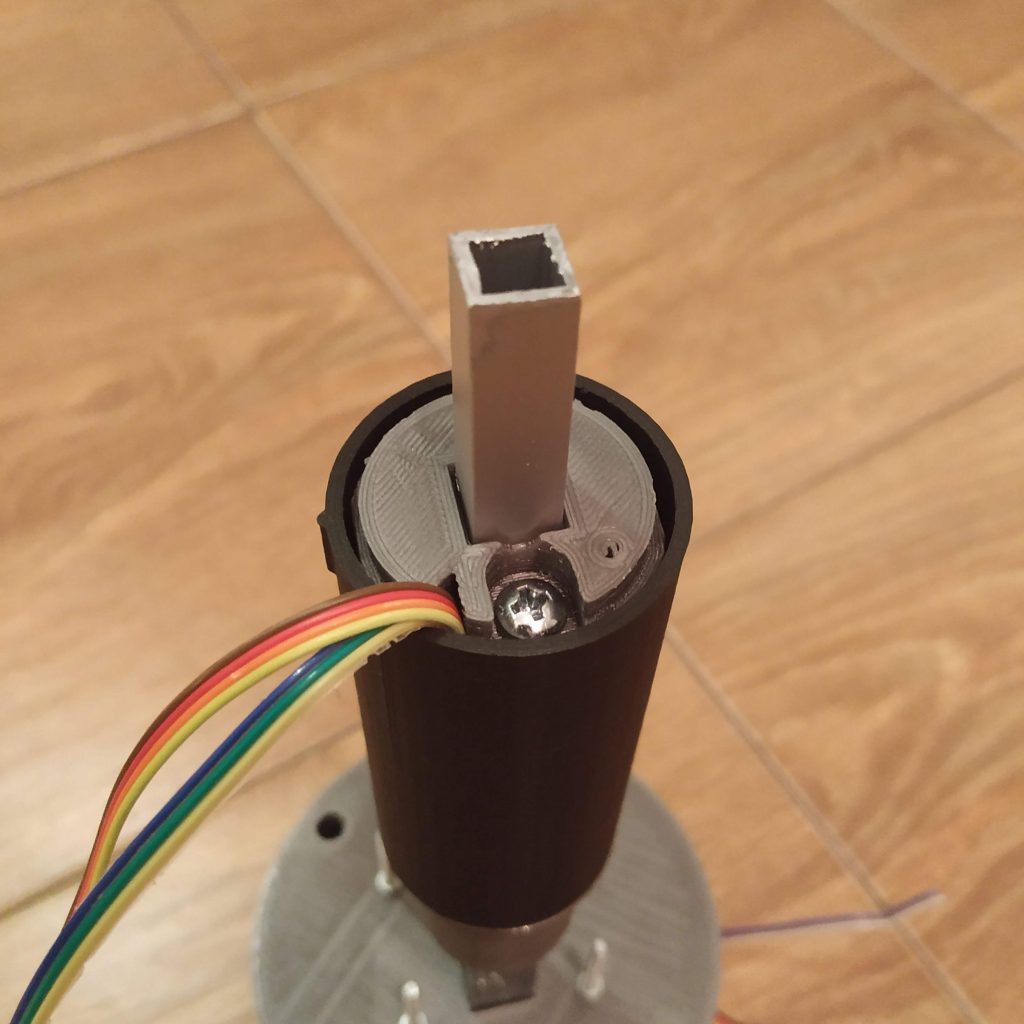
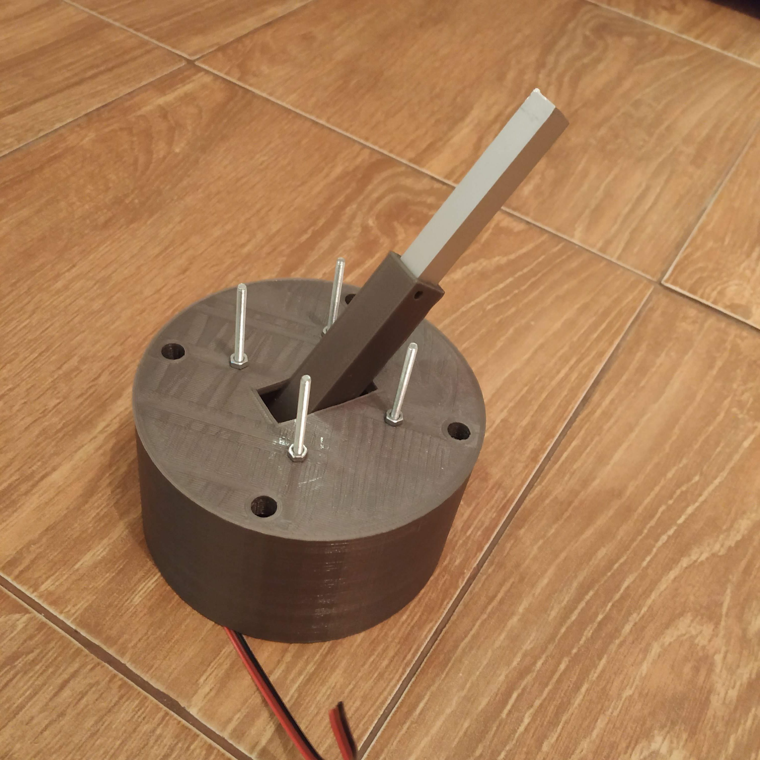
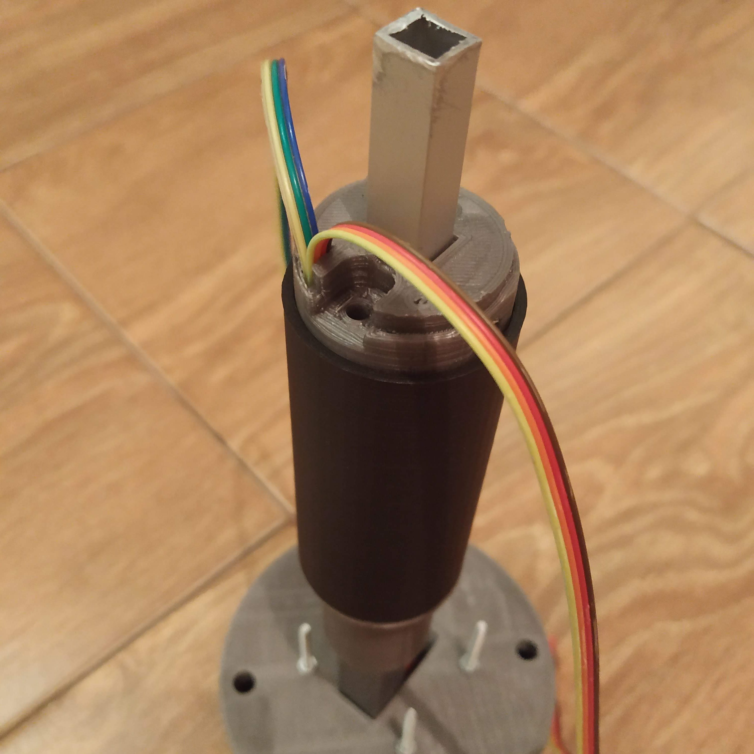
- Attach a piece of aluminum square pipe to the lever connector part. Cut the pipe so it will not protrude from the throttle frame p2 part when attached.
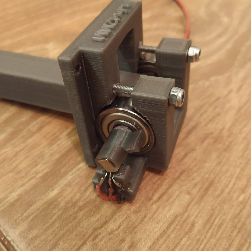
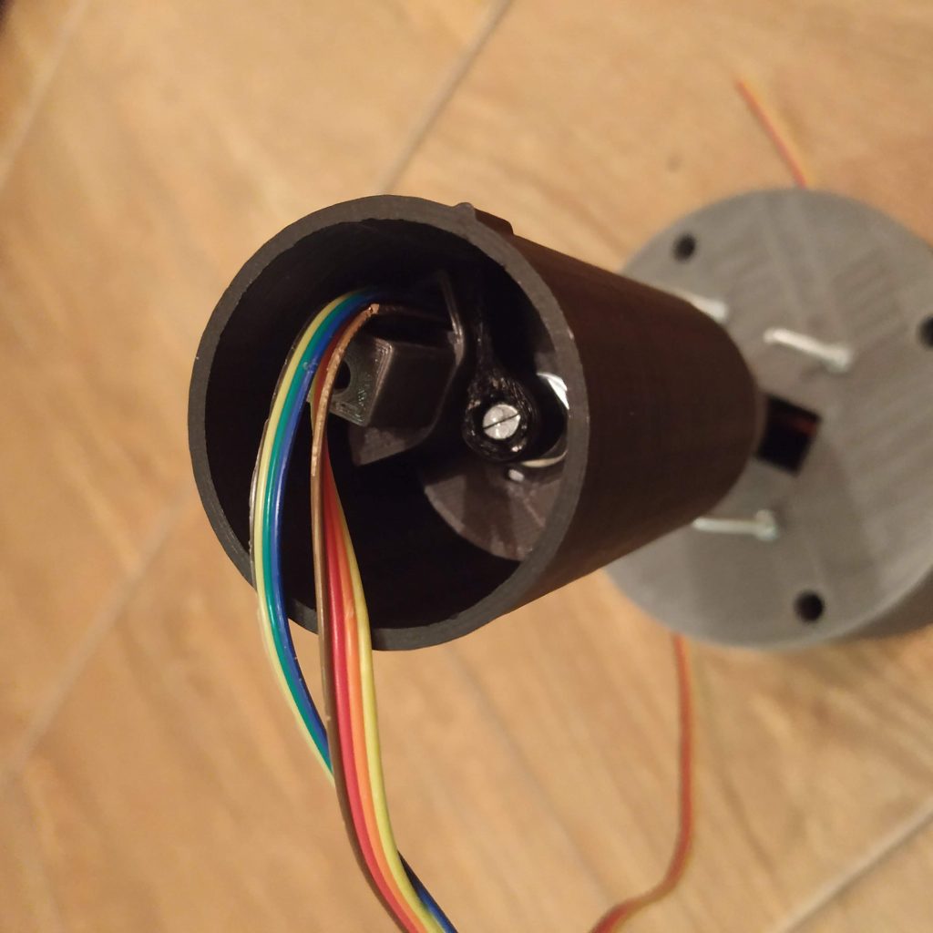
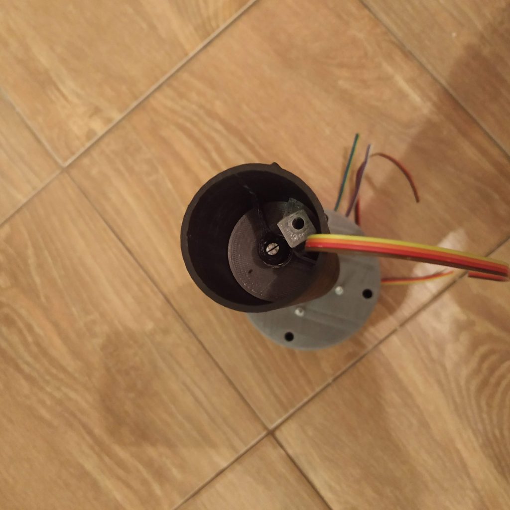
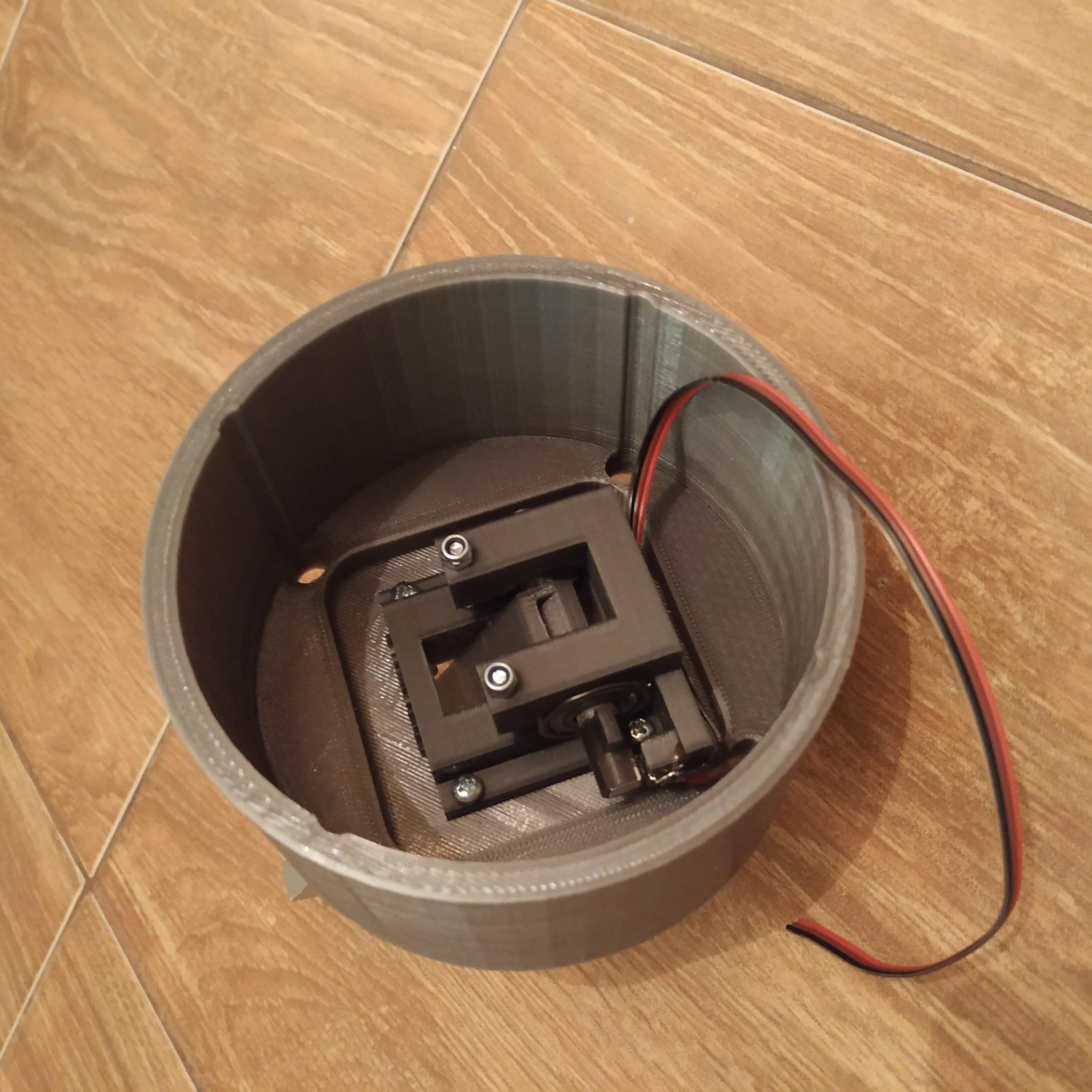
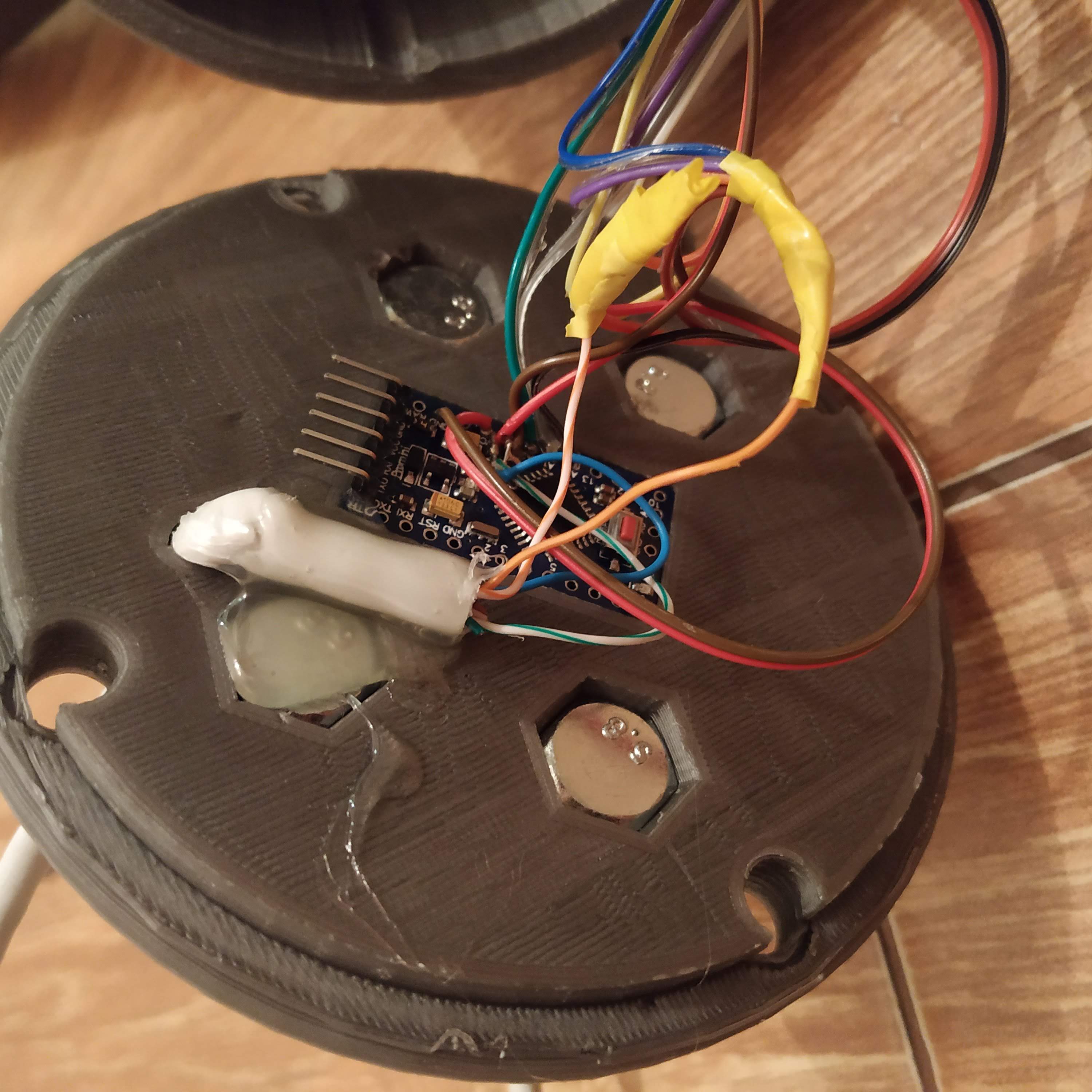
- Insert SS495A into its socket, secure with cyanoacrylate. Wait for it to dry and solder its wires. Glue wires to the bottom of the frame with hot glue.
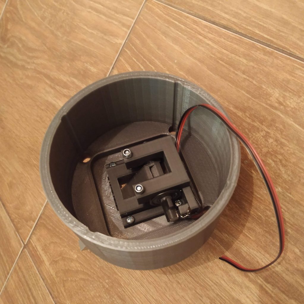
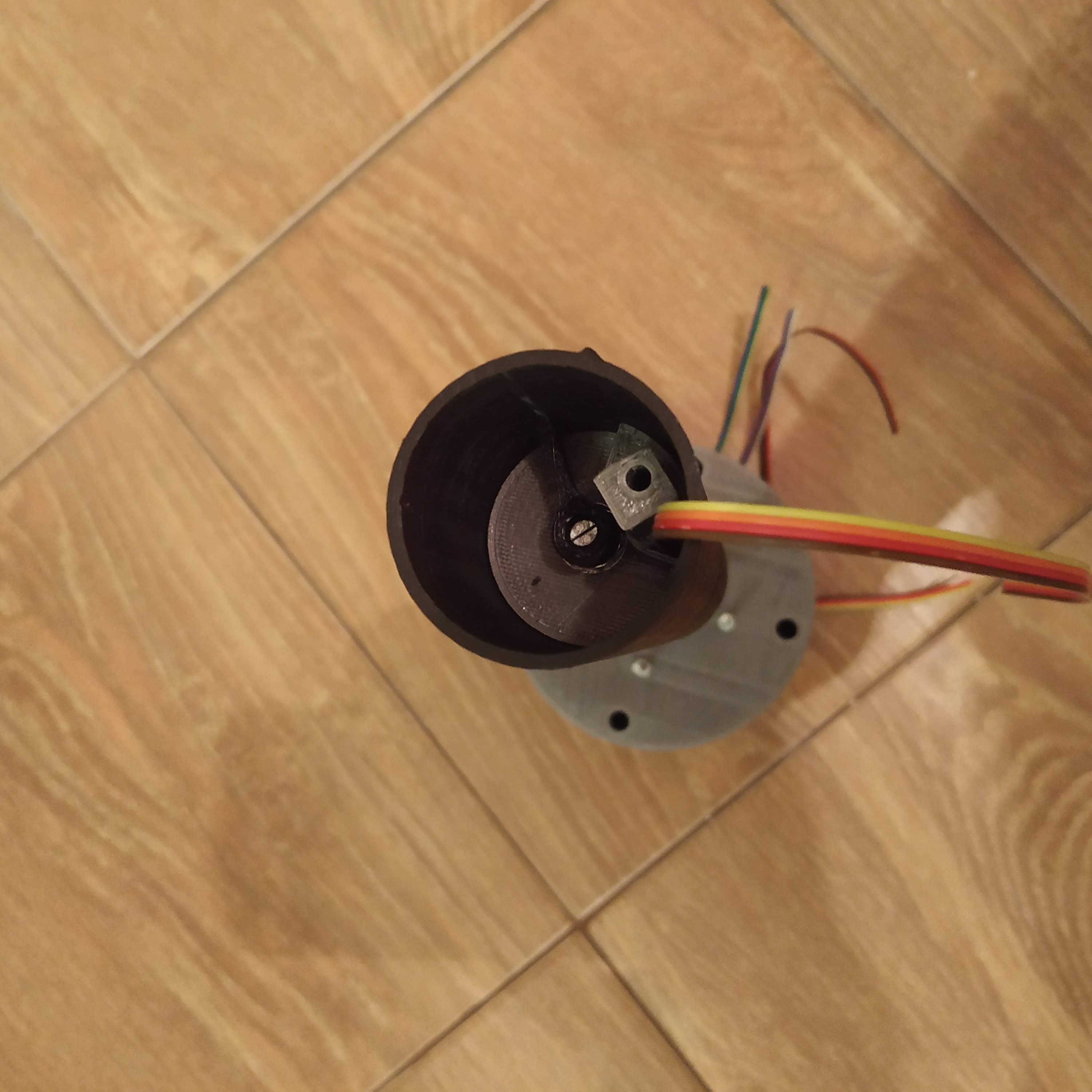
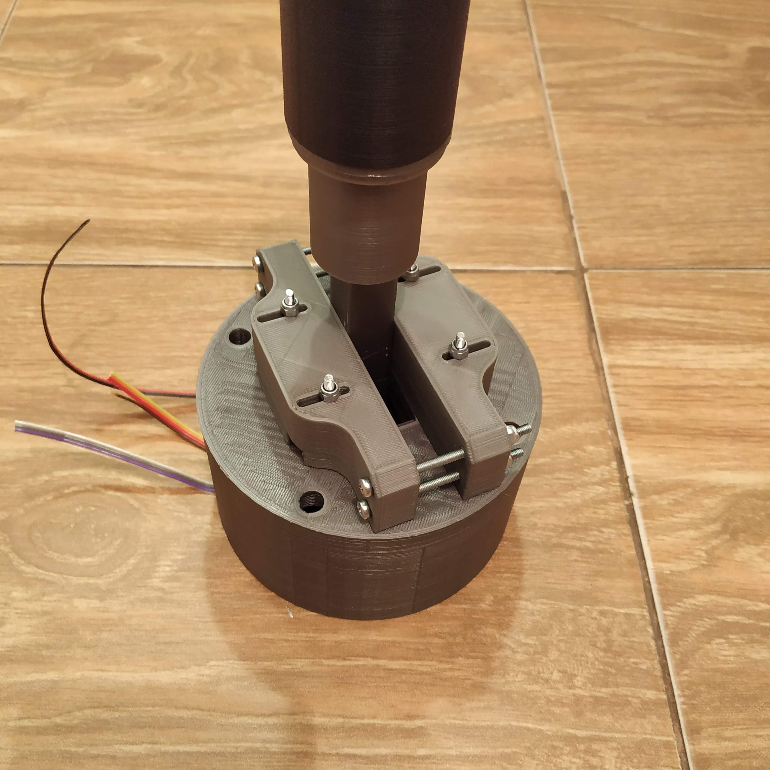
- Insert lever connector to its frame (cable channel slot must be on the top), press-fit bearings to their sockets.
- Insert two screws into the lever frame part. Do not overtighten.
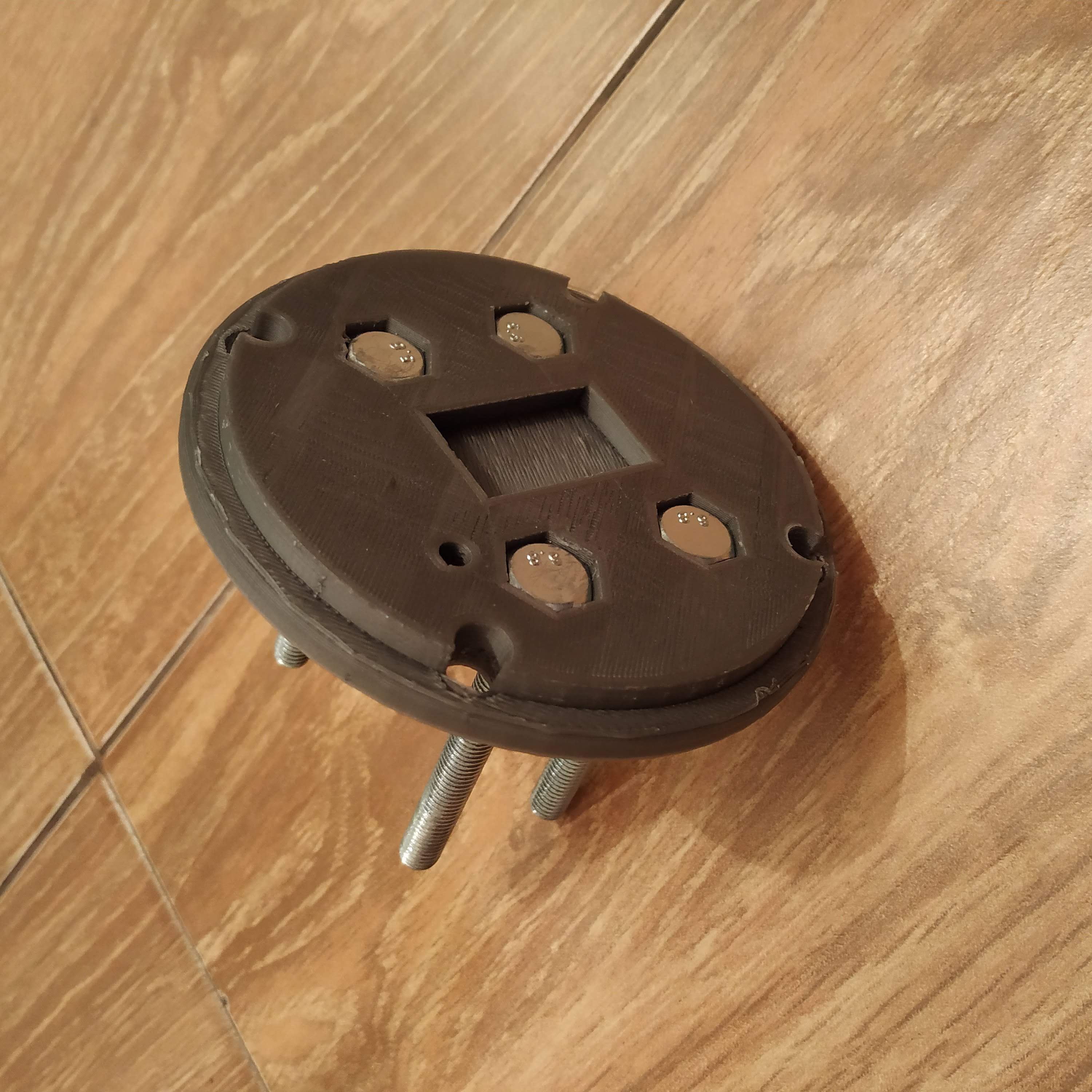
- Attach the magnet holder part with 20mm screw, insert magnet into it.
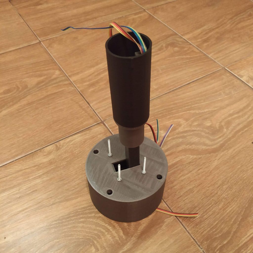
- Insert lever frame with the lever connector attached to the enclosure part 1, secure it with M3x40 screws, put nuts on the screws, tighten them. Gimbal assembly is now finished.

- Attach pot to the throttle 2 frame part 1
- Press fit M4 nyloc nut to the throttle 2 frame p1
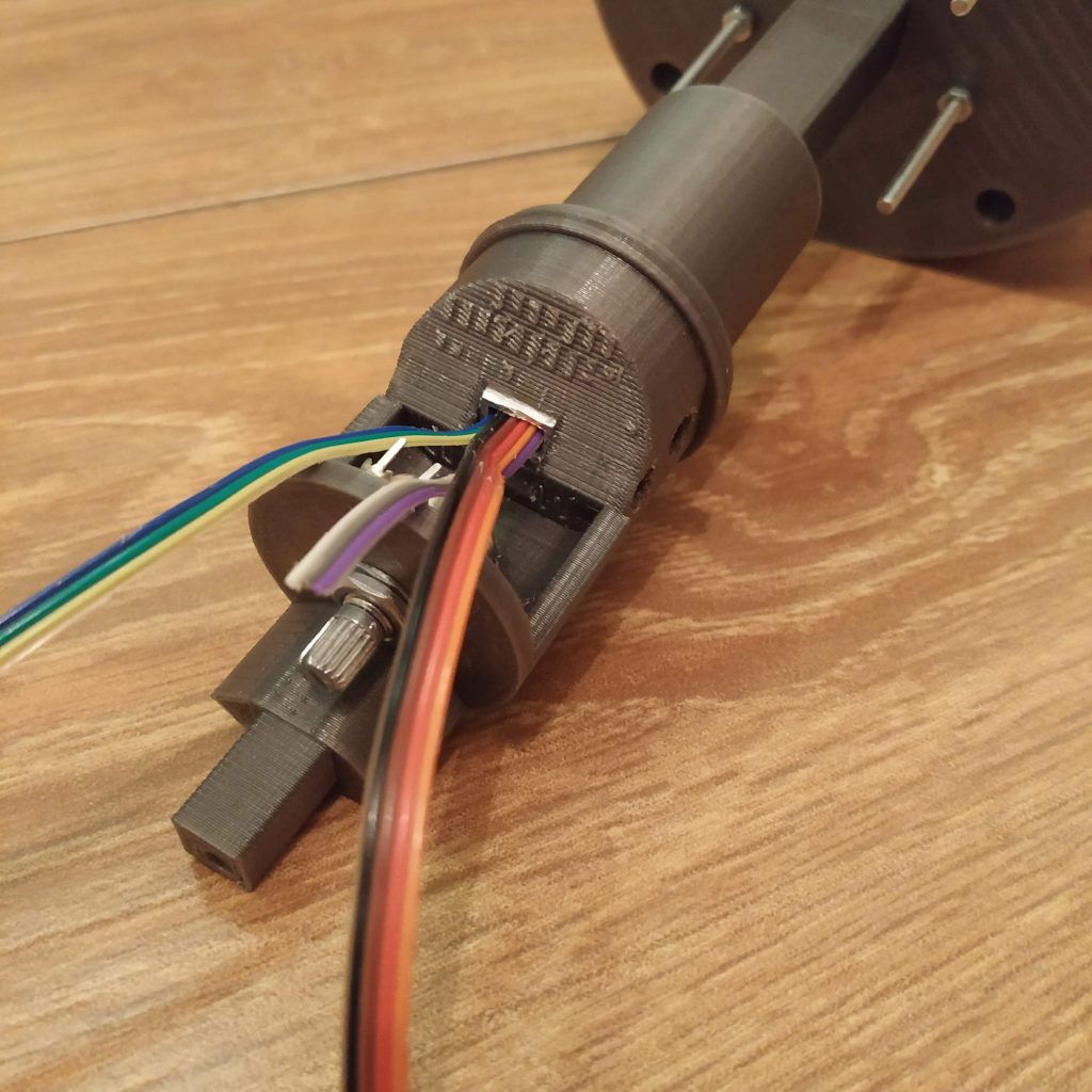
- Attach rubber bands holder to the lever connector (press fit onto the alu pipe)
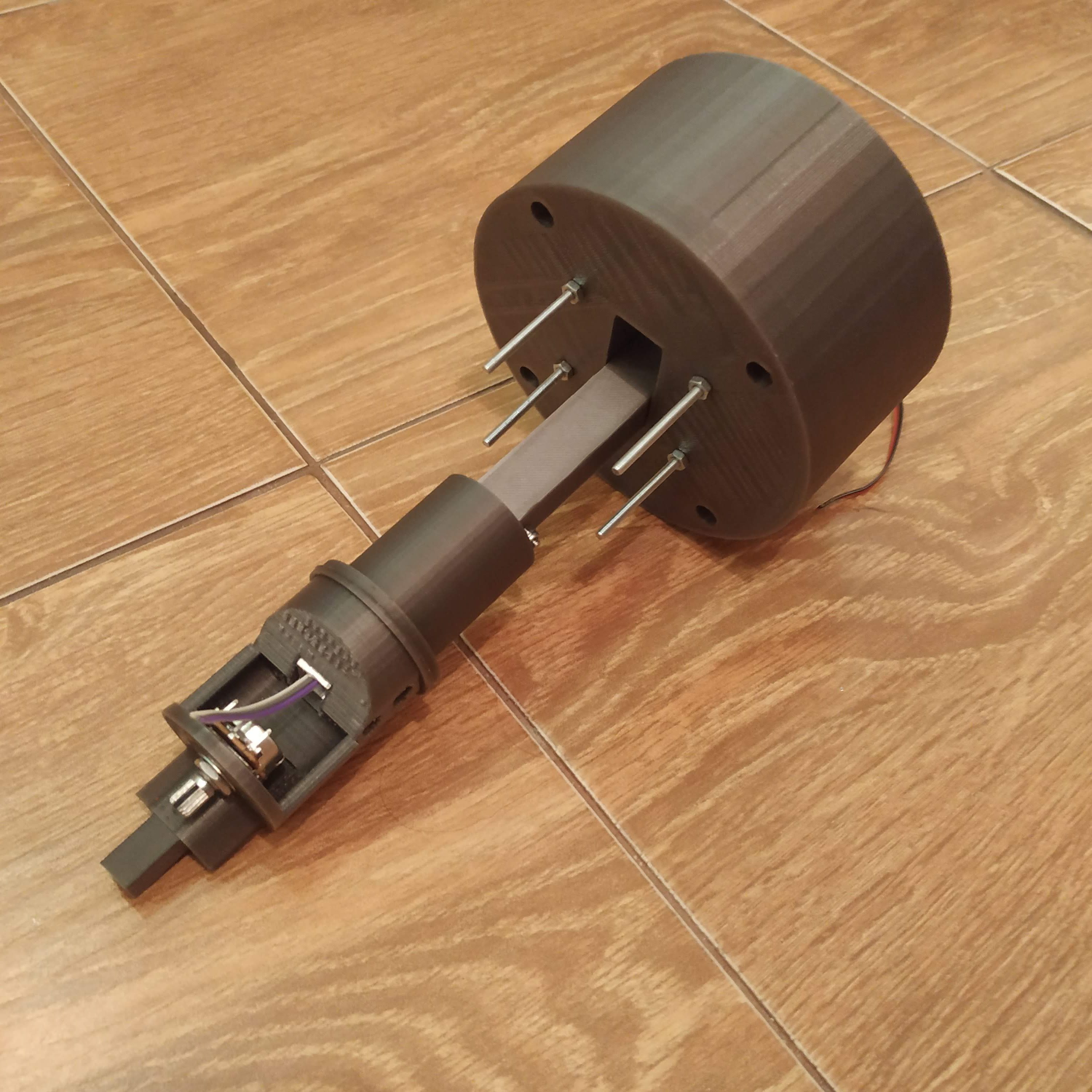
- Attach throttle 2 frame p1 to the lever connector (press fit onto the alu pipe); disregard the cable on the next picture – only insert cables after holes in these parts are drilled and screws are tightened!

- DRILL HOLES IN THROTTLE 2 P1 AND LEVER CONNECTOR; INSERT AND TIGHTEN BOLTS; NEVER TOUCH THEM AGAIN!
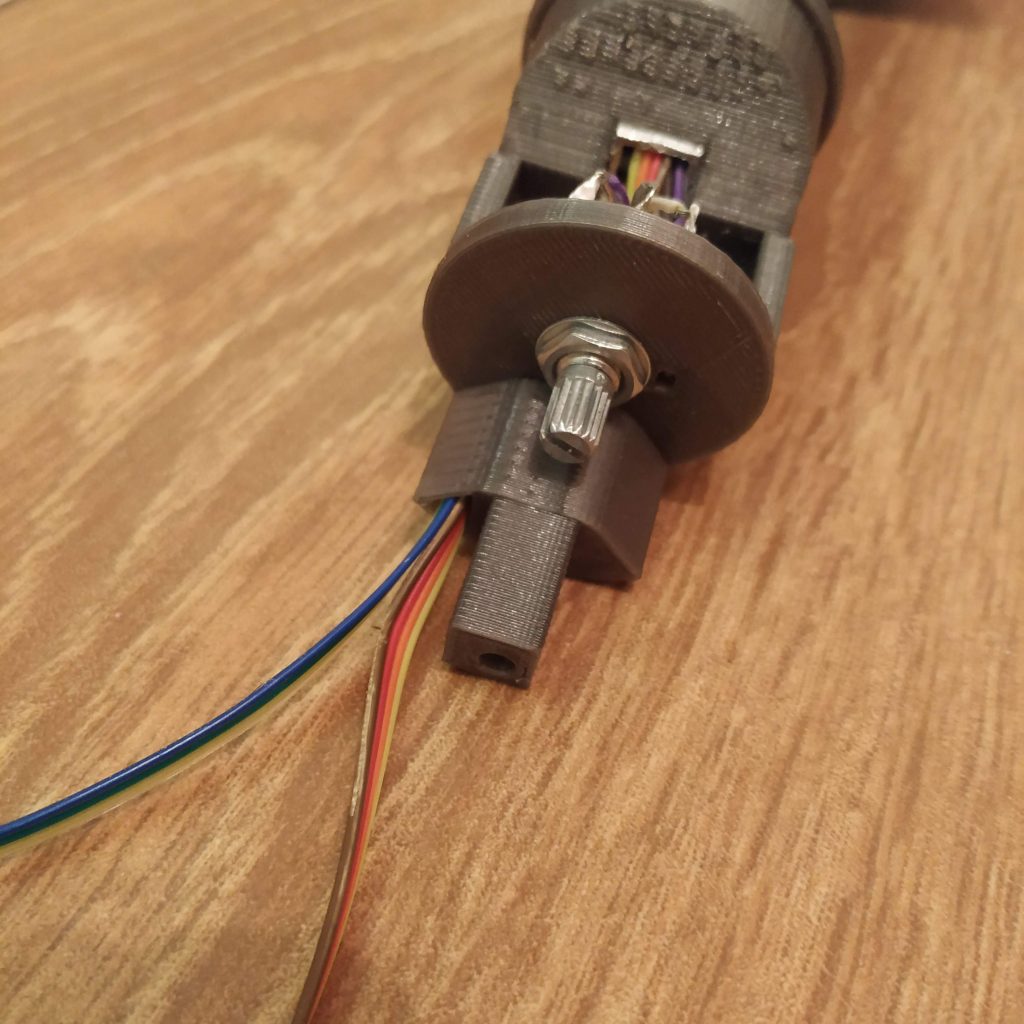
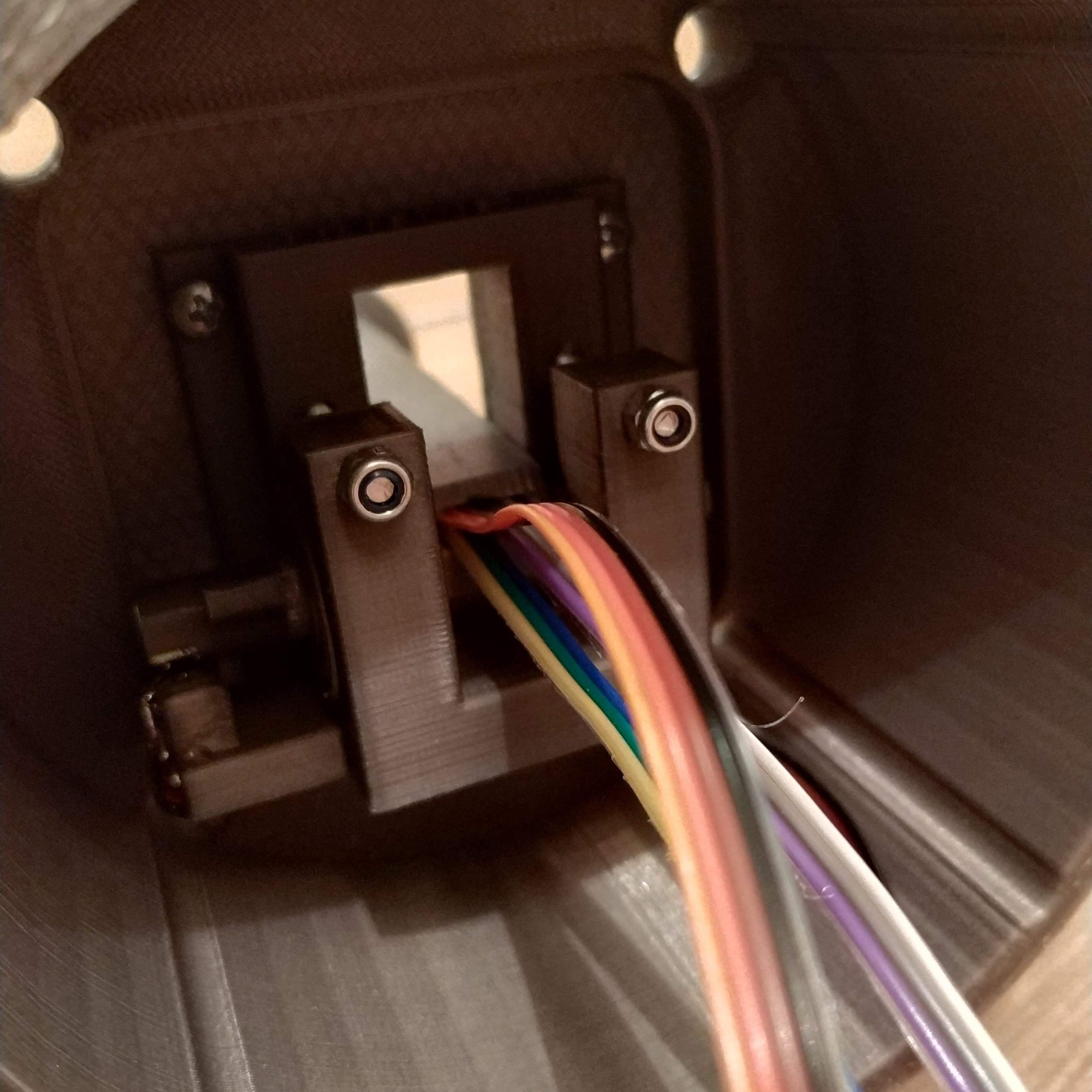
- Route two throttle pot 3-wire ribbon cables and one 4-wire I2C bus cable through the lever, solder throttle 2 pot

- Route first throttle pot and I2C bus ribbon cables through the cable channel in throttle 2 frame
- DO NOT TOUCH THROTTLE 2 P1 SCREWS AND LEVER CONNECTOR SCREW WITH WIRES INSIDE OF THE LEVER! YOU WILL TEAR WIRES APART (I WARNED YOU!)
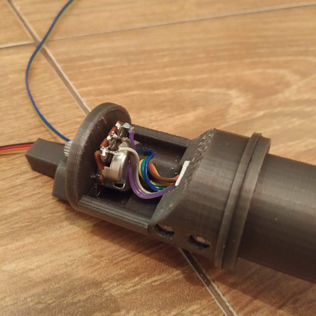
- Turn the throttle pot fully to the left (relative to the normal collective position in a helicopter – throttle should be fully opened), then just a bit to the right (it has a mechanical deadzone at its ends) and attach throttle 2 grip (carefully push its inner connector onto the pot with a screwdriver of pliers, squeeze the pot knob if needed
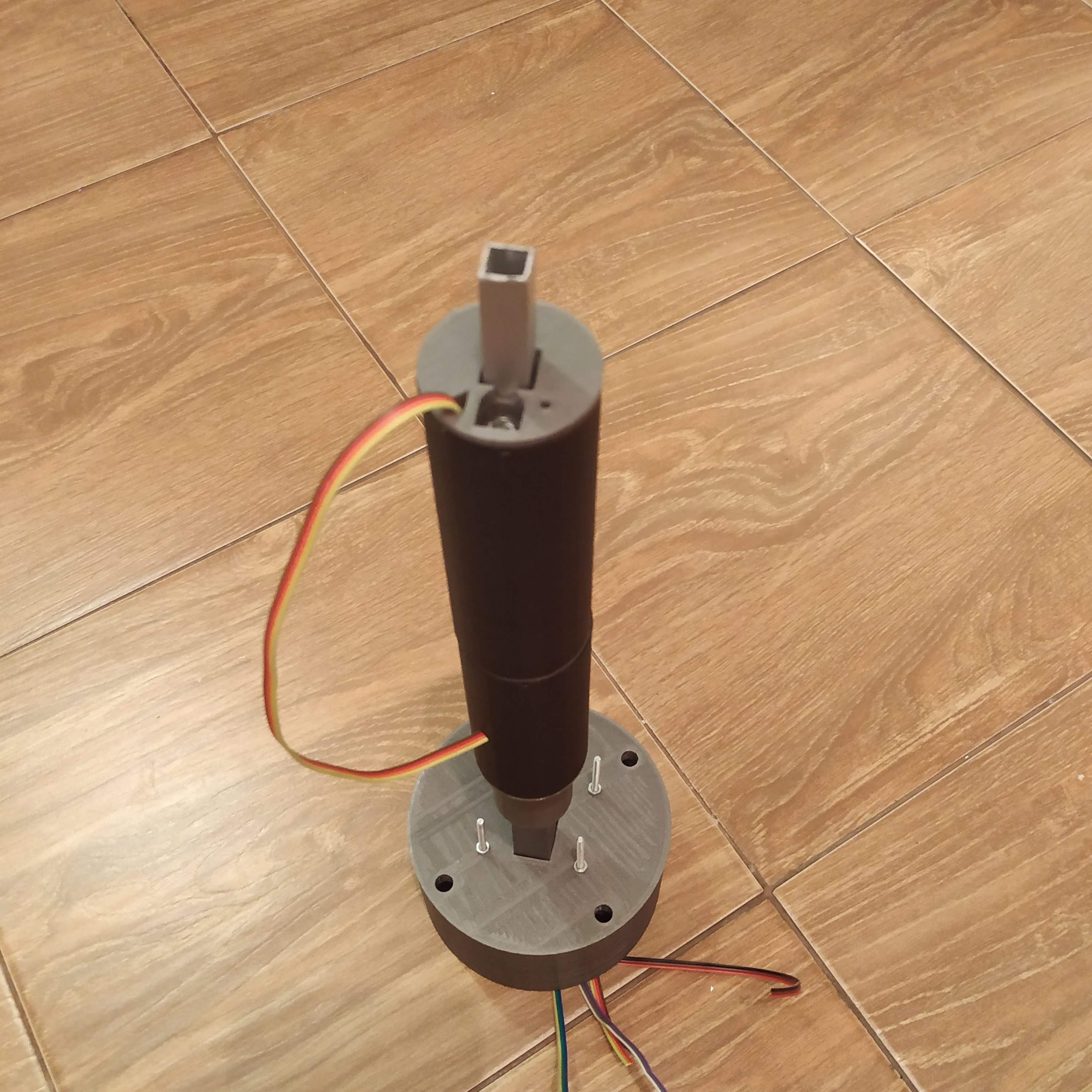
- Insert a piece of alu pipe into throttle 2 p2; drill holes and insert screws.
- Route wires through cable channel and press fit throttle2 p2 onto throttle 2 p1

- Tighten throttle frame parts together with m4x80mm screw, choose a straight one
- Press-fit m4 nyloc nut to throttle 1 p1
- Route cables through and attach throttle 1 p1
- Drill holes, insert screws into throttle 1 p1
- Pull throttle 1 pot wire out of the cable channel and solder it to the throttle 1 pot
- Attach trottle 1 grip
- Insert alu pipe into throttle 1 p2; drill holes and insert screws
- Pull I2C ribbon cable through throttle 1 p2 and attach throttle 1 p2
- Insert an M4x80mm screw

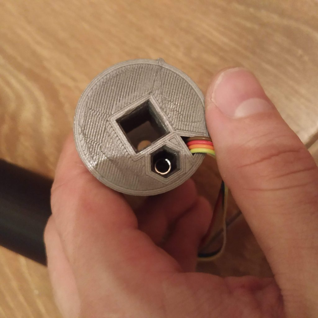
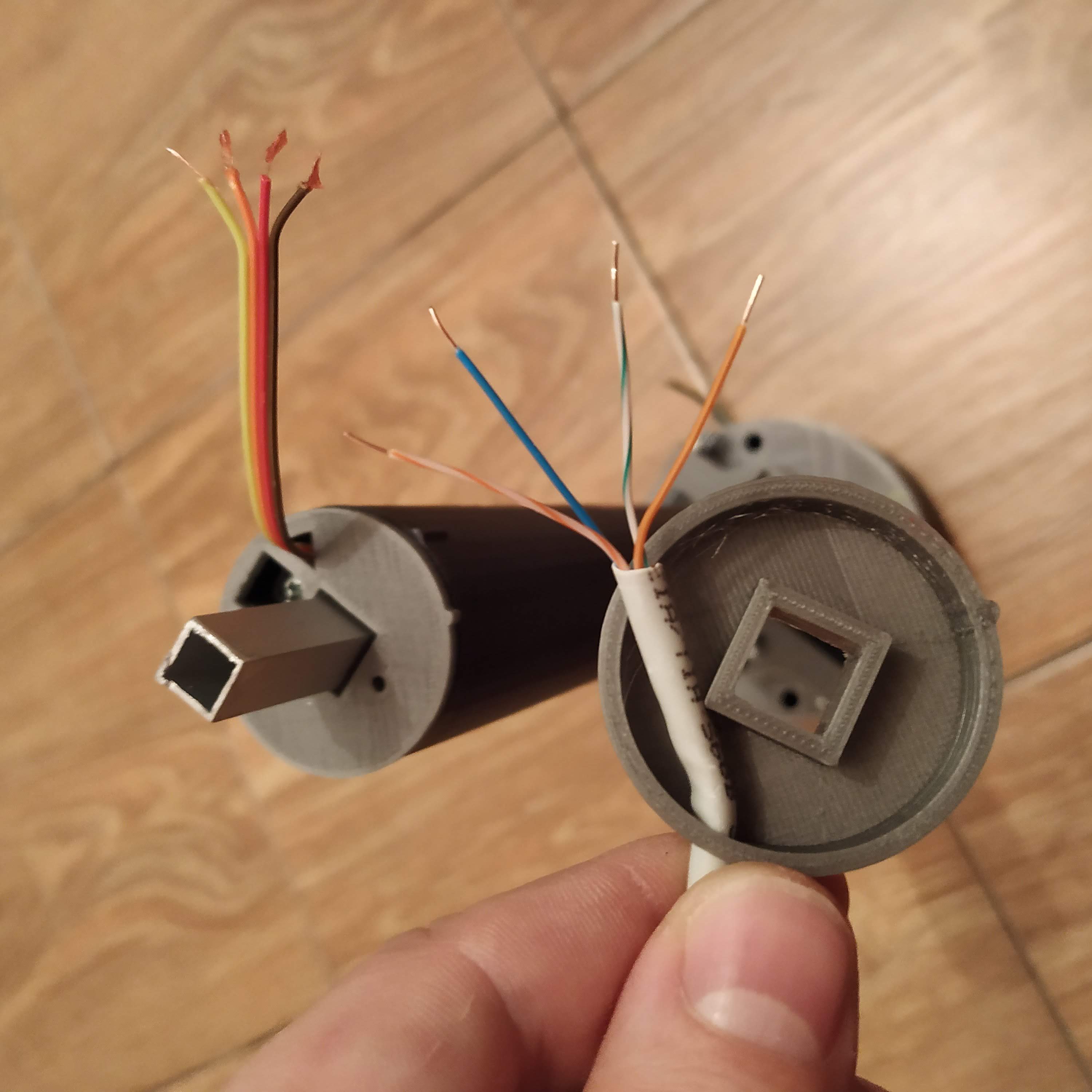
- Pull a piece of ethernet cable through the I2C connector part, cut and solder I2C ribbon cable wires to it

- Crimp the ethernet cable as usual (as per T568B standard)
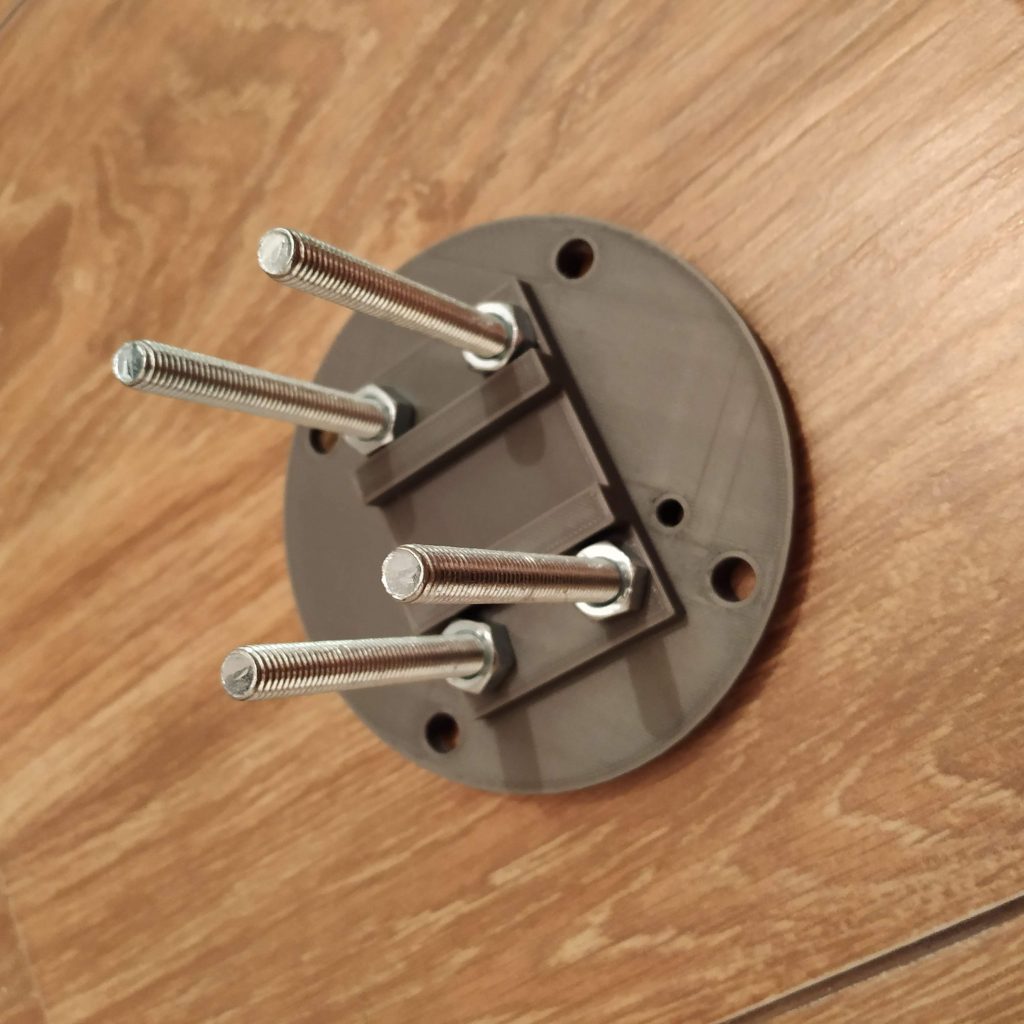
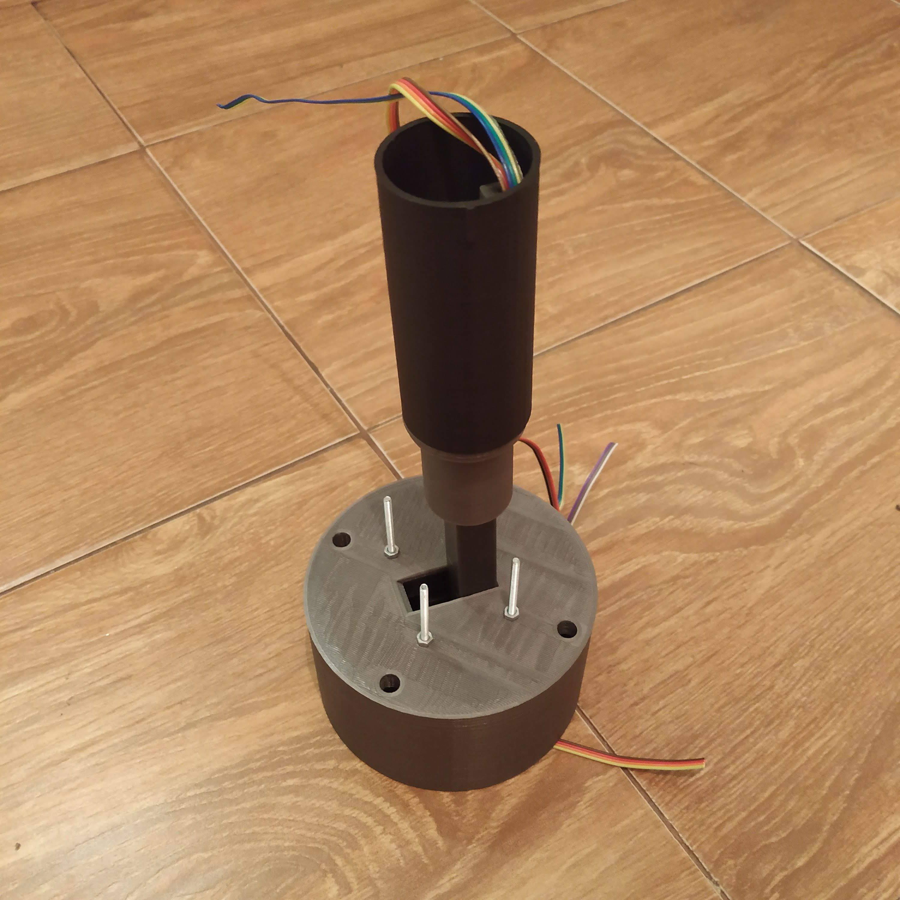
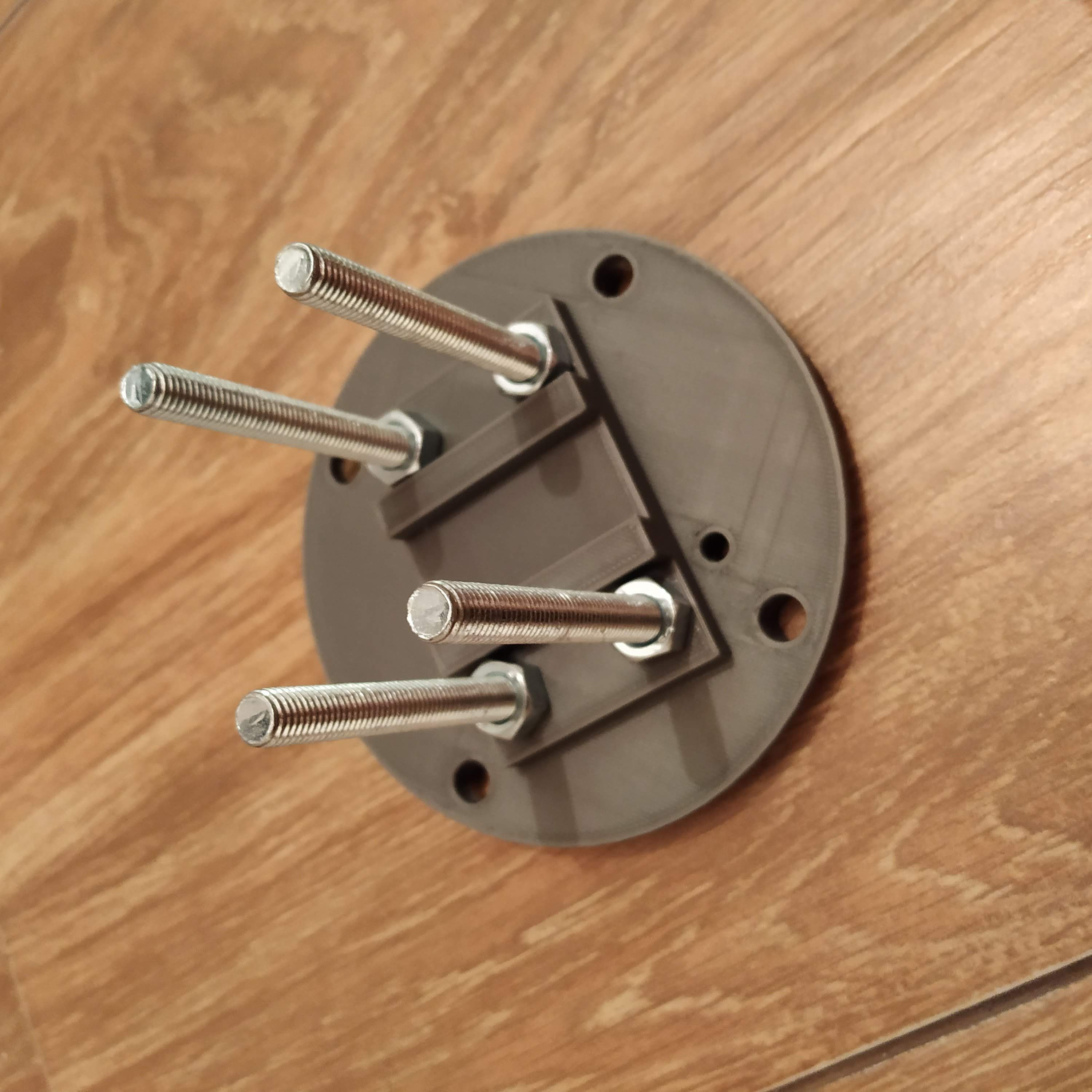
- Attach tensioner halves and secure them with nuts, insert 4 M3x50mm screws into halves.

- Put bolts through the bottom lid of the enclosure, fix wih nuts

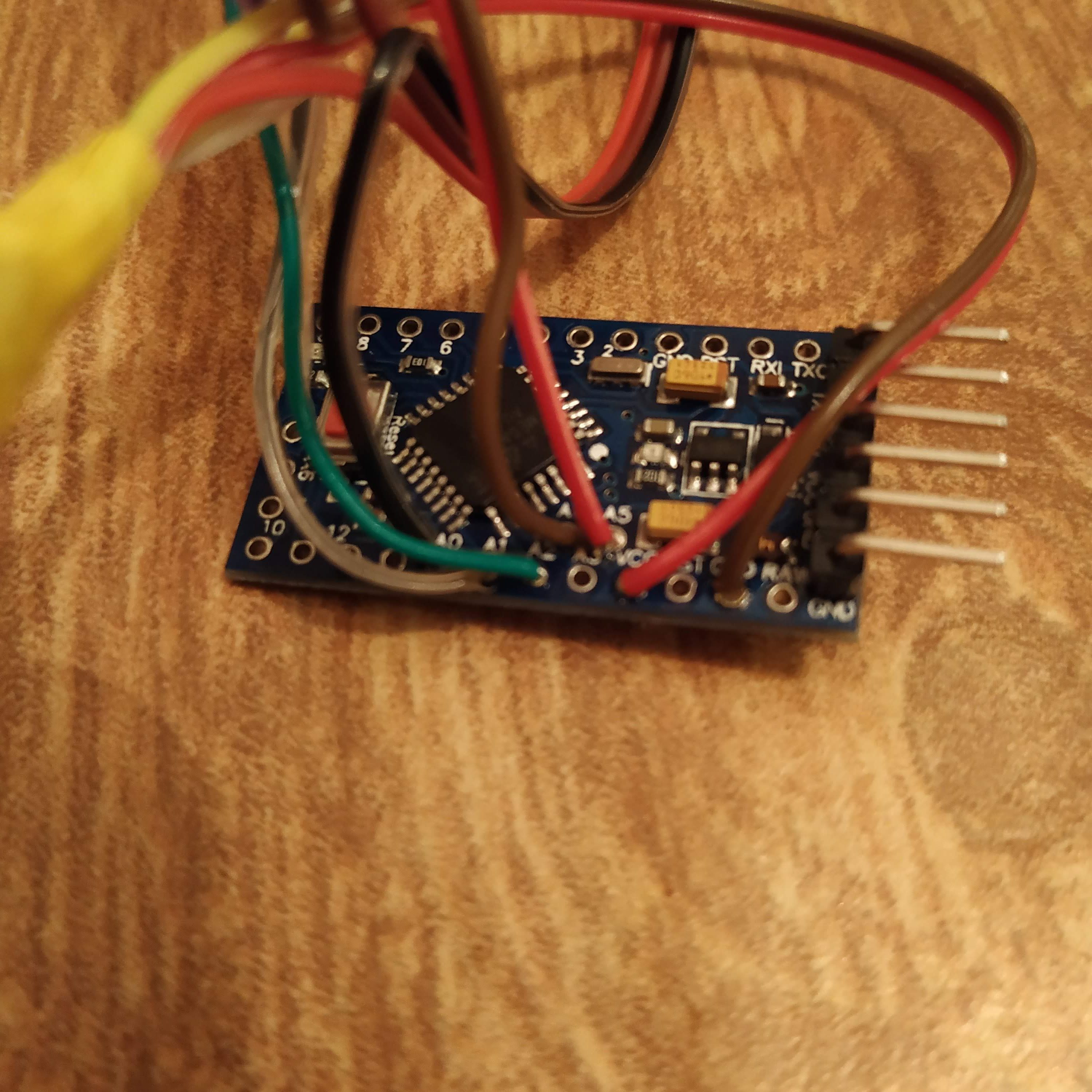
- Solder pin headers to an Arduino Pro Mini so they would face up (not down as they are facing normally)

- Solder all 5V and GND wires together correspondingly
- Route ethernet cable through a hole in the bottom lid of the enclosure and solder white orange wire to 5V, orange to GND, white-green to SCL and blue to SDA wires, then solder everything to corresponding pins of the Arduino

- Solder SS495A signal wire to A0, throttle 2 pot signal wire to A1, throttle 1 signal wire to A2
- Connect arduino to the programmer; open the firmware
- Comment “map” lines and uncomment Serial.prints in firmware file
- Flash the firmware
- Check numbers react to lever movements
- Adjust magnet holder position for max collective lever range
- Enter min and max values to corresponding map functions; uncomment maps and reflash the firmware
- Check all axes are in range 0 -1023; if not, adjust map functions values again
- Comment Serial.prints and reflash firmware
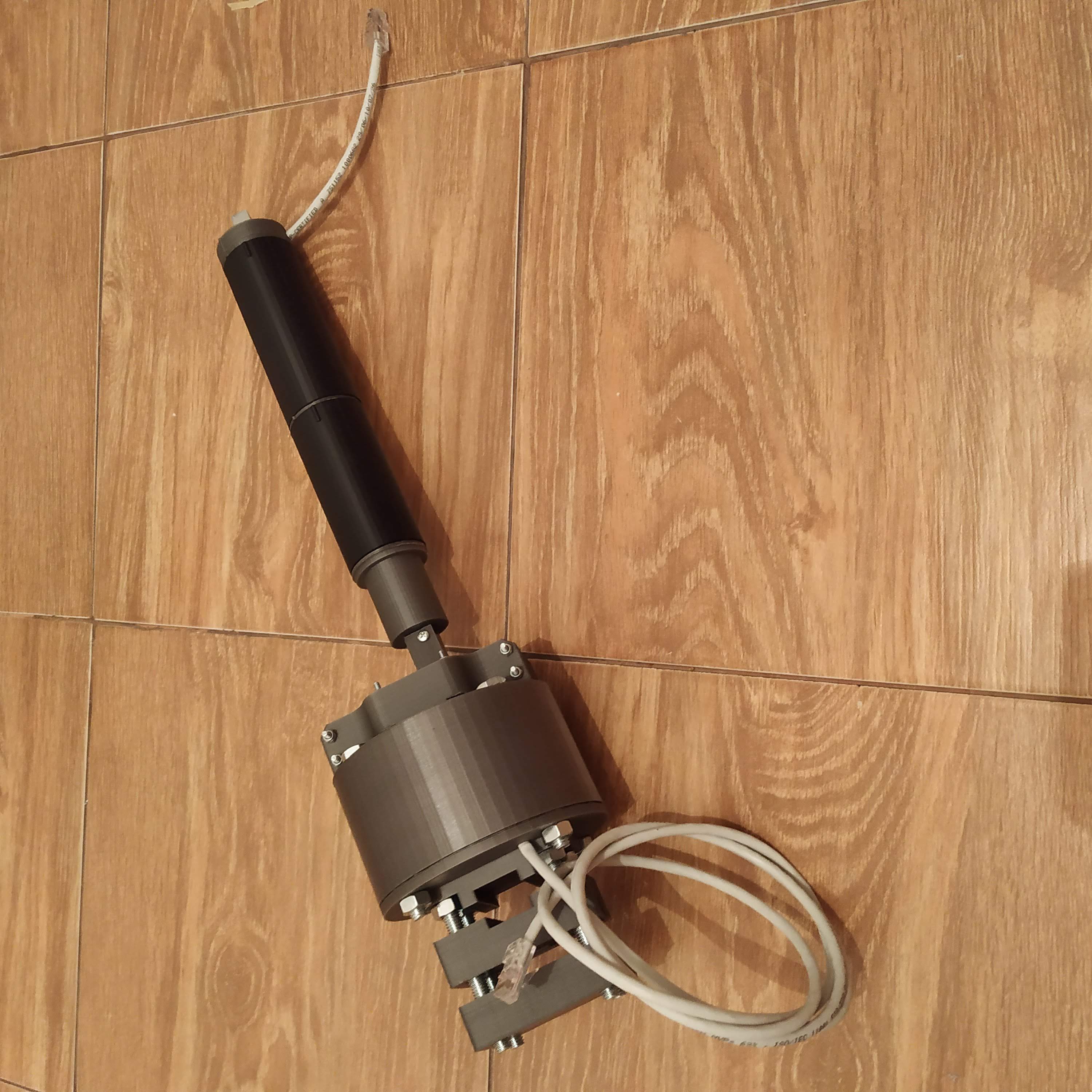
- Crimp ethernet cables and plug the lever into the master controller
- Check axes move as intended (collective up – axis up, throttle left – axis up) in joy.cpl, invert in firmware (swap 2 last numbers in map function) if necessary
- Secure arduino in its socket with a piece of 2 sided tape, glue wires with hot glue
- Check everything again. Congratulations! You are ready to fly with your new collective lever!


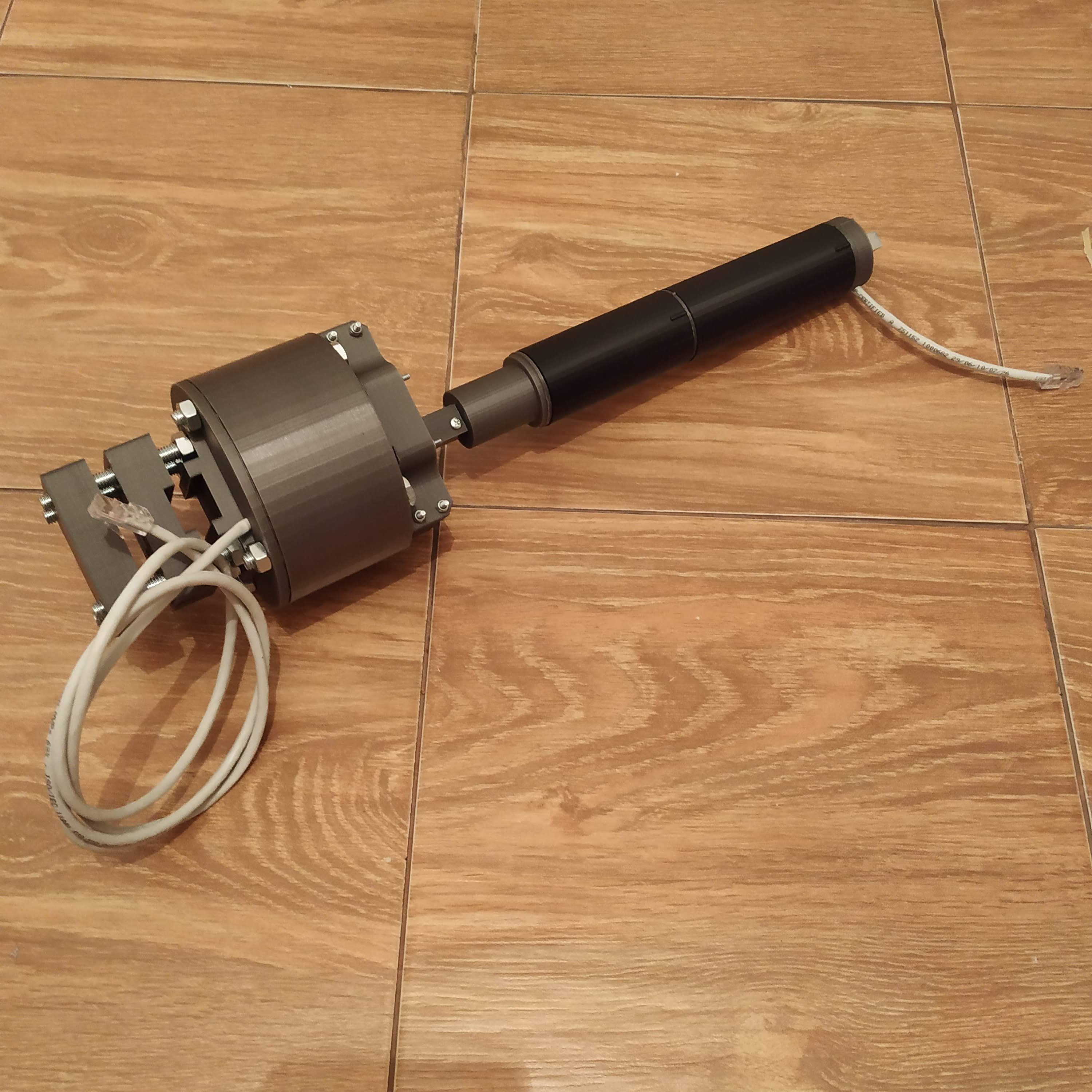
Here’s what it should look like at this point (I have used some parts from the pneumatic mod in this build):
Now, it’s time to choose which switchpanel you will be using, for now it’s either Huey head or Bell 412 head.
Also, I strongly recommend you to have a look at the pneumatic mod, I really can’t imagine flying without it now.
Hi Alex,
how do I contact you? (Email?)
I’d like to ask about extending the firmware so I can build an AS250 stick which has a lot of buttons etc.
Thanks
Matt
Hi Matt! No problem with extending firmware, we will figure something out =) Would be also great if you share the design of the stick grip with the community!
Hello hc625ma,
I follow your projects with great interest – amazing staff!! Actually I am printing your reinforced cyclic gimbal, but as I have to use 5x5x5mm magnets I cannot use your magnet holders . Is it possible for you to provide a magnet holder for those smaller magnets as well? I would do it by myself but unfortunately I don´t have SolidWorks.
Many thanks in advance!
Guido
Hi Guido! Thanks for your kind words!
I will publish a mod for you in a couple of hours, however, won’t be able to try it myself, so please tell me how it worked for you =)
Cheers!
Btw, I have not published assembly manual yet, so please look at the assembly using some viewing software: (I think eDrawings can open these files). Now when I know you’re building it, I will hurry with a manual =)
Here are the holders, try them and please tell which version has worked for you better =)
https://goo.gl/F64USw
Hi Alex – version “a” has not sufficient clearance, we need at least version “b” . Due to printing tolerances I would recommend to add another 0,2mm clearance to version “b” – this would be perfect!
Many thx for your extrem fast response!
Guido
Btw: When will be the assembly manual ready?
Okay, the “A” version is now what has been the “B” one, and the “B” one has 0,2mm increased clearance =) Try it. I hope to finish the manual as fast as possible, maybe today in the evening =) You’ll need M8 hardware, bolts, nuts, spring washers, and strengthened washers, and a lot of M4x40mm screws and nuts.
http://hc625ma.org/wp-content/uploads/2018/10/exploded_view_2.png
http://hc625ma.org/wp-content/uploads/2018/10/exploded_view_1.png
This pictures should give you a basic idea of how to assemble stuff meanwhile =)
Two most important bolts are those that hold magnets, Y one is 30mm, an X one is 55mm (you can cut it from a longer one). You have to add washers (spring washers are fine) between bearings and plastic parts. Make sure everything fits tightly, adjust nuts if necessary.
Please let me know if you encounter some problems =)
Hi HC625ma,
Im having trouble finding the SS495a1 hall effect sensor in Australia.
Will this one work?
https://core-electronics.com.au/a3213-hall-effect-sensor.html
Hi Rowan! Can’t say for sure. It looks like it will fit the socket, but I can’t say anything about its precision or whether the distance between a magnet and a sensor will be appropriate.
However, you can use a regular SS495A (not A1) without any noticeable difference. Can’t say for sure, but it looks like they are available in AU:
https://au.mouser.com/ProductDetail/Honeywell/SS495A?qs=%2ffq2y7sSKcKEzWT94S3drA==
If you decide to use an A3213, please let me know how it worked!
Cheers, Alex
Hi Alex – today first check of controls in x-plane 11. Cyclic and rudders behave as expected, but collective is a bit pumping (oscillating up and down a bit). Is in the firmware a filter or parameter to influence that?
Cheers, Guido
Hi Guido!
There’s an option in i2c_single_engine_collective.ino, you can safely adjust this value.
uint8_t filter_counter_z = 6;
uint8_t filter_counter_rz = 6;
I can also add filtering support to the master controller sketch, but I don’t recommend using it for two reasons:
1) collective input affects the attitude of a helicopter, noisy collective will cause instability.
2) filtering will induce additional input lag.
I am pretty sure this issue can be resolved mechanically, please check if the magnet sits firmly in its socket! If you used 5x5x5 magnet, maybe we need to design a better magnet holder? I would have checked connections as well. How much does it fluctuate? At what position?
Looking at your issue I will be adding a modified housing with a revision hatch for easier access to the magnet tomorrow! If you decide to disassemble stuff, consider printing it!
Hi Alex – after checking all connections, I found out, that at the current status of my built the 2 throttle pots haven´t be connected resulting in that high oszillations in collective movement. With the 2 pots installed everything is fine.
By the way: Why you don´t use for the collective the ADS1115 for higher resolution? It has 4 available adresses so it should work as well!
Cheers and happy flying!
Guido
Glad to hear you’ve sorted this out! As you have said, it only has 4 available addresses – 4 for the whole set. I thought that 1024 points are good enough for the collective – never had a feeling that we need more when flying =)
But you can use it if you want to, should only require minimal changes to the code.
Cheers!
I’ve just finished my twin collective (minus switch head) and gave it a try in XPlane in the 412. I have a really large dead zone on the bottom of the collective. When I have the pro mini hooked up to the programmer and reading the values they are changing very precisely. Once I reflash with the assigned values I have a lot of movement before the axis responds. It’s the same in the game controllers control panel. Any ideas? I hot glued the magnet in once I had the orientation correct so it should not be moving and I calibrated in x plane.
Have you calibrated the magnet mechanically by rotating its holder? The default way is to tune it for maximum available range, but you can also tune it for minimum “deadzone” =) Just add “Serial.print” call in the twin collective firmware, comment out map functions, and calibrate it to your liking if you havent done it yet. After adjusting the physical range and physical zero position, adjust map functions values so the lever will output the range of 0-1023 for all axes. You can make final adjustments in the master controller firmware by setting some of these values:
#define TWIN_COLLECTIVE_MIN 1023
#define TWIN_COLLECTIVE_MAX 0
#define TWIN_COLLECTIVE_THR1_MIN 0
#define TWIN_COLLECTIVE_THR1_MAX 1023
#define TWIN_COLLECTIVE_THR2_MIN 0
#define TWIN_COLLECTIVE_THR2_MAX 1023
#define TWIN_ENGINE_COLLECTIVE_IDLE_STOP_THROTTLE1_VAL 50
#define TWIN_ENGINE_COLLECTIVE_IDLE_STOP_THROTTLE2_VAL 50
Note that the lever should output 0 in master controller at its idle detent mark position for both throttles (it may seem like a throttle deadzone, but its not!), so make sure to set this value correctly.
A slight deadzone at the bottom is not a problem in fact, as in the real 412 and Hyey the lever at its 0 position is inclined to some degree (not parallel to the floor like the 206 one!), so alterntively, its “deadzone” adjustment can be done with the pneumatic mod, by setting the lever detent ring height.
Do not calibrate in X-Plane or windows! It will only reduce sensitivity! Everything is calibrated in firmware (you have map functions in firmware already to do the same thing). This is especially EXTREMELY important for cyclicand pedals – you can really mix things up with a combo of built-in force trim system and windows calibration!
Cheers!
Hi, I adjusted for maximum range, I get a good reading 280 to 870 on calibration. I put those values into the map function. Throttles I already knew would have 0 at the idle detent, both are working fine there. I haven’t calibrated in windows, and didn’t realise it was an issue with x plane. I’ll try to find out how to undo that. I’ll go ahead and get the latest software too as I don’t have all of those definitions.
I’ll see if there’s a better magnet orientation for calibration and try again, thanks!
Have you commented map function out before checking the range (this is important!)?
280 looks wrong. Should be smth like 0 to ~900, may be different for a 5x5x5mm magnet though! Shouldn’t be a big deal, but still. What happens if you try moving the magnet holder so it will be at 0 when the lever is parallel to the ground?
It’s ok! I fixed it, and I also have an improvement to the twin collective pro mini code. Once I figure out git I’ll get the changes up.
The problem looks like a difference in voltage or resistance between my leonardo in the master controller and the voltage coming out of my ftdi programmer that was affecting the hall sensor output. I’m not an electronics engineer so that’s my best guess.
Firstly, I noticed the output from the collective was VERY noisy, even with your smoothing function. It looks like the z values were changing even while we’re sending them down the wire! So I changed the code to copy the global values (z, rz and ry) to locals and then perform the bit shifting on the local copies. The output from the master controller is MUCH nicer after that.
Then, to calibrate, I sent z as the filteredread output instead of the mapped z ( I left the line commented in the code) so I could calibrate using the values coming out when the collective is attached to the master controller. So now I have a full working range on the collective.
tl;dr The hall sensor output was different when connected by the ftdi programmer and the master controller. Calibrated by sending the filteredread value straight to the master controller and reading off the serial port.
My map is now z = map(z,230,896,1023,0); which I’m happy with. Thanks for the support!
Hmm, interesting, haven’t noticed that earlier, because I always flashed them through UART interface, so calibrated it without using the master controller!
Noise may be there because we’re stretching the capabilities of Arduino’s built-in ADC a bit here =) Usually you can see guys cut ADC readings to 8 bit because of that, but here we smoothen it a bit with the filtering function instead.
With a 6x6x4mm magnet though, the noise level is acceptable (within a few points), that is normal for Hall Effect sensors.
Glad you have sorted it out and will be happy to try your code!
Cheers =)
Just a little tip for 5x5x5mm magnets – before inserting magnet into magnet holder check its polarity. I used other magnet to determine N/S plane and then insterted the magnet so that plane is perpendicular to the axis and hall sensor face. If the magnet field lines are along the axis then the collective range is very small (for me it was around 630 – 700 max).
Hope I explained it clearly.
Also I finished pedals, cyclic and B8 stick and I run out of filament! Can’t wait to print frame and pneumatic actuator mod to put it all together. I couldn’t wait and attached cyclic and pedals to the floor, connected HOTAS throttle to the side of my chair and started flying.
I’m amazed with your project, everything works perfect without any tuning! Great work and keep going!
Thanks mate! =)
is there any way to contact with you friend?
Need help with collective, willing to be helpful for help 😉
Email me.
Best regards from Spain.
Great job yours…congratulations.
One question about STL´s files, the pot lever seams to be disapear. Let me know where I have to download it, perhaps its duplicated in other folder or project. Thx a lot for your work, it´s very inspirational.