
Summary
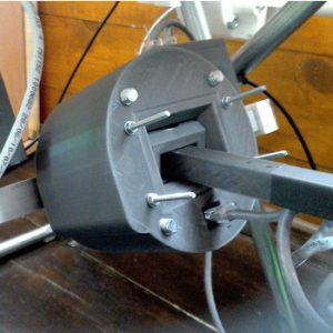
It is a cyclic gimbal, designed to simulate movements a pilot does in a real helicopter. A regular desktop joystick should be tilted to an angle around 40-45 degrees to reach its axis max or min value, while in a real heli you barely have to move the stick to fly, its more like applying pressure to the stick, and the nature of movements differs a bit. This gimbal can be mounted to the frame under the IKEA GUNDE chair, in a way you won’t even notice it is there when you’re not flying. Detachable stick allows you to take it off quickly when you don’t need it, serving the same purpose. There’s also an RJ45 socket for stick connection. Unlike V1 version, this one allows for center point adjustment.
WARNING! NO STICK CENTERING SUPPORT! IF YOU WANT STICK CENTERING, YOU NEED THIS ONE!
Components
4 * M8x80 bolts and nuts
4 * M3x40 (or M3x25) screws and nuts (use 3x40mm if you want to use Simchair MKIII yoke – currently in development)
2 * SS495A Hall effect sensors
4 * M3x20 screw for axes
4 * ZZ608 skateboard bearings
2 * M3x40mm screws
2 * M3x50mm screws
1 * ADS1115 external I2C ADC module
1 * Simchair MKIII I2C controller
Available mods
- 5x5x5mm magnet holders
- legacy press-fit type bottom lid
Special features
- force trim support – free stick mode
Downloads
Assembly
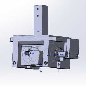
Print everything (STLS are positioned for printing, do not place cyclic connector part vertically on the bed), press fit SS495A sensors into their mounting places and fix them with super glue, bend sensors’ legs and solder their wires. Put cyclic connector part into an X-axis frame (short bearing axis should be on the magnet side), press-fit its bearings. Put X axis screws to strengthen it. Press fit two nuts into their sockets and insert 2 * M3x40 screws to fix the bearings.
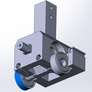
Insert X-axis frame into Y-axis frame the same way you’ve done it with the cyclic connector.
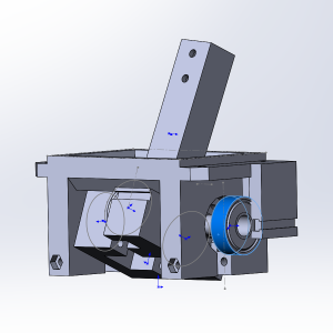
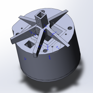
Screw magnet holders to their mount places, insert magnets and position holders roughly as shown in the picture below. Press-fit 2 nuts and insert 2 M3x50mm screws to fix bearings in their sockets.
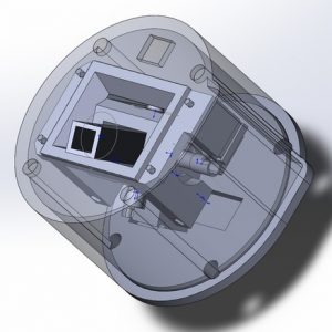
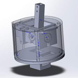
We are almost done. Insert the gimbal assembly into its enclosure and use screws to fix it. Use longer screws if you plan to use gimbal to connect a yoke (in development). Connect bottom cover with M8 screws after you finish with electronics and calibration.
Electronics
We will use a regular ethernet wire to connect our cyclic to the controller. You can take a crimped wire and cut it in halves or crimp your own. Connect ADS1115 ADC as follows:
VCC -> orange-white ethernet cable wire (5V) -> SS495A VCC leg
GND -> orange ethernet cable wire (GND) -> SS495A GND leg
A0 -> SS495A X-axis signal leg
A1 -> SS495A Y-axis signal leg
SCL -> green-white ethernet cable wire (SCL)
SDA -> blue ethernet cable wire (SDA)
Solder everything and proceed to calibration!
Calibration
To calibrate our cyclic, we can either use a serial port debug output on a master controller or use an X/Y axes cross in Windows game controller properties window (joy.cpl). Either way, we need to put a calibration device on first.
We have 4095 points per axis, so if we use serial port debug, we have to turn magnet holders until we are close to 2048. Some deviation is ok, but you may want to get close enough values.
To enable serial port debug, in an “.ino” file for the master controller, add Serial.print call to poll_cyclic function:
void poll_cyclic()
{
uint16_t x = cyclic.readADC_SingleEnded(0) >> 3;
uint16_t y = cyclic.readADC_SingleEnded(1) >> 3;
Serial.println(x);
Serial.print(” “);
Serial.println(y);
simchair.setXAxis(x);
simchair.setYAxis(y);
}
If you want to use joy.cpl calibration, simply position the cross in a center of a square by turning magnet holders. Do not use software calibration, as it will introduce jitter and reduce the resolution.
Download links
Simchair MKIII I2C latest software on GitHub
Hi Alex,
I think you have mixed up the bearings, because the Gimbal model is made for 608 bearings instead of the 625 you listed above.
Greetings
Lukas
Hi Lukas!
Oops, sorry for that, everything is made for 608 bearings, you’re right. Corrected the error =)