Summary
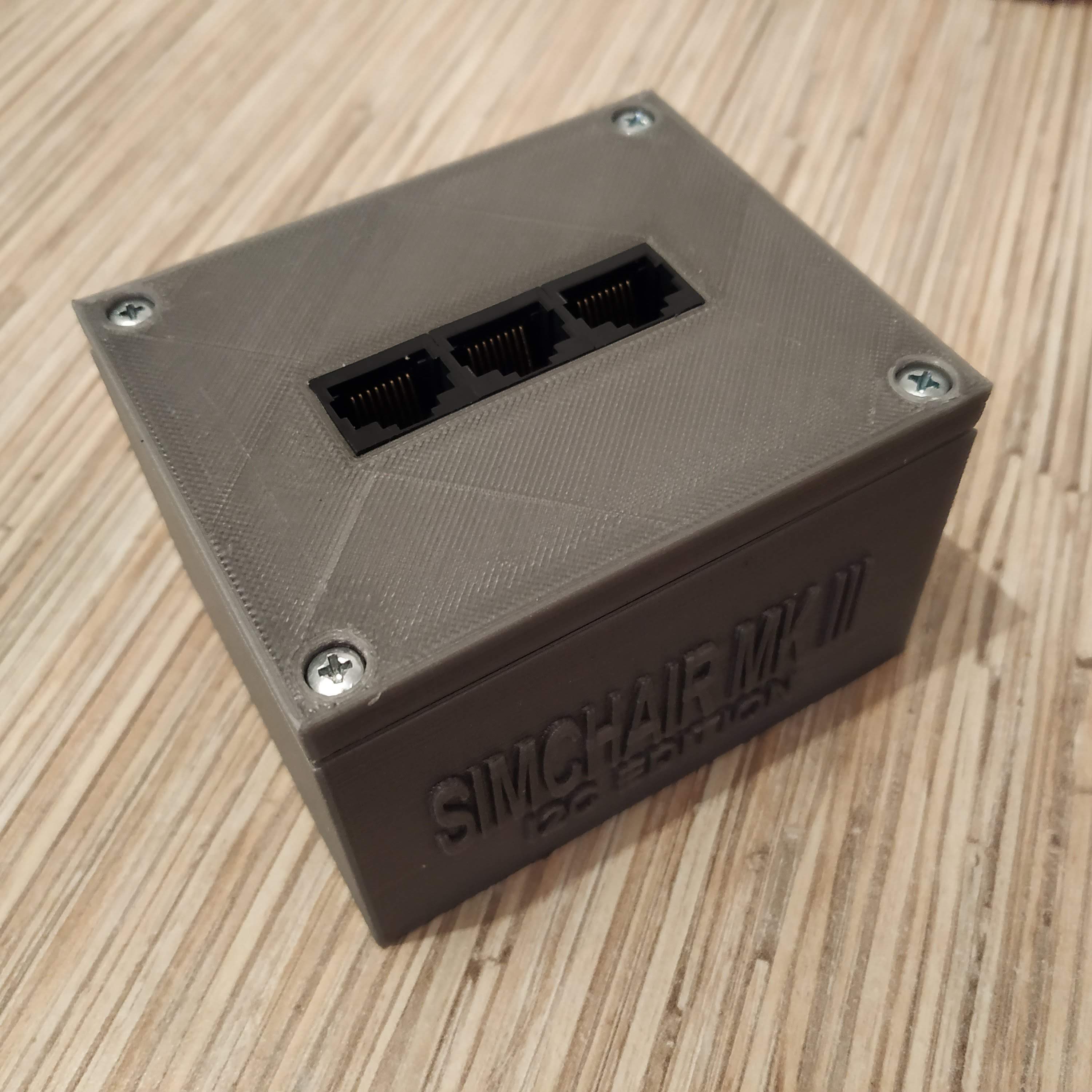
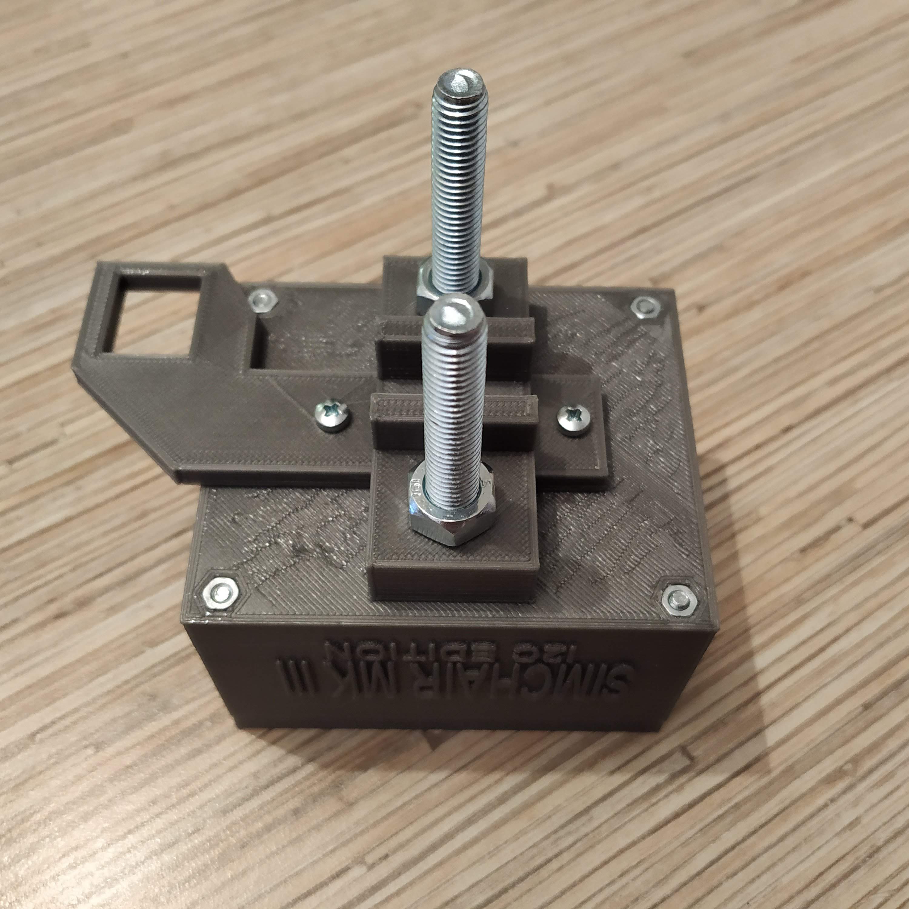
Simchair MKIII I2C master controller is the main “brain” of the set: it detects connected devices automatically and then loads device-specific configuration. It uses an Arduino Leonardo board. There are several cool things about it:
- device-specific configuration
- external I2C ADCs for flight stick gimbal and pedals
- unified interface for everything, buttons or axes
- peripheral-specific software-driven special features
- new features are added to the software frequently
- Joystick library by MHeironymus, which simplifies things like ten times; no need to mess with USB descriptors
I don’t think there’s any point in using an old analog version anymore, as there are now controllers with buttons (an old UNO – based analog controller only supported six axes as it had to do some massive filtering because of a noisy 10 bit built-in ADC)
Components
1 * Arduino Leonardo
4 * M3x50mm screws
4 * M3x12mm screws
2 * M3x16mm screws
6 * M3 nuts
3 to 8 * TJ8-8P8 sockets
ribbon cable
hot glue
Available mods
- housing lids with 6 and 8 Ethernet socket slots
Downloads
Flashing and configuration tutorial
Assembly
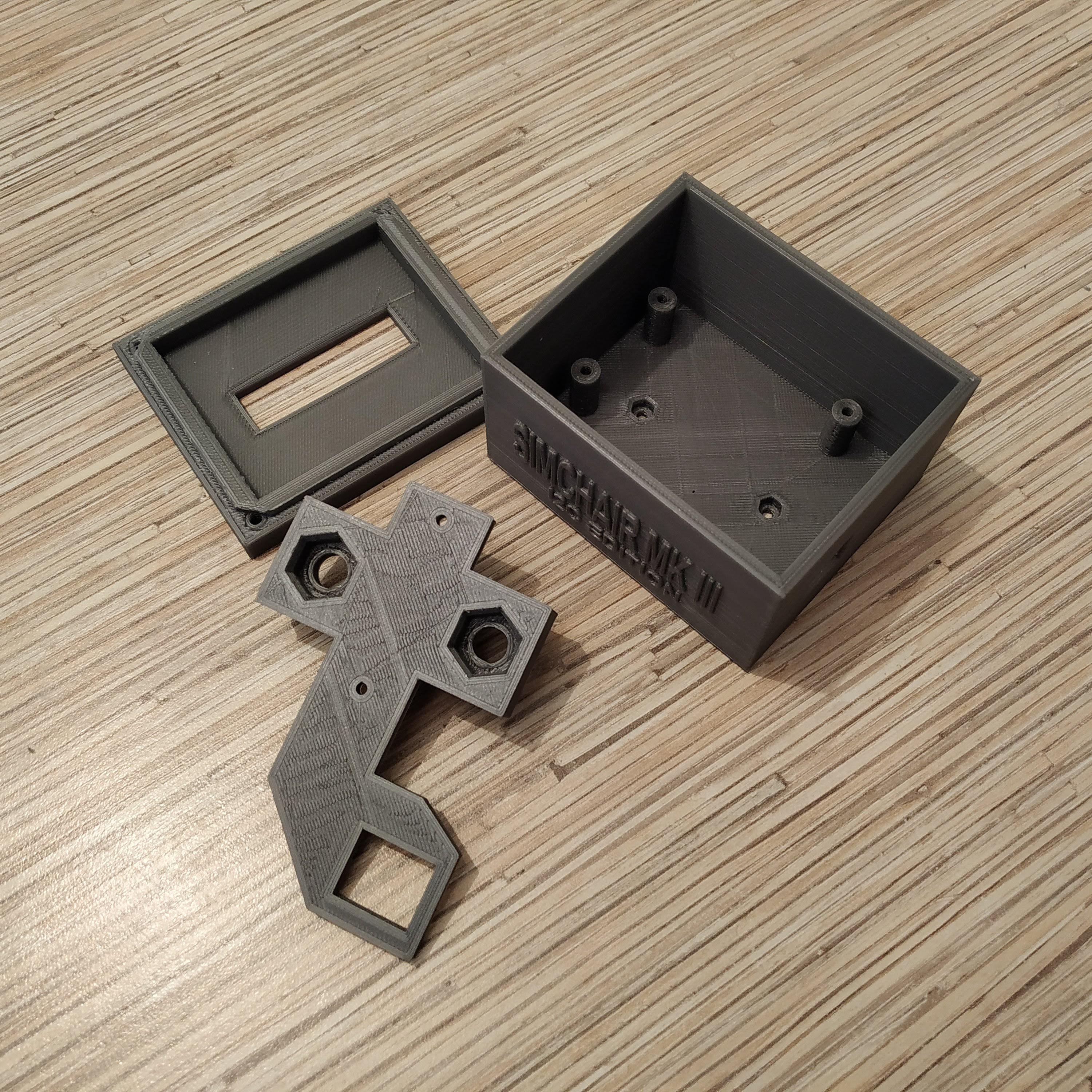
- Remove supports from printed parts.
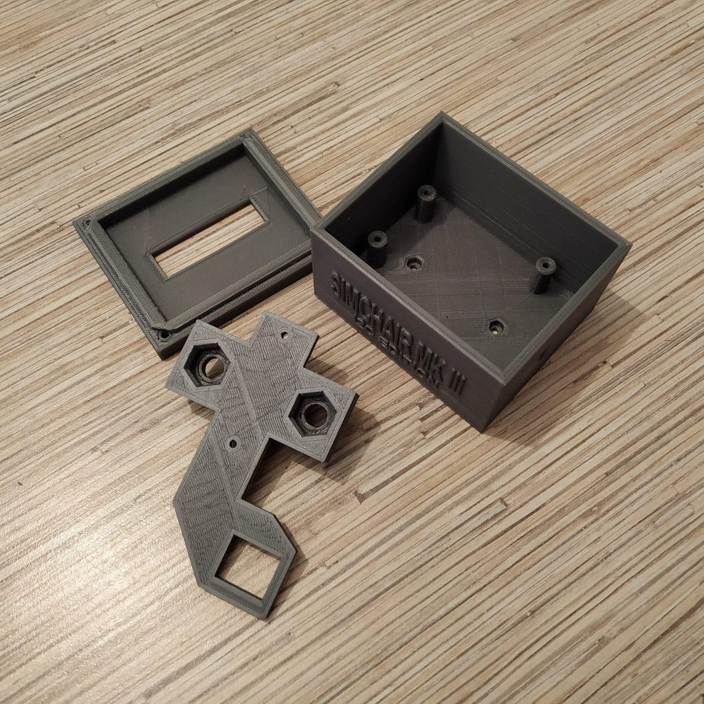
- Press-fit M3 nuts into their sockets in the enclosure bottom part.
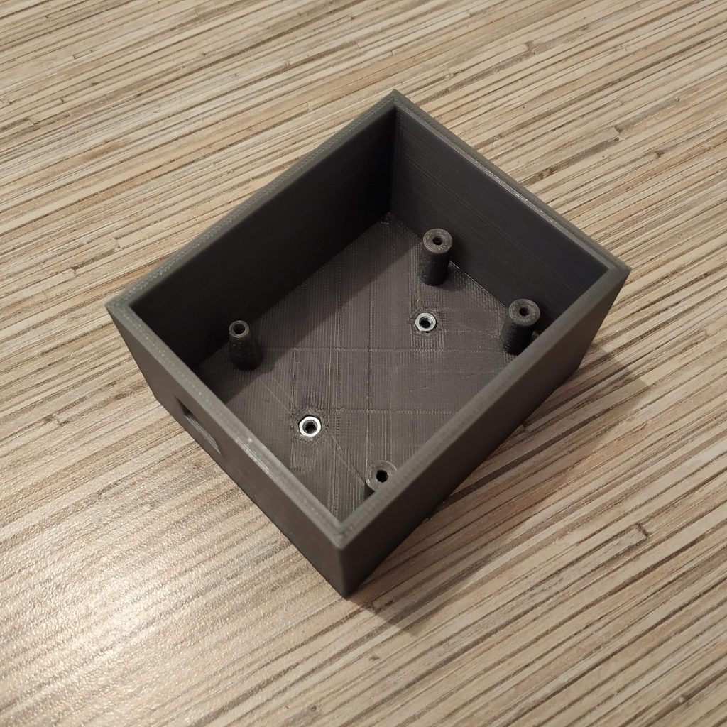
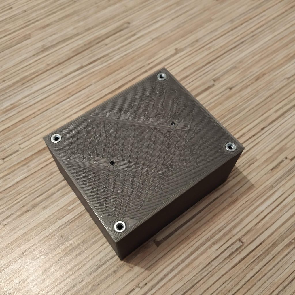
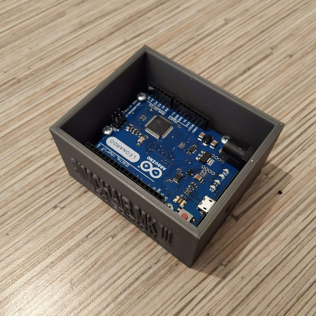
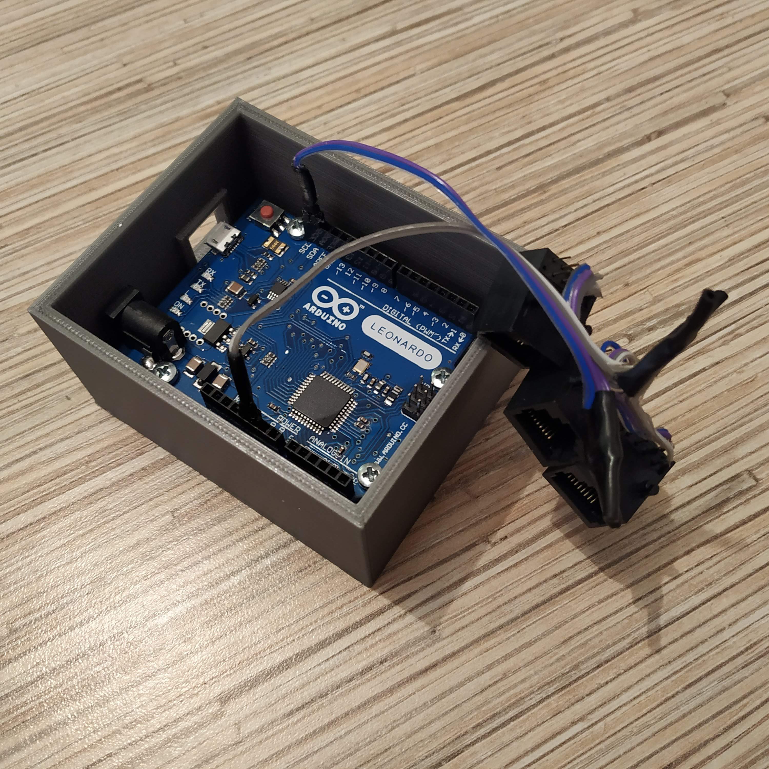
- Inser Arduino Leonardo board into the enclosure and fasten with 4 M3x12mm screws.
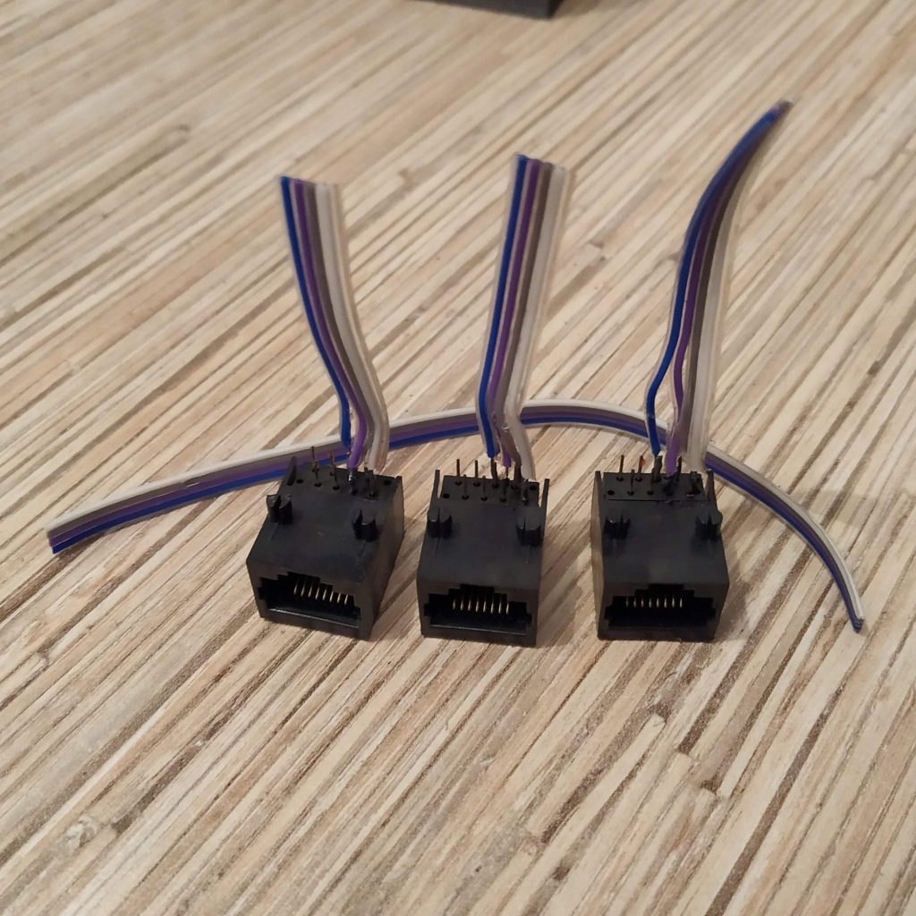
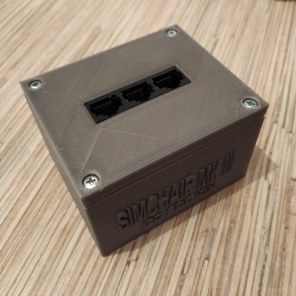
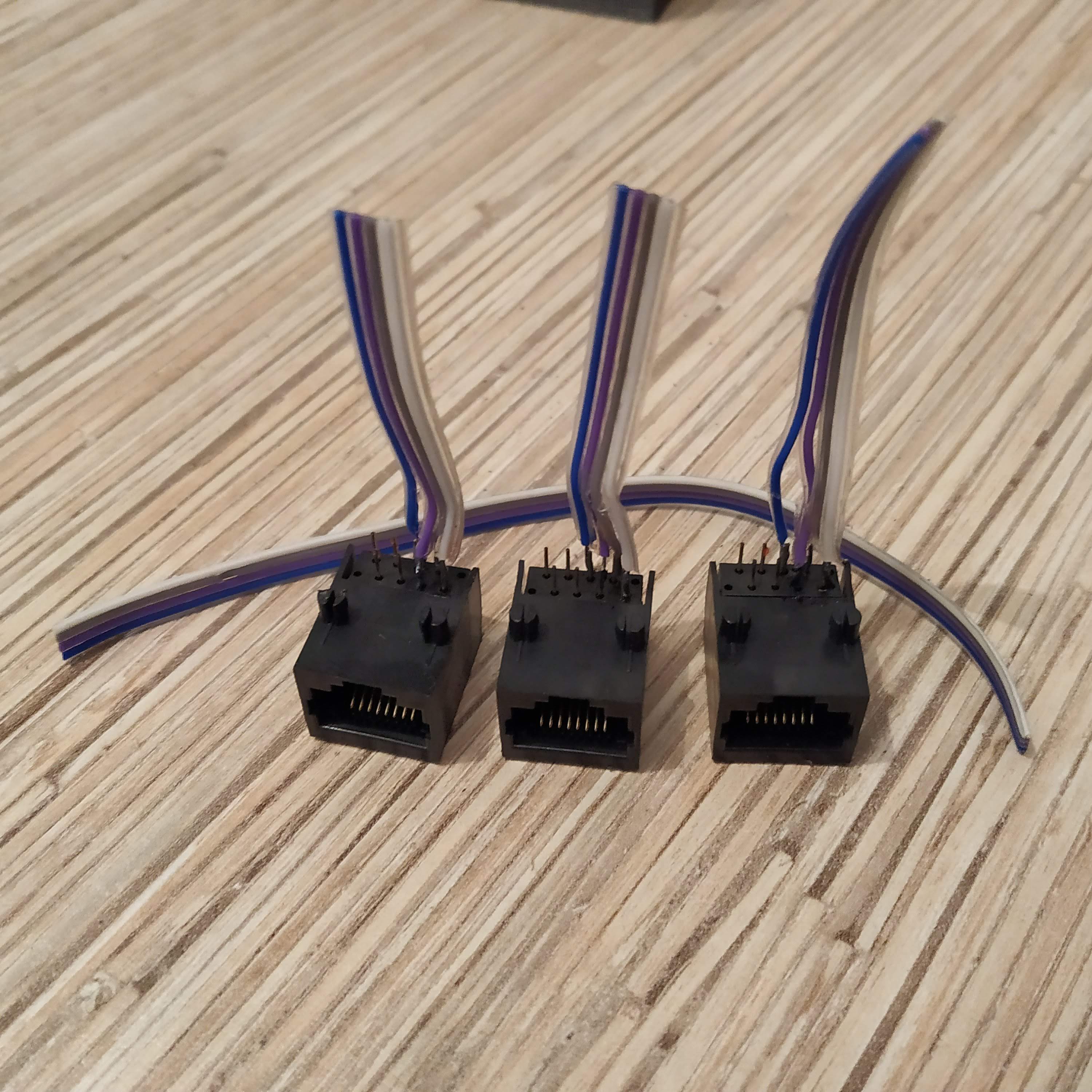
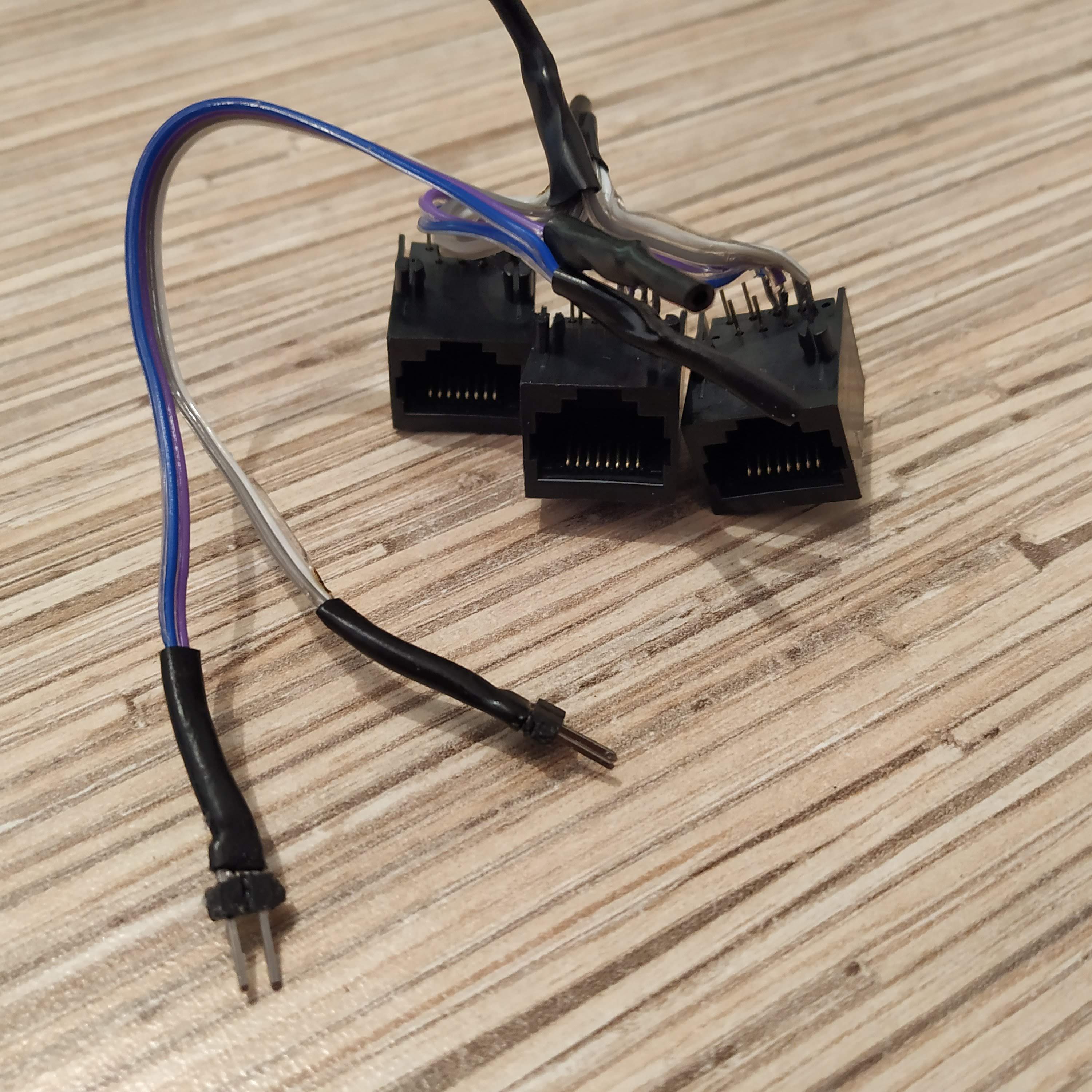
- Solder 4-wire cables cut off the ribbon to 1st 4 pins of Ethernet sockets (pin 1 is where the orange-white wire is in the plug, pin 2 is the next one in another row, housing lids with slots for 3 to 8 sockets are available under Mods directory, we will be using a default 3-socket lid for this tutorial)
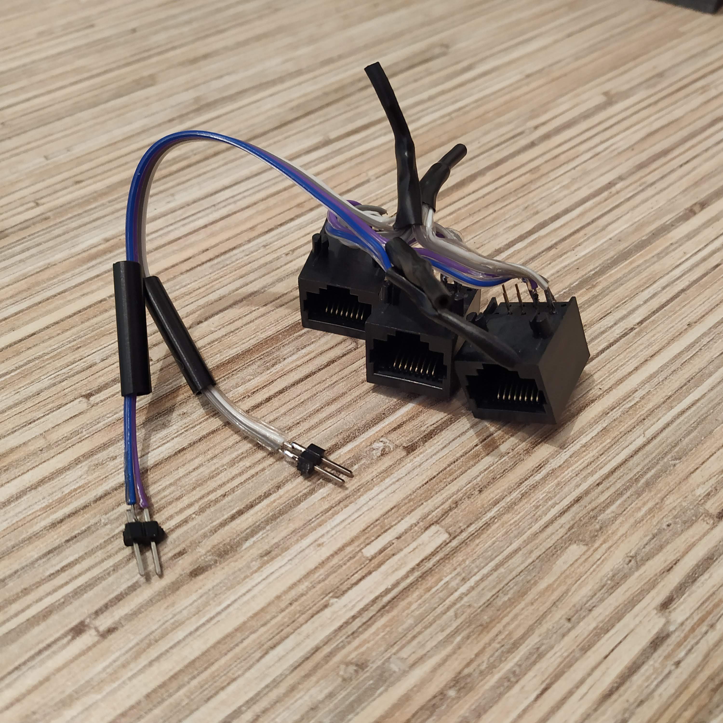
- Tie wires together by their pin numbers, and use another 4-wire cable to connect sockets to the board. Split that 4th cable into 22-wire cables and solder 2-pin headers to its ends. Use hot glue and insulation to strengthen them.
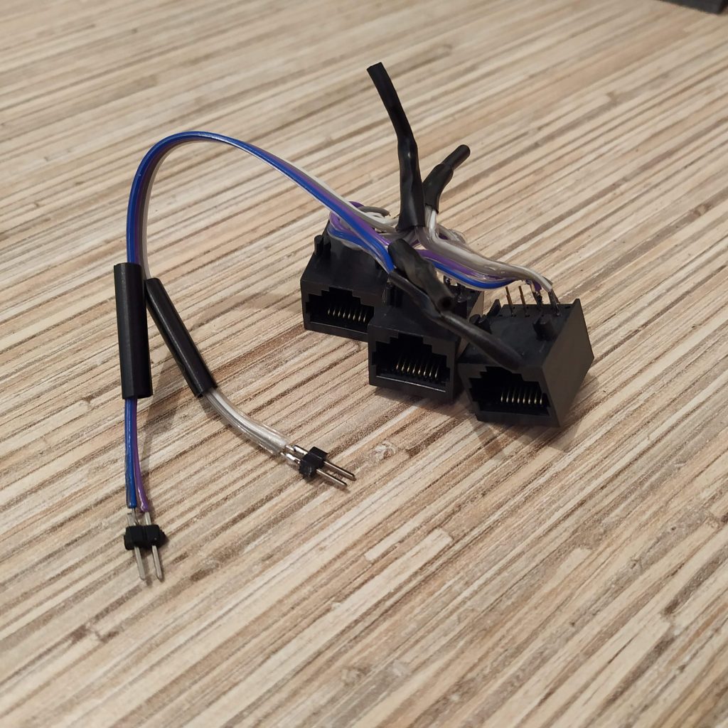
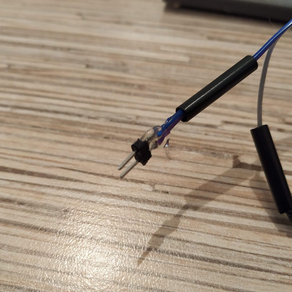

- Connect sockets to the board (5v, GND, SCL, SDA pins), flash it and check that all sockets work by plugging something to it (after re-plugging stuff, reset the board). If everything works, go on!

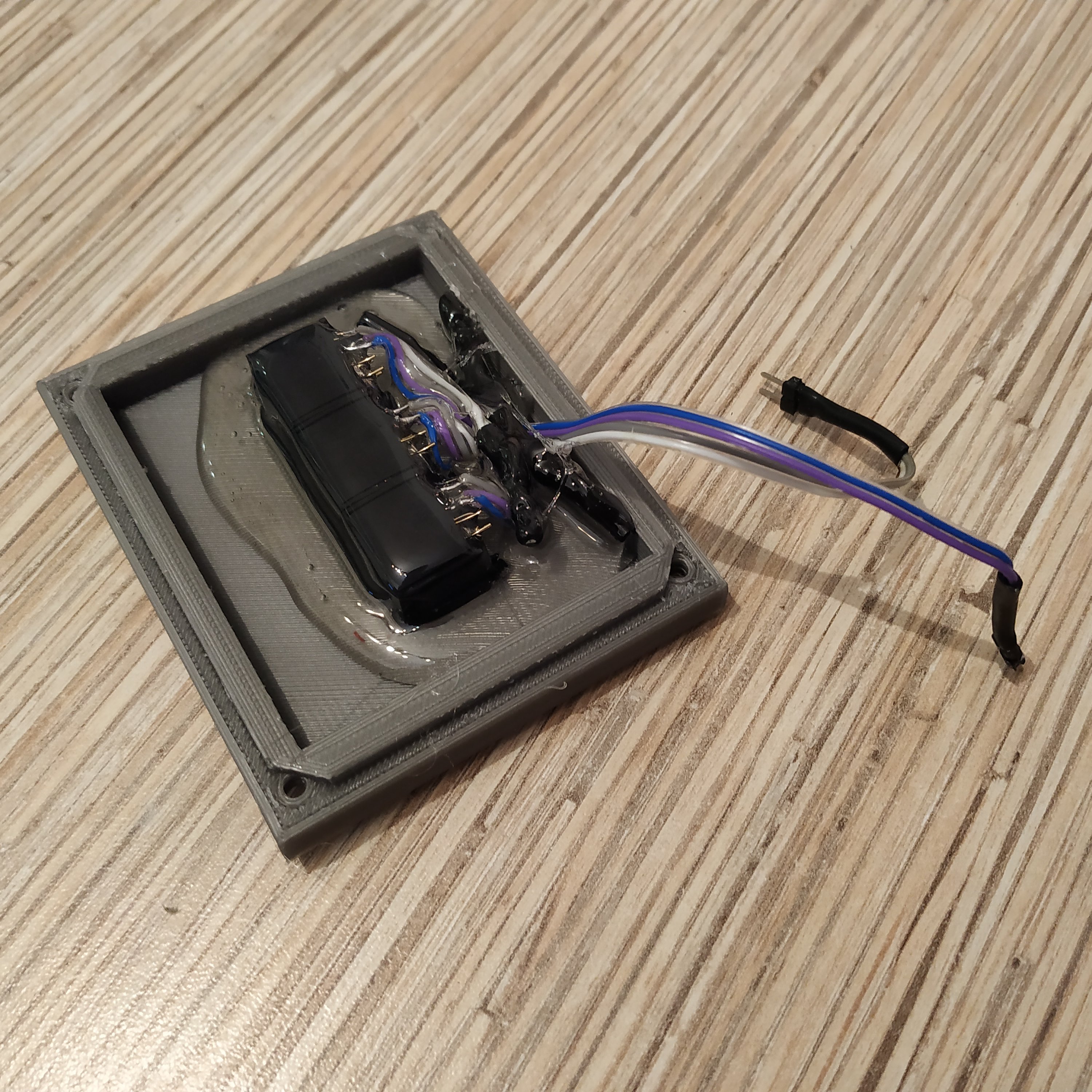
- Press-fit sockets into the lid and pour enough hot glue to fix everything in place properly.

- Connect pin headers to the board and put the lid on, use 4 M3x50mm screws to fix it.
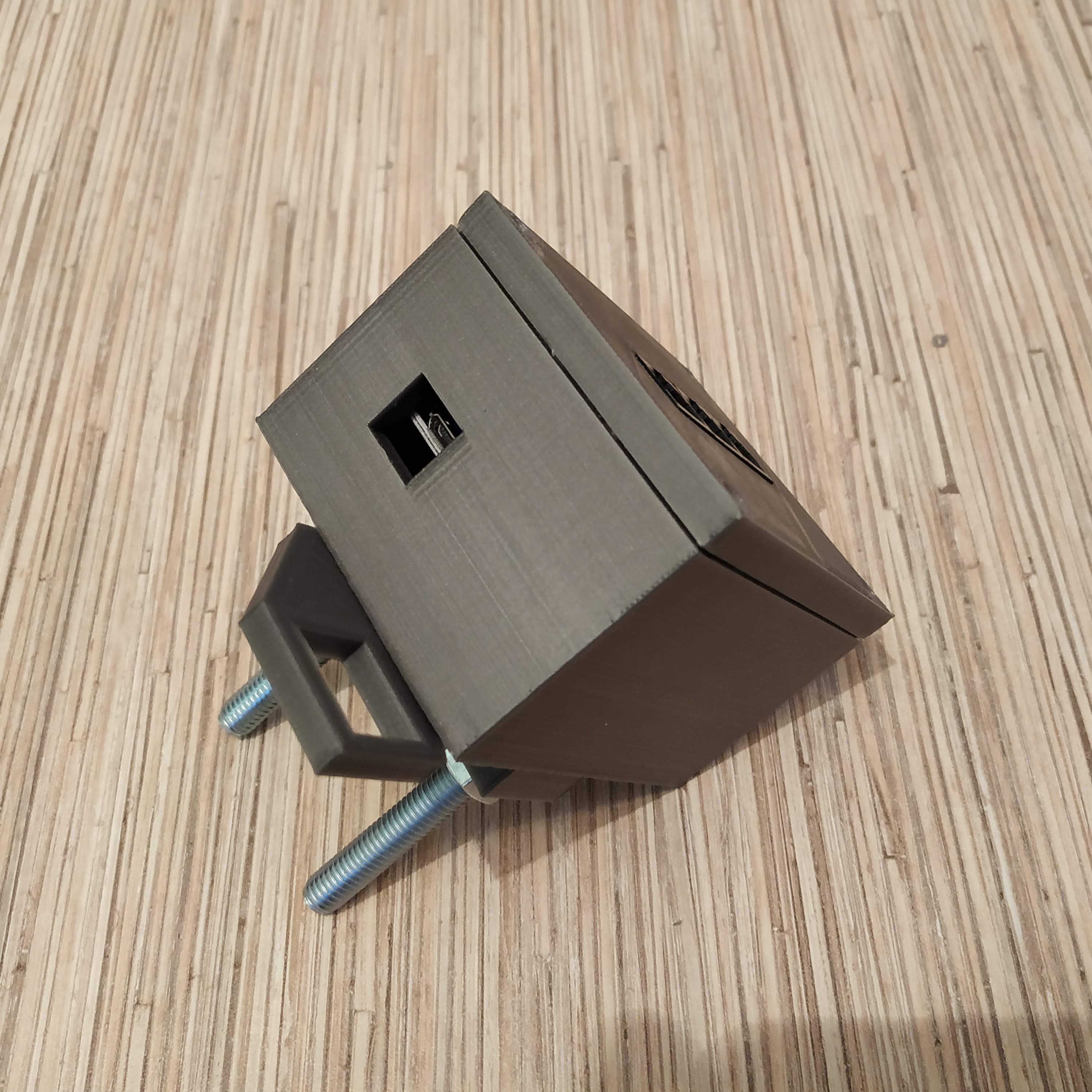
- Insert 2 M8x50mm bolts into the mount part 1. Fix with nuts from the other side.
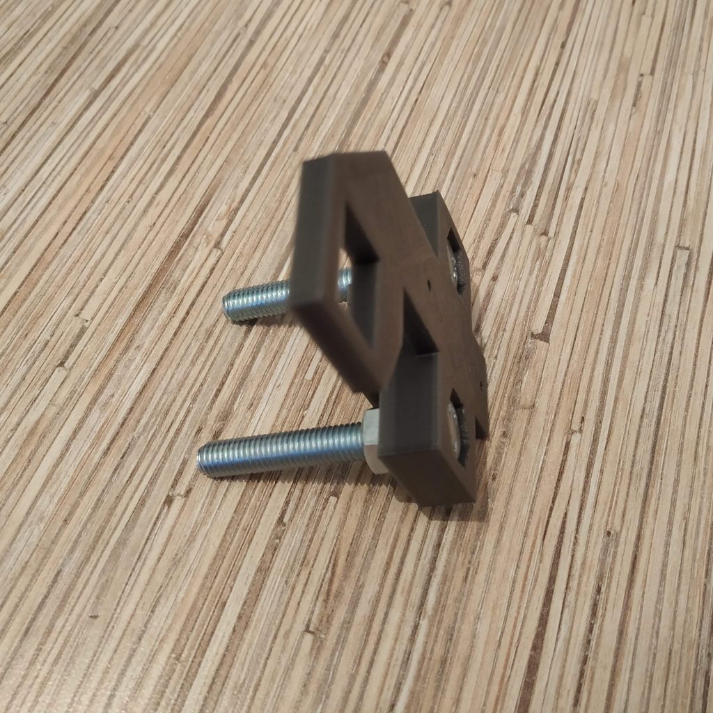
- Attach the mount to the controller housing with 2 M3x16mm screws (MAX 20mm!) . Put part 2 of the mount onto its bolts.
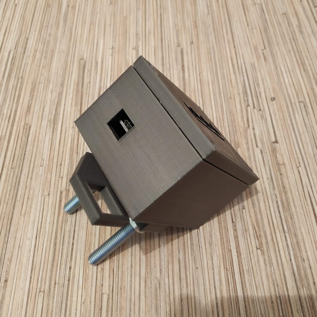
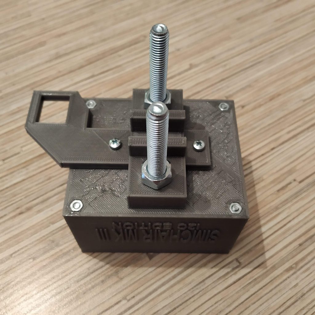
Congratulations, you have finished the master controller assembly!
We will be using this connection scheme for all of our devices:
SOCKET PIN 1 – VCC
SOCKET PIN 2 – GND
SOCKET PIN 3 – SCL
SOCKET PIN 4 – SDA


You can try flying with it right now, or read about firmware configuration.
Hi Alex,
I’ve spent most of today familiarizing myself with your work and researching the bits I don’t know. I’ve gone through all of Peter’s work and whatever documentation of yours I can find, but I still have a few questions. First, I understand there’s a box which contains the main leonardo board, but where are the pro mini boards located for each peripheral? it looks like there’s a pro board fitted inside the collective head, so is the collective mini board located in the base of the gimbal? Lastly, how are the ADS1115 i2c busses connected? I’ve used an arduino for my printer before, but most of this is going to take some work to understand on my part.
Thank you!
Ben, if you have more questions, please feel free to ask them =)
Every peripheral is a separate device, it has its own Arduino pro mini (except for cyclic gimbal and pedals which have ADS1115 boards inside (they are connected directly to the master controller via I2C because of how i2c library works) and a 412 head that has 2 pro mini’s in it). Everything is connected together through I2C, with ethernet cables. First 4 wires of the cable are used, white-orange for 5v, orange for GND, white-green for SCL, blue for SDA.
ADS1115 are used for a higher resolution of axes in most critical parts (you can only have 4 of them connected simultaneously because of address limitations). Basically, you either put boards into correspondingly shaped slots or just stuff everything in and screw together (collective heads). In “scale” stuff like the B8 stick grip and the Huey collective head, you have to do some cable management for wires to fit in a tight enough space =)
Devices with axes require some initial mechanical and software calibration after assembling (takes around 5 minutes), collective heads and a cyclic grip are pretty much “flash and fly”.
Cheers!
I’m just preparing to do my build. What are the dimensions of the RJ45 sockets you have used? I’ve measured the cutouts and it looks like the cutouts support 15mm wide by 12.8mm high sockets but I’m having trouble finding sockets with those dimensions. Most I can find are 15.8mm or so wide which would make the gap to fit them in 2.4mm too narrow. Huge thanks by the way for sharing your project, I can’t wait to retire my X56!
Hi Andy! You’re right, the dimensions are 15×12,8mm. It’s a TJ8-8P8 socket, I bought it locally. There are a few different types, so sadly it’s a bit of a pain (couldn’t find any links on ebay or aliexpress!), but I think you can find something similar in a local electronics store! There are shielded sockets, some of them will fit with the shield removed. Anyway, you can always file the hole or a socket a bit or just glue it to the outer side of the part =) Alternatively, if you want, I can buy some and send to you, along with Lada clutch springs if you need them =) This may take some time, however.
Cheers!
I also can’t find connectors the right size – i may try to modify the parts on each to fit the jacks I can get my hands on – should be just measuring the face of them and making a hole that big (x3) and boolean subtract? that’s my hope! (I don’t even have a 3d printer yet, but I’ve been reading!)
just tell me their size, I will make a modified part for you, no worries =)
Amazing!! Thanks! Waiting for them to arrive 🙂
Still working on sourcing parts here in Canada, and have a few questions – thanks so much for all the amazing support!
Magnets :
I have have found some 5X3x3mm and 5x5x5mm magnets, but cant find the ones you call for – can 5x5x5mm be used with your existing mod for both the gimbal and the collective magnets?
I’m not sure if the size of them, relative to the hall effect sensors is important?
Do they simply sit in the magnet holder and get glued on to the end of the bolt?
Switches :
I want to use the huey head on my collective, but perhaps with slightly less switches as I’m trying to keep the whole rig a bit generic to simulate all sorts of helos. Can i simply put in a SPDT switch in each spot and have that only return 1 function to the joystick software? (I haven’t researched the arduino as it’s not here yet 😉 But I hope to be able to pick up your programming fairly quickly.)
I guess I am wondering if there is anything MANDATORY to include in the collective head?
I’m so excited to be working on this. I am beyond impressed with the look of the final product you have shown in your video. I hope we hear from others who have their builds to share! I’ll post some photos as soon as I have some solid to look at 🙂
Wow – I forgot these questions!
– If I want to modify the models a little to include a cavity for a switch that is a slightly different etc, what software do you recommend to modify them? I am a little rusty but have background in 3d modelling.
– 10×20 aluminum for the chair… i can easily find 3/4″ square aluminum tube… lol
thanks again so much!
Yup, 5x5x5 magnets can be used – make sure to print the modified collective housing from the latest post though, so if smth goes wrong, we can adjust the holder without disassembling the whole thing!
The size of magnets is important, the width of the magnet defines the travel range of the lever. Don’t remember in what way exactly, but I think that wider magnet = more range!
The Huey head is great, but I will be releasing the lever with a Bell 206-style mechanical idle stop latch very soon now, and it would look a bit weird with it. Consider choosing the 412 head and the new lever instead, as it’s something that a lot of people (me included) wanted for a long time!
As for switches, I don’t recommend you using any other configuration than the stock one. It will generally limit the functionality of the head and will cause all kinds of pain when upgrading firmware. Trust me on this one, collective heads are designed in a way that makes them suitable for most applications (4 switch modes + mode switch), and the 3-way switches are really most useful. You can always configure and use them as 2-way switches, but having more options is always better than not having them =)
So unless you really want something totally different and custom, I doubt there will be any point in changing anything in the design of a head. Btw the Huey head is a semi-scale one, so it has really tight space inside of it!
About the software, I use Solidworks 2016. As for aluminum tubing, check this link:
https://www.onlinemetals.com/merchant.cfm?pid=22324&step=4&showunits=inches&id=1634&top_cat=60
It’s some US shop that sells it, maybe shipping fees will be reasonable. Alternatively, just modify parts to suit your needs!
Cheers =)
Thanks again so much for the replies! I have most of the gimbal printed and I’ll do the main controller box tonight.
Back to switches : I’ll go for the head you recommend of course, and would love to have the new models before I create my collective. (plan for me is main controller – then gimbal and stick, then collective, then pedals). I am having trouble finding switches like the ones used in your plans (6 pins and 2 positions that are spring momentary?) My concern is : If I don’t use EXACTLY what you have, will I even be able to create a config that works for my gear?
Can you tell me the specs of the switch so I can search for them? Are the SPDT or DPDT or ?? thanks again and apologies for all the questions as I get up to speed.
wow i should have looked on Ebay for switches! If you give me the exact specs for the sort I need, I am sure I can order them – Thanks again so much!
Sorry, my bad, 1st thing that popped up by googling SPDT was a 3d-printer endstop type lol!
Surely SPDT or DPDT switches will suit as long as they will fit physically! Only 1 contact group is used, so any type will do. You can use spring-loaded type, or toggle type, just choose the one you prefer. This one: https://ebay.to/2Vm8fHU is a larger momentary, https://bit.ly/2IBYq78 this one is a similar toggle-type, for smaller switches – https://ebay.to/2U6Av0J MTS-103 toggle type, https://ebay.to/2GJpVtz for MTS-223
You can ofc make your own configuration, and alter the code for it to work =) Will just need to merge stuff at every update then. With all stuff assembled as per manual, you may only have to replace head switches configuration lines when reflashing =)
P.S. with more heads coming soon I will probably have to do something with how they are configured in software. For now, all configuration for every device is stored in a single file, but it may have to change as we’re pretty close to limits of Leonardo board. Heads with 4 switch modes, as it is implemented now, consume quite a lot of memory =)
For now, I’m thinking of choosing the (one) head model you want when reflashing (as there most likely will be one head per user), or maybe even making a separate device with a display, dedicated to configuration of Simchair. Anyway, at some point, the number of compatible devices with their functions will exceed memory limits of the board, so smth will have to be done with it =)
Cheers!
This is such a great project but I am getting lost in the details as I try to actually continue the build.
The master controller standard cover has room to mount 3 rj45 sockets. that does not seem to be nearly enough, so do most need the 6 or 8 jack cover?
I’m building the pedals, simple collective, reinforced gimbal, b8 flight stick, 412 collective head and possibly the throttle quadrant. doesn’t each one of these peripherals need to connect to a socket on the master controller via its own ethernet cable? so i would need 6? or go with 8?
if i go with 8 sockets , are they all in parallel, like the tutorial shows for 3 socket lid?
is there a master wiring diagram somewhere? or at least a block diagram?
thanks
mike
Thank you! =)
Three sockets are sufficient for a helicopter setup (and probably for all other as well – we’re about to face the limits of a single Leonardo board anyway).
The thing is, only the gimbal, pedals and the collective go in there, the B8 stick is connected through the socket in the gimbal, the collective head is connected with a cable that goes through the lever. I am now in the process of developing a better version of the throttle quadrant, that will have at least 2 sockets on it as well, so it can be used as a hub =)
All sockets are connected in exactly the same way, basically in parallel:
VCC -> Tj8-8P8 PIN 1 (white-orange wire)
GND -> Tj8-8P8 PIN 2 (orange wire)
A5 (SCL) -> Tj8-8P8 PIN 3 (white-green wire)
A4 (SDA) -> Tj8-8P8 PIN 4 (blue wire)
Something close to a wiring diagram is mostly present for each peripheral, at least in a form of the description =)
Cheers!
dear alexey, my build is progressing but i am having static failure of the gimbal spring mounts. 2 of the 4 broke all by themselves as the assembly was sitting overnight not being used.lthey are fracturing at the reinforcement plate at the top of the gimbal assembly, right where the hex bolt and reinforcement washer are.
so i am reprint all the spring mounts and am making sure i get a good 210 C print (using PLA), and I have screwed the spring bolts all the way in to reduce the spring pressure as much as possible. i am using your recommended springs. any other tips?
i have a picture of the way they broke, but see no way to post a picture to you.
as always, THANKS for such a great project.
mike
Thanks for your kind words, Mike! What infill settings and layer width do you use? Seems a bit strange to me as these should be pretty strong (I am using that gimbal for quite a while now, and none of them broke yet!) Do you print them one by one or all 4 at once? If so, try printing them 1 by 1, this way parts seem to be stronger.
I am planning to make a pneumatic mod for cyclic soon as a few IRL pilots told me that the controls need some friction on them, that may be better than springs =)
Let me know if you will still be having problems with them if printed 1 at a time with high infill percentage and larger layer height, we may add holes for bolts to strengthen them. Are you sure you’re using the clutch pedal spring, not the brake pedal one?
Thank you for the tips. They were very useful.
I was printing 2 at a time. i will print them individually now.
My infill was set to 40% in slicr but my print program was over-riding it to 20%. I fixed that, so it will now be 40%
My layer height is set to 0.2 mm.
I am using Lada Niva 1600 1700 Laika 2101-2107 Clutch Pedal Retracting Springs. I hope these are the right ones because they were very hard to find.
One other quick question please. The collective. I am doing the pneumatic mod and have the recommended 150 mm cylinder. there are two 5 mm screw holes (one in each end) that let air in and out as the cylinder is moved. should i seal them with setscrews or partially seal them or what?
thank you so very much.
20% is really too weak, I think once you will print it at 40%, it should be fine =). Also, I recommend using thicker layers – 0,3 or even 0,4mm. If you feel that these springs are too tight, feel free to try other, softer ones =) They are there just because I had no dedicated spring shop around and it kinda hard to find a place where you can look at them and touch them to test if they are too stiff or too weak except for car parts stores.
I am pretty sure the recommended length was 100mm, but you can go with 150 just fine as well =) Or is there an error somewhere? Absolutely no difference, it’s just the 100mm one is more compact (you may need to make the vertical rail a bit longer). Just put 2 short M5 screws in there (like M5x6mm or M5x10). Make sure screws do not touch the piston! Just screw them in for a couple of turns. You may want to add some stiffness with the friction tensioner as well to make it more realistic. The goal is to make it absolutely smooth, but with some friction, and it should be able to hold itself in all of the lever’s range, regardless of the head you choose to put onto the lever.
Cheers!
Hey there,
thank you for putting so much time into this. It really is a great design!
Unfortunatly I ran into an issue. I’m using the single engine collective with the huey head and after flashing and calibrating all the boards I tried to use them all together, so I wired the Leonardo to them but as soon as I connect the ethernet cable the thing goes black. There seems to be not enough power to sustain the head and the lever. If I disconnect the Head, everything works fine but with it there is not enough power. Any idea where I went wrong?
Thanks in advance!
Hi Matthias! Thanks for your kind words =)
Regarding your issue, a lack of power is highly unlikely the case!
I would rather suggest something is wrong with the head itself. Does it work when connected alone? Are you sure the wiring in both Ethernet socket and the plug is correct?
Note that you have to connect everything BEFORE plugging the USB cable, as things are auto-detected on startup of the Leo board.
Cheers!
Hey, thanks for the quick answer!
You were right. I opened the head up again and found that by closing the lid, I accidentally connected the 5v and GND ports of the joystick. After reconnecting them properly and fixing everything with a bit of hot glue together it works perfectly now.
Many thanks again!
You’re welcome, mate! Thanks for supporting the project, appreciate it =)
Hi ,
For long time i read your site and your work and plane my project to start .
for now i make a full Excel list of all the items i need to buy befor starting to print (Scrow, Nuts,Springs,Electric, Etc …)
For the last days i found that u made new version of the SimChair and now we talking about MKIV .
I found that Master controller is still MKIII.
So first qustion is if Collective Base MKIV Will work with Master controller MKIII?
Also i cant figer what i need to create and build for single engain collective with UH-1 Head (I fly in DCS).
Did the MKIV replace the single engain collective base ?
Last but not least for now is how can i create Master controller with more than 3 sockets to create my own Joystce and grips (like to use this platform to create a full F-16/F-18 HOTAS)
Thanks Alot for your outstending work and design
Assaf
Hi Asaf! Thank you for your kind words!
The master controller is, in fact, MKIV already, it’s just, the manual is not yet there. Which is not really a problem – the thing is only a box for an Arduino Leonardo!
Collective base MKIV can be flashed to work with MKIII master firmware, however, I don’t recommend doing that as MKIV is better in every way. A huge feature of the new collective base is pedestals – which are only supported in MKIV firmware, throttle filtering, mode switch on the base, etc.
To make an MKIV Huey collective, you can make an MKIV base (follow its assembly manual), then take lever body parts from here and then make a Huey head. Both lever body and head can be made using MKIII instructions, nothing has changed there. I will port the Huey head to the new software in a few days.
The new master controller has 4 sockets. For a full cockpit, you will need a lot of them, and even more Pro Minis for peripherals! The limiting factor is its RAM rather than ports (just add as much as you need in parallel). Thankfully, controllers are now infinitely stackable by design. You can easily add your own software for your devices (I will make a separate video guide about how to do that) and choose what device goes to which controller. Making a full cockpit is a huge project, do you have some experience with programming? You will definitely need that. Please feel free to ask questions! =)
Cheers!
WOW !
Thank for your reply.
I not plan to make a full cockpit since i use VR.
I plan to make only the HOTAS.
I keep u update in my progress.
PS
The new MKIV section on the site not have the Comments option 🙂
Ah, I see, that’s much easier =) You’ll be fine with only one master controller then =) Thanks for pointing the comments thing out – fixed that.
I need some clarification on the FLASHING process of the Master Controller.
I have verified my wiring several times to make sure it is correct.
I connected the wires from the PL2303 device into +5VDC, GND, TX (to RX) and RX (to TX).
I placed the PL2303 USB device into the PC USB port.
The Leonardo board shows a Green LED and Amber LED after plugging into USB post.
The Arduino flashing software is opened up Leonardo board is chosen and COMM 16 is chosen.
After compiling I get error messages and a missing (.h joystick librbary).
I am not sure how to correct this.
Then when I I follow the instructions for the Foot Pedal, it states to hook the pedals to the Master Controller and prepare to FLASH. How do you hook the PL2303 into the Leonardo at the same time the Ethernet ports are plugged in? There is only (1) +5VDC plug that I can see. do you have a picture of this flashing setup?
Hi! You kinda mixed it all up.
1) Plug the Leo board into usb.
2) Install libraries from z_libraries folder (copy them to your Arduino/libraries folder)
3) The software will compile after that, select the com port marked as Arduino Leonardo and press upload, it will flash the board.
4) After you’ve sorted out the process, choose your hardware in device definitions tab and calibrate your devices where needed (cyclic and pedals require only physical calibration – rotate the magnet holder bolt until they will be centered in joy.cpl in windows, for calibration of the collective, please watch the video about the process on my channel)
5) PL2303 is really outdated, its better to use FTDI232 board, even then, in a couple of days I will be rolling out the new master which will use the leonardo board itself to flash the peripherals, along with the manual for it =) Perfecting tolerances of the box at the moment. Those boards are simply USB to COM adapters and are used to flash the Pro Mini boards that do not have USB onboard. Pedals and cyclic use ADC converters which do not need to be flashed – you just connect them to the master and adjust their center physically rotating the bolt that holds the magnet.
6) please feel free join our DIY discord channel: https://discord.gg/vezbpxyyEP
7) Please watch a couple of videos that try to explain how to do that:
https://youtu.be/Al-26v-Bnng – simchair4 software tutorial
https://youtu.be/fu-ddi6CIWA – how to calibrate the collective
P.S. Just noticed which page you’ve left the comment under. There is little sense in using the MKIII version of the software as well as the old MKIII box at the moment IMHO, please look at the MKIV version of the controller.
Cheers!
hey, can you explain to me why you used linear pots in the throttle quadrant? since its rotating, shouldn’t it use regular pots? excuse me if this question is stupid, im kinda new to this stuff
Hi! I only used linear pots in Cessna-style quadrant, the stackable one uses regular pots =)