Simchair MKIII I2C latest software on GitHub
Summary
Simchair MKIII uses the I2C bus for communication between the master controller and peripherals. That means that every controls piece contains a separate Arduino inside. Why is that necessary?
- we can use a device-specific configuration: a lot of nice features are already there
- we can use external I2C ADCs that provide MUCH more precision
- we can have more than six analog axes and all the buttons we need
- we can use filtering when it is necessary without slowing the master controller down
- we can extend our controller’s ports more than we’ll ever need
- unified interface for everything, buttons or axes
- Leonardo board allows us to use a nice Joystick library by MHeironimus, which simplifies things like ten times; no more pain with USB descriptors
- easy flashing; need to change sensitivity setting for an aircraft? turn the AP on and flash the controller in flight!
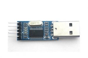
Arduino Pro mini is used for all peripherals. It doesn’t have a USB port on it, so you will need a USB- UART converter to flash them. Why use a board with no USB? They are small and cheap, and the converter costs literally nothing. I use a PL2303 based converter:
You can opt for using another Arduino board, like nano, everywhere except the B8 stick grip (probably not 412 head as well) at the moment. Basically, all you need to do is flash all the boards with their corresponding software and wire everything as written in manuals of the peripherals. Note that the master controller software is frequently updated, so remember to check GitHub for updates. Software for peripherals is only updated when there are some severe bugs in it, or some major upgrade is needed to adopt new functionality (I understand no one wants to disassemble stuff to upgrade it). With this in mind, you will only need to change something in peripherals’ software if you wired stuff differently.
Download
Download simchair_i2c repo from GitHub.
Libraries
At the moment, the master controller sketch uses two libraries:
You will need to install them to your IDE to compile the software.
Configuration
The sketch is split into multiple files for better readability and easier navigation. Every peripheral device has its own file, and all stuff you need to calibrate it is in there (if there are any, steps that are needed to be done for calibration are described in peripheral’s assembly manual). When you open one of the files with Arduino firmware, it opens the whole project, and all the files are opened as tabs. When you compile it, these files are concatenated in alphabetical order.
All configurable parameters are under “configuration” tab (a_configuration.ino file), it’s documented right there in comments. ( lines, starting with // )
Extra
To install Lua script that adds collective head switches support key bindings to X-Plane 11 controls menu, please look at this post.
Hi Alexey – have an understanding problem with master controller software as it is split into several *.ino files numbered with a to z. What do I have to do to get one sketch to transfer to the Leonardo?
Hi Guido! Just open any of them. Arduino IDE will load all of them (as tabs) and merge into a single file (in alphabetical order, that’s why the letters are there) during compilation. The whole thing with splitting the config to multiple files is just for a better readability (there’s a quite lot of code now). Do not forget to install joystick library (https://github.com/MHeironimus/ArduinoJoystickLibrary) and ADS1x15 library (https://github.com/adafruit/Adafruit_ADS1X15).
An important thing is to select Leonardo in boards menu and choose the right COM port. After that, just press “flash” button.
It will show up as 3 joysticks, the gimbal will work as X and Y axes of the 1st one =)
Hi Alexey! To get the tabs in Arduino IDE it was necessary for me to download all files into one directory. In my case I named the directory into “master_controller” and opened the same ino file. Is this the right approach? I get then a lot of error messages, unfortunately too many to send here in the comment. I use Arduino IDE 1.8.7. Possible to send to you by PN?
When I downloaded only one ino as you wrote above the lines of the other inos are loaded but not seperately in tabs. Error messages are then the same when conmpiling. I am lost now!
Guido
Oops, I thought you have downloaded the whole git repo (actually, the best thing to do).
Yup, you need all files from master_controller directory (https://github.com/hc625ma/simchair_i2c/tree/master/master_controller) to be in one dir together. Then you open any one of them, and IDE will load them all as tabs. You need to install joystick and ADS1x15 (links above) libraries before compilation (download them, unzip and copy their folders to your Arduino/libraries folder, look at “Manual installation” part of this manual if unfamiliar with this process: https://www.arduino.cc/en/Guide/Libraries)
What do you mean by PN? You can write to me by email (my username at gmail.com), but it’s better here in comments so other guys who may have similar questions could find an answer easier =)
Cheers!
Hi Alexey – with downloading the complete git repo it works – was not clear for me in the beginning.
Many thanks!
Guido
That’s great! Let me know how it worked for you =)
Hi Alexey – wanted to calibrate the padels following your instructions in master-controler:
…… uncomment the following line under “g_helicopter_pedals” tab:
//Serial.println(rudder); //uncomment to calibrate pedals…..
Doing this nothing happens on serial port. I am not an Arduino specialist, but isn´t there a “Serial.begin(9600);” missing?
I reassembled hard and software again and – by surprise – it works now!
Guido
Glad to hear that! Serial.begin is actually under the “main” tab, so no magic there =)
I can think of only 2 possible reasons for it to not work: either smth is wrong with an i2c connection, or with the device address (if you forgot to connect ADDR and SDA pins).
ADDR and SDA was connected -I think there was a problem with the I2C connection somewhere.
That happens =) Have you tried flying with new stuff already?
Hello,
Can you please do an detailed script for dummy’s how to get the Leonardo board switch to a joystick with flashing the board ?
Thanks
Iam waiting for my Leonardo board from Ali
Hi! Nothing complex here, just a few steps:
1) download the Arduino IDE (https://bit.ly/2VkhkSi), install it
2) download libraries:
https://github.com/adafruit/Adafruit_ADS1X15
https://github.com/MHeironimus/ArduinoJoystickLibrary
unzip them and copy to Arduino/libraries folder (e.g. C:\Program Files (x86)\Arduino\libraries)
3) download the simchair_i2c repo:
https://github.com/hc625ma/simchair_i2c
4) go to the master_controller folder and open one of the files contained there; All these files should open as tabs in Arduino IDE
5) select “Arduino Leonardo” from board menu
5) press “Compile” to check if everything’s fine; you can try the process up to this point without having a physical board
6) press “flash”, connect and try your peripheral (replug the board after you connect stuff to it, as it will only auto-detect what’s connected on startup), make necessary adjustments in configuration.ino file if any (it’s more or less documented right there in the sketch in comments) and reflash the board again. It should be fine by default, but you may want to reverse some axes or change the default force trim behavior, or maybe reconfigure switches for the head.
Try doing it without the board, if it compiles, it will flash without any issues. Please let me know how it went for you.
Cheers and happy New Year!
Thanks 👍
Hi Alexey – wanted to calibrate the cyclic. You wrote in manual:
// uncomment next 3 lines for cyclic calibration
// Serial.print(x);
// Serial.print(” “);
// Serial.println(y);
Last line I do not find in “c_flight_stick_gimbal.ino” – I find only “Serial.println(ftcr);”
Is this a typing error or do I make an error using the wrong master software?
Guido
Oops, just change ftcr to y =) Force trim center reset button was added very recently, so I guess I changed the value for debugging and forgot to put it back. Btw, it’s quite a useful feature, just need to solder a button between 5v and A2 pins of the ADC to use it.
is there a certain driver for windows? its showing up as a keyboard on my pc but nothing shows up in xplane
Hi Greg! There’s the firmware on GitHub: https://github.com/hc625ma/simchair_i2c
All peripherals except gimbals and pedals have a separate Arduino Pro Mini in them. You have to flash them with a corresponding firmware file from the repo. The master controller uses an Arduino Leonardo, which should be flashed with master controller firmware, that also contains all configurable options in it. Just open any of files under “master controller” directory, all files will be opened as tabs in Arduino IDE. Look at a_configuration.ino and see if you want to change something there, then install needed libraries (see above) and flash the board. Triple check that Leonardo is selected in boards menu!
Cheers
Thank you I discovered my problem today. I was launching the Game through Steam and I had to go to the game specific settings in steam and force off steam controller mapping. Once I did this everything showed up perfectly. Thanks for everything you do. All I have left is to assemble the pedals and then start testing.
You’re welcome! Glad to hear you’ve sorted it out =)
I will be releasing a modified rocker part for pedals on this weekend, if you want to use pedals with springs, it’s better to use the new part.
I’m thinking of starting a facebook group for everyone who is actively working on this project or to show/share results – if anyone is interested please follow the link to facebook and connect with me! ( I don’t know where else to post this! But hope we can put together a group with your help!)
May be a good idea =) Will contact you on FB and we’ll think about how to do it in the best way possible =)
Congratulations for this great project. The more visible part of this project is the mechanical and hardware, but you have done a great job with the code too. I think that your idea of a master controller and several devices, all of them interconnected by I2C, is very nice. And finally implement it as joystick is the best way to use the device in a flight simulator.
I have reviewed the code and I would like to make you some suggestions to improve it. I think that, while maintaining the core code, the design can be improved to gain modularization, maintainability and easy reading. I have experience programming C/C++, Arduino and AVR microcontrollers. There are also some improvements that could be implemented to increase speed and reduce latency (critical for input devices like joysticks).
That’s why I would like to contact you by email and tell you some ideas more deeply. Can I ask you, please, to contact me by email?
Thank you again and regards.
Thank you! That would be epic, I appreciate any help you can offer! Will contact you by email.
Hi Alexey!
I was just trying out the flight stick, when I noticed the force-trim button is the one next to the thumbstick. I want to change it, so it is the middle button, like it is in the Bell 407.
I suppose I have to change this line?
#define PSEUDO_FORCE_TRIM_BUTTON 1
I tried to set it to button 3, but nothing worked afterwards.
Thanks!
Nevermind, I got it to work! =)
Seems like I have to unplug the USB connection and plug it in again to see the changes in joy.cpl !
Oops, sorry, missed your comment somehow! I am happy you have sorted it out =) Let me know if you need help with configuring stuff!
Its a bit strange though, as technically the board is reset during the flashing process, so should work right after reflash. Then, things sometimes go differently and you may need to replug manually =) Note that you need to replug USB every time new peripherals are connected or changed, except for B8 stick grip.
I have trouble flashing Arduino Pro Mini for AB412 Collective Head Switch Controller. I receive:
Arduino: 1.8.9 (Windows Store 1.8.21.0) (Windows 10), Board: “Arduino Pro or Pro Mini, ATmega328P (5V, 16 MHz)”
Sketch uses 2954 bytes (9%) of program storage space. Maximum is 30720 bytes.
Global variables use 367 bytes (17%) of dynamic memory, leaving 1681 bytes for local variables. Maximum is 2048 bytes.
avrdude: stk500_recv(): programmer is not responding
avrdude: stk500_getsync() attempt 1 of 10: not in sync: resp=0x16
avrdude: stk500_recv(): programmer is not responding
avrdude: stk500_getsync() attempt 2 of 10: not in sync: resp=0x16
avrdude: stk500_recv(): programmer is not responding
avrdude: stk500_getsync() attempt 3 of 10: not in sync: resp=0x16
avrdude: stk500_recv(): programmer is not responding
avrdude: stk500_getsync() attempt 4 of 10: not in sync: resp=0x16
avrdude: stk500_recv(): programmer is not responding
avrdude: stk500_getsync() attempt 5 of 10: not in sync: resp=0x16
avrdude: stk500_recv(): programmer is not responding
avrdude: stk500_getsync() attempt 6 of 10: not in sync: resp=0x16
avrdude: stk500_recv(): programmer is not responding
avrdude: stk500_getsync() attempt 7 of 10: not in sync: resp=0x16
avrdude: stk500_recv(): programmer is not responding
avrdude: stk500_getsync() attempt 8 of 10: not in sync: resp=0x16
avrdude: stk500_recv(): programmer is not responding
avrdude: stk500_getsync() attempt 9 of 10: not in sync: resp=0x16
avrdude: stk500_recv(): programmer is not responding
avrdude: stk500_getsync() attempt 10 of 10: not in sync: resp=0x16
Problem uploading to board. See http://www.arduino.cc/en/Guide/Troubleshooting#upload for suggestions.
This report would have more information with
“Show verbose output during compilation”
option enabled in File -> Preferences.
I had no trouble uploading code before I unsoldered the LED next to PIN 9.
https://pasteboard.co/la1jUH4.jpg
https://pasteboard.co/Ia1jUH4.jpg
The problem is most likely due to the DTR pin is often not connected on Pro Mini’s or cheap USB – UART boards, or both. Just press the reset button manually right after it says
Sketch uses 2954 bytes (9%) of program storage space. Maximum is 30720 bytes.
Global variables use 367 bytes (17%) of dynamic memory, leaving 1681 bytes for local variables. Maximum is 2048 bytes.
alexey,
I am having a lot of fun building simchair, but hit a problem.
I built the master controller and programmed it with your most recent code. i built the gimbal head for the cyclic and am in the process of orienting the magnets as described in your tutorial.
trouble is, i can get the gimbal X axis to range from 32780 to zero just fine (full 15 bit range). but the Y axis only varies from about 137 to 140 over a 8 bit range (255) no matter how the magnet is positioned. part swapping and experimenting tells me the problem is not with the gimbal head, adc or hall effect sensors
unplugging the gimbal completely and letting the master controller run with the serial monitor on shows “4294934528 255”
do you have any advice for me?
thank you,
mike
oh, got it! it was the typo in the serial print line in c_flight-stick_gimbal that Guldo pointed out.
I am back on track thanks.
mike
Glad to hear that! Please feel free to ask questions if you run into some problems =)
I know about reset button, but it turned out I had some problems on converter Pro Mini connection. I soldered wires between them and uploaded sketch without problems.
Glad to hear that! =)
Hello.
How to connect the uart usb convert to the pro mini. I got only a 4 cables and on the uart are 5 Pins to the pro mini
Uart. Pro mini
vcc Vcc
gnd Gnd
r/d R/d
txd. Txd
3/3 Dtr
Is this right?
Thanks
I connected the pro mini like described above. But windows don’t identify the pro mini but the uart alone. When I connect the board with the uart the led on the uart is blinking short and went off after 2s. One led on the pro mini is on and another is blinking. I tried to connect another pro mini but same result.
Any suggestions?
Thakns
This is all fine, except you have to connect TX of the UART to RX of the Pro Mini and vice versa. DTR pin is a reset pin, if your Arduino board does not have one, no problem, just reset it manually.
Your PC will only see the board as a COM port. It’s totally fine. Select the Pro Mini from the board type menu in Arduino IDE and press the flash button. When the lines will stop running, briefly press the reset button on the board. After that, you should see 2 progress bars, and voila, it’s flashed!
The blinking led just shows you a blink example sketch is loaded, so the board itself is working fine =)
Okay
I don’t understand. I wired the board like you mentioned and Windows now got the uart with the pro mini on port 6. Why flashing the board? I thought I should load the single collective ino to the board. I choose the pro mini board 5v 16Mhz At 328 and the respective comport which I checked in the device manager. Afterwards I hit the arrow button for loading the file. The file were compiled and after I hit the reset button on the pro mini. I got a black message that 9% of the memory were used but no progress bars. How to flash the board – sorry Iam behind the game.
Sorry, I meant that flashing the board means loading the single_collective.ino in this case =)
Now I saw that that after the green bar vanished the same message like magma duck wrote is shown. I pressed the resset button but no reaction. How long should I press the button?
You have to press the reset button exactly when orange lines stop running, after a message like this:
avrdude: Version 6.3, compiled on Dec 16 2016 at 13:33:19
Copyright (c) 2000-2005 Brian Dean, http://www.bdmicro.com/
Copyright (c) 2007-2014 Joerg Wunsch
System wide configuration file is “C:\Program Files (x86)\Arduino\hardware\tools\avr/etc/avrdude.conf”
Using Port : COM40
Using Programmer : arduino
Overriding Baud Rate : 115200
The timing is important. If nothing happens, try pressing reset again with some interval between presses (IDE actually does a few retries).
I have no orange lines or do you mean the error messages.
At the bottom of the screen in IDE:
http://hc625ma.org/wp-content/uploads/2019/04/arduino_flashing.png
At this moment you have to press the reset button.
I did this but it doesn’t work.
Sketch uses 2954 bytes (9%) of program storage space. Maximum is 30720 bytes.
Global variables use 367 bytes (17%) of dynamic memory, leaving 1681 bytes for local variables. Maximum is 2048 bytes.
avrdude: stk500_recv(): programmer is not responding
avrdude: stk500_getsync() attempt 1 of 10: not in sync: resp=0x16
avrdude: stk500_recv(): programmer is not responding
avrdude: stk500_getsync() attempt 2 of 10: not in sync: resp=0x16
avrdude: stk500_recv(): programmer is not responding
avrdude: stk500_getsync() attempt 3 of 10: not in sync: resp=0x16
avrdude: stk500_recv(): programmer is not responding
avrdude: stk500_getsync() attempt 4 of 10: not in sync: resp=0x16
avrdude: stk500_recv(): programmer is not responding
avrdude: stk500_getsync() attempt 5 of 10: not in sync: resp=0x16
avrdude: stk500_recv(): programmer is not responding
avrdude: stk500_getsync() attempt 6 of 10: not in sync: resp=0x16
avrdude: stk500_recv(): programmer is not responding
avrdude: stk500_getsync() attempt 7 of 10: not in sync: resp=0x16
avrdude: stk500_recv(): programmer is not responding
avrdude: stk500_getsync() attempt 8 of 10: not in sync: resp=0x16
avrdude: stk500_recv(): programmer is not responding
avrdude: stk500_getsync() attempt 9 of 10: not in sync: resp=0x16
avrdude: stk500_recv(): programmer is not responding
avrdude: stk500_getsync() attempt 10 of 10: not in sync: resp=0x16
Problem uploading to board. See http://www.arduino.cc/en/Guide/Troubleshooting#upload for suggestions.
After this I pressed the button
You have to press the button before the first line like this:
avrdude: stk500_recv(): programmer is not responding
This means you’re too late!
Press it after that line:
Global variables use 367 bytes (17%) of dynamic memory, leaving 1681 bytes for local variables. Maximum is 2048 bytes.
Now it seems to work. How can I check that the sketch is on the board?
This time I pressed the button before the orange lines and the green bar vanished and only this text is printed.
Sketch uses 2954 bytes (9%) of program storage space. Maximum is 30720 bytes.
Global variables use 367 bytes (17%) of dynamic memory, leaving 1681 bytes for local variables. Maximum is 2048 bytes.
It should show 2 orange progress bars. Uncomment Serial.print and Serial.begin calls in the code (remove trailing \\ ), and press the looking glass button in IDE. You should see some output.
Thank you very much for your support and time. I understand now nothing. I’m not new to Arduino and load some stuff on Megas and unos. Iwill give up on that for awhile.
I don’t see the orange progress bars I didn’t notice these before. I un commented the serial lines and checked the monitor but no sign of any data.
Thank you very much but Iam frustrated all the which went in to the build and now I am don’t get it running. What a pity
Kind regards and keep up your work
Hmm please download Anydesk (https://anydesk.com), let’s look at it together =)
Have you reflashed the firmware after uncommenting the Serial.print calls?
Also, if nothing helps, you can always use Arduino Nano instead of the Pro Mini for the collective without any issues.
Yes I reflashed the the firmware. After the Easter holiday I would come back to your kind offer with any desk. But now I have only a edge internet connection. 🙏
Okay! If you’re eager to get it running right now, just use a Nano if you’re comfortable with it. Same thing, but with USB. It may be a bit harder to pack it into the collective head, but for the lever itself, should work pretty good!
Also, are you sure you have an atmega 328 board, not the 168 one?
ATMEGA328P Pro Mini 328 Mini ATMEGA328 5 V 16 MHz 5 V 16 M
I used these from aliexpress
https://www.youtube.com/watch?v=kecsB87cT74
This guy here says to press reset as soon as you see the word “uploading…” in the IDE, try it.
Most likely you’re just pressing it in the wrong time – please look at the video =) Also, try connecting the DTR pins if your USB – UART board has one – it should reset the board automatically.
Again, please make sure your Rx pin of the Arduino is connected to Tx of the USB- UART and vice versa (not rx to rx and tx to tx)!
Yes thank you!
Christian, I had practically all of the problems you experienced in programming the Pro Mini. My IDE does not act like Alexey’s either.
After all kinds of puzzling issues, here is what worked for me:
1. use USB-TTL Prolific 2303 chip based 5 pin programmer, set tools, programmer to USBasp
2. Wire Tx to Rx, Rx to Tx, Gnd to Gnd, Vcc to 5V
3. verify port number in device manager and set speed to 1200
4. set tools, board to Arduino Pro or Pro Mini
5. click sketch, upload and press and release reset button on Pro Mini within 0.5 second of seeing “uploading” appear in IDE
6. watch for quick blue flash of LED on programmer (like attention), then fast blue flicker for less than a second and ending with a bright terminal blue flash
7. code DOES load to Pro Mini, but my IDE (Arduino v 1.8.9) will forever report “UPLOADING” until it times out and says programmer is not responding. totally OK.
to tell for sure it really loaded you can add code like this to Setup() and change the variable named DELAY to values of your choice. then when your code successfully runs you will see some confirming visual activity of the built in LED .
// beginning of visual confirmation code
// initialize digital pin LED_BUILTIN as an output. this section allows you to visually confirm the // code was loaded. change delay to something new.
pinMode(LED_BUILTIN, OUTPUT);
digitalWrite(LED_BUILTIN, HIGH); // turn the LED on
delay(1000); // wait
digitalWrite(LED_BUILTIN, LOW); // turn the LED off
delay(1000);
digitalWrite(LED_BUILTIN, HIGH); // turn the LED on
delay(100); // wait
digitalWrite(LED_BUILTIN, LOW); // turn the LED off
// end of visual confirmation code
good luck!
mike
Wow! I am kinda shocked how these thingies can cause so much pain =)
Mike, the USBasp setting is for flashing through ISP 6-pin header. The port speed is overridden automatically, to either 57600 or 19200 depending on whether Atmega 328 or a 168 is used in the Pro Mini. Steps 2,4 and 5 are absolutely correct, theoretically, after that, you should see it working.
To test if it works, it’s much easier to uncomment some Serial.prints in the code (you’ll likely need to do it anyway to configure the device, except for B8 stick and probably collective heads), also the LED on pin 13 is often removed, if we use that pin to connect a button.
That said, any way it works for you is a good way =) If you have that much problems with Pro Mini’s, it’s absolutely fine to use Nano’s instead (except for the B8 cyclic grip, a Nano won’t fit there).
It may be related to Prolific adapter – there are a lot of Chinese copies everywhere and pretty much no one buys the original (lol) because it costs like 20 times more, and it looks these guys decided to break their own product with their latest official drivers. I am not sure what the hassle is all about because there are plenty of other devices available for roughly a couple of bucks. For example, any FT232RL based module will work, e.g. https://bit.ly/2Vm8Uxy or https://bit.ly/2VDjtLZ – that one seems to have an original chip on it.
Note how these have a DTR pin on it – it should reset ProMini’s automatically! If you try using one and it will work fine, I will happily change that in the manual =)
Cheers!
thanks for all the help. it is so very helpful. i have a ft232rl based module somewhere… can’t find it so used the prolific. i think i have my process figured out now. i programmed my pro mini and wired it all up in the b8stick. i got everything to fit and screwed the two halfs together. MAJOR ACCOMPLISHMENT!
on to the pedals now.
thank you again. this is just an amazing project.
You’re welcome, mate! Glad it worked out well for you =)
Hallo,
I have assembled my pedals now but I have the following problem:
I’m getting a good signal from the ADC, but in the Joystick test it onely shows neutral and the maximal position and you can onely see it if you invert the rudder.
At the Serial Monitor I get every posible number between 36 and 32700.
Greetings Lukas
Hi Lukas! Have just flashed the latest firmware and connected only the pedals to check if there’s some software bug, but it worked fine for me. Do you have any other peripherals connected? Try disabling force trim by setting #define PSEUDO_FORCE_TRIM to 0 in configuration.ino file. This is a very strange issue!
Hi,
I have the gimbal connected as referece and I can’t flash the Leonardo if I onely connect the Pedals.
Disabeling the forcetrim makes no difference. I have tried it with the new firmware but it makes no difference. I also have swap the two ADC’s with no effect.
If it helps it changes from neutral to max at 32767.
It is like the ADC is giving the correct numbers but the Leonardo has onely two states.
Greetings Lukas
Does the gimbal work correctly? If you can’t flash the Leo with only pedals connected- something is definitely wrong. Is the ADDR pin connected to the SDA pin? Are you sure there’s no short circuits or smth like that?
The gimbal works fine and the strange thing is that without the ADDR SDA connection it is working. In this case as gimbal. There are no short circuits.
Hmm, maybe try using a different address and see if one of the combinations from the pic below will work?
https://i0.wp.com/henrysbench.capnfatz.com/wp-content/uploads/2015/09/Arduino-ADS1115-Module-Addressing-e1443389315958.png
Don’t forget to change the address of pedals in master controller firmware.
The onely working adress are 0x48 and 0x4A but 0x48 is the gimbal adress and there is pin 3 and 4 on the ADC not working or rather the gimal not working correctly and the pedals don’t work. The adress 0x4A is “working” on all 4 pins but has the old problem.
What do you mean pins 3 and 4? You are using separate ADCs for pedals and gimbal, right? Pin 3 on the ADC of the gimbal is used for FTCR button. You should connect axes of the gimbal to pins A0 and A1 and pedals to A0, are they connected like that?
When you have tried changing addresses, have you also changed the line
#define HELICOPTER_PEDALS_I2C_ADDRESS 0x4A
in a_configuration.ino?
I’m using one ADC for the Gimbal and another for the Pedals. I have changed the adress in the config.ino to the cosesponding adress of the ADC but onely 0x48 and 0x4A are working.
The Gimbal axes are on pin A0 and A1 and the Pedal is on pin A0.
I wanted to know if it makes a difference if I change the the pin on the ADC but it doesn’t made a difference.
Okay! I am not sure what this error is. Looks really weird. Let’s assume you get the right axis readings range from the pedals’ ADC. So it works from 0 to 32k or something like that. At first, try commenting the following lines in g_hgelicopter_pedals.ino out:
if (ftcr == 255)
{
rudder_diff = 0;
//physical_pedals_center = rudder;
if (INVERT_RUDDER == 1)
{
physical_pedals_center = ADC_RANGE – physical_pedals_center;
}
}
If this won’t help, here’s the line that reads ADC:
rudder = pedals.readADC_SingleEnded(0) >> (15 – ADS1115_RESOLUTION);
You can try sending this value to the joystick with
simchair.setRudder(rudder);
Check if it works! (it should – use 0x4a as an address and short the ADDR pin to SDA)
It doesn’t work in any combination.
I have to write it as followed?:
{
rudder = pedals.readADC_SingleEnded(0) >> (15 – ADS1115_RESOLUTION);
simchair.setRudder(rudder);
Serial.println(rudder); //uncomment to calibrate pedals
}
Lukas, let me look at it by myself through anydesk session, maybe I’ll figure something out. Please join Simchair DIY discord channel:
https://discord.gg/YcsfDR
Not sure where to post questions about the stackable throttle quadrant, as there is no comment section under that tab. I am wondering how to connect the pro mini to the potentiometers. I want 6 axis (2 throttle, 2 mixture, and 2 prop). Would also like reversers on throttle axis, and feather on the prop axis.
I assume SCL (white/green) and SDA (blue) are connected to A4 and A5 on the pro mini, like the cyclic? Does this mean that I lose those 2 axis? Also 5 volt from potentiometers and RJ45 (white/orange) connected to VCC and GND from potentiometers and RJ45 (orange) connected to GND on pro mini. Would the signal lead from the potentiometer just go to A0, A1, A2, A3, A5, A7?
What do I need to change in the code to make them all work?
Hi Steven! You’ve kinda hit a blind spot 😀 The thing is basically a concept, but it works (I’ve been using it to fly the TF-51 in DCS). The problem is, the software is tuned for 3 axes with (another 3) secondary axes.
To do 6 + 4, sadly you’ll most likely need a separate Leonardo =(
Which isn’t a big problem actually as the quadrant is pretty self-sufficient and does not really interact with anything else =)
Regarding the connections, you’re right, A4 and A5 are occupied with I2C comms, so you’ll have 6 analog inputs (0,1,2,3,6,7), which should be just enough! Signal (middle) pins of pots should go to these pins, that’s correct.
Ethernet sockets and plugs are connected in the same way in all devices – you’re right.
Adjusting the software for it shouldn’t be too hard, I will try to do it for you (maybe tomorrow). We’ll need to adjust joystick definitions, output axes and the code of the quadrant itself. Basically, you can just put the Leo into the quadrant to save a Pro Mini =) It’s hard to tell what exactly needs to be changed as there will be quite a lot of small changes across the code.
Cheers!
Thanks for any help you can provide with the programming. The time that you put into this project is incredible. I have a lot of things connected to my computer for flight sim and anything that saves me using extra USB ports is great. I like the fact that I only have to plug the master controller into 1 USB port and everything plugs into that. So far have the cyclic and collective working and plan to add throttle quadrant if I can get it working.
Hmm, what collective and head do you use? I could cut some functionality from the firmware for you, this way we might be able to fit a few more axes =)
I use the single collective and UH-1 head. I don’t know if it matters, but I wouldn’t have the collective and Throttle quadrant plugged in at the same time. Would only be using one or the other depending on what I was flying. Most of my flight siming is in X-plane 11.
Also, I could get by with just 6 regular axis for the throttle; just not sure how to change the code that you have set up for 3 axis.
Steven, try using this firmware. The quadrant now supports 12 axes (6 main + 6 for prop feathering, reverse, etc). Axes are spread between 2nd and 3rd joystick. Rx and Ry axes will interfere with the 412 head pots, so don’t use them simultaneously (otherwise, we can always change Rx and Ry to Y and Rz – but not all sims will see Rz in this case) =)
This is semi-tested, so if something won’t work, we will straighten it out through Anydesk session =)
You will need to flash the Pro Mini of the quadrant with universal_throttle_quadrant.ino, and the master Leonardo with master_controller.ino from the archive. The good thing is, I’ve been able to do it without additional Leo required =) I will include it into the main branch later.
Cheers!
I’m definitely getting closer. I am testing it on a homemade joystick that I mad a few years ago with 6 axes (haven’t printed the parts for the throttle quadrant yet). I can get all six axes to work now over the 2nd and 3rd joysticks. Only A0, A1, A2 seem to work though and axes on 2nd and 3rd joystick move at the same time…don’t get any output from A3, A6, A7. Maybe it’s something I don’t have hooked up properly.
Hmm, try this one, should work =) You only need to reflash the Leonardo.
The 6 axes now work over the 2nd and 3rd joysticks (A0,A1,A2,A3,A6,A7). Doesn’t seem to work for 12 axes. This is fine for what I need though. Should be able to make part of the axes act as reversers and prop feather inside the game software. Thanks for the help.
Hmm for 12 axes, you may want to tweak the following values in a_configuration.ino:
//
#define THROTTLE_QUADRANT_PHYSICAL_AXIS_MAX 1006
#define THROTTLE_QUADRANT_PHYSICAL_AXIS_MIN 10
#define THROTTLE_QUADRANT_MAIN_AXIS_TRESHOLD 718 //450
#define THROTTLE_QUADRANT_SECONDARY_AXIS_TRESHOLD 763 //600
//
to look these value up, add Serial.print calls like these to the throttle_quadrant.ino of the master controller (do it for all 6 potentiometers):
Serial.print(rx);
Serial.print(” “);
Serial.print(ry);
Serial.print(” “);
Serial.print(throttle);
Serial.print(” “);
Serial.print(rx1);
Serial.print(” “);
Serial.print(ry1);
Serial.print(” “);
Serial.print(throttle1);
Serial.println(” “);
Open serial console of the IDE, you will see some numbers. “Physical” stuff is the full physical range from one end to another. To invert it, simply swap min and max values.
These
#define THROTTLE_QUADRANT_MAIN_AXIS_TRESHOLD 718 //450
#define THROTTLE_QUADRANT_SECONDARY_AXIS_TRESHOLD 763 //600
values are for adding a software mark on the dial where one (main) axis will end and another (secondary) will start, with a small deadzone in between. =)
Try it, should work (works for me with a 3-axis thingy, and I tried it with 6 yesterday by simply copying incoming bytes to 3 more axes)
Cheers!
My 6 axis throttle quadrant that I made works with the new code that you supplied, but the axes are very jittery (seems to be a lot of noise with the signals). I also tried connecting the axes up to a Leo Bodnar BU0836X 12-Bit Joystick Board and everything is very smooth. Just wondering if there is something in the code that makes it so sensitive (not really useable with the pro mini at the moment? I am using ss495 hall sensors (instead of potentiometers), with a small casing that I 3d printed specifically to fit in the quadrant…also using the same magnets as in your cyclic design. The full range for the levers is just over 90 degrees.
This is interesting! Will you let me look at your models? I would like to use 495s for the throttle quadrant as well if possible.
I am not sure about the jitter, I use ProMini’s with collective levers as well, and it works fine!
Also, there’s actually filtering in the code – each reading is calculated from 8 ADC polls. What magnitude of jitter are we talking about? I used to fly TF-51 in DCS with mine with cheap noisy potentiometers without any problems…
Here’s me flying the Mustang (the video is in Russian, made it some time ago to show DCS to my father, but you can see throttle and prop levers work fairly well):
https://youtu.be/9toOCxIcRMo?t=1042
You can definitely look at and use any of models or change them if they are useful. Not sure how to attach pictures or files here though. Unfortunately I only saved STL files for the hall sensor unit. I am just learning to use FreeCad and not very efficient at 3d modelling…I did save 3d files for the throttle quadrant.
The hall potentiometer is made up of four 3d printed parts.
1. Bottom cover with hall sensor glued on center
2. Central shaft (hexagonal with magnet glued on) that is press fitted onto 608z bearing and rotates around hall sensor.
3. Center piece that the bearing is press fitted into
4. Top cover
The throttle quadrant is just a left side, a right side, middle sections, levers, and throttle knob. Also have to design prop and mixture knobs at some point.
I am getting a lot of jitter so it’s not really usable. Might be because I am using a breadboard for testing and don’t have good connections? Maybe I will solder directly to the pro mini to see if that helps.
Hmm, are you sure that the magnet is positioned correctly against the sensor? You can upload a file here, it will be available as http://hc625ma.org/files/uploads/filename =)
I uploaded some pictures and files…not sure if it worked. I may try positioning the magnet differently and changing the distance from the hall sensor in the design. Was trying to make something similar to a potentiometer that I could insert directly into the throttle quadrant.
Ah, I think I can see your problem now. I think the magnet (if it’s the same type I use) may be placed incorrectly – here‘s the correct position for a 6x6x4mm one I use.
Also, while I like your design and idea, there’s a reason why these sensors are not just used everywhere in commercial products – they require precise mechanics. The slightest mechanical jitter make these unusable! Look at how huge the cyclic gimbal is – that’s because it needs to be strong and absolutely precise to work well with HE sensors. I think it may be the root cause of the jitter you’re experiencing. Maybe it’s better to use a good potentiometer to keep things compact?