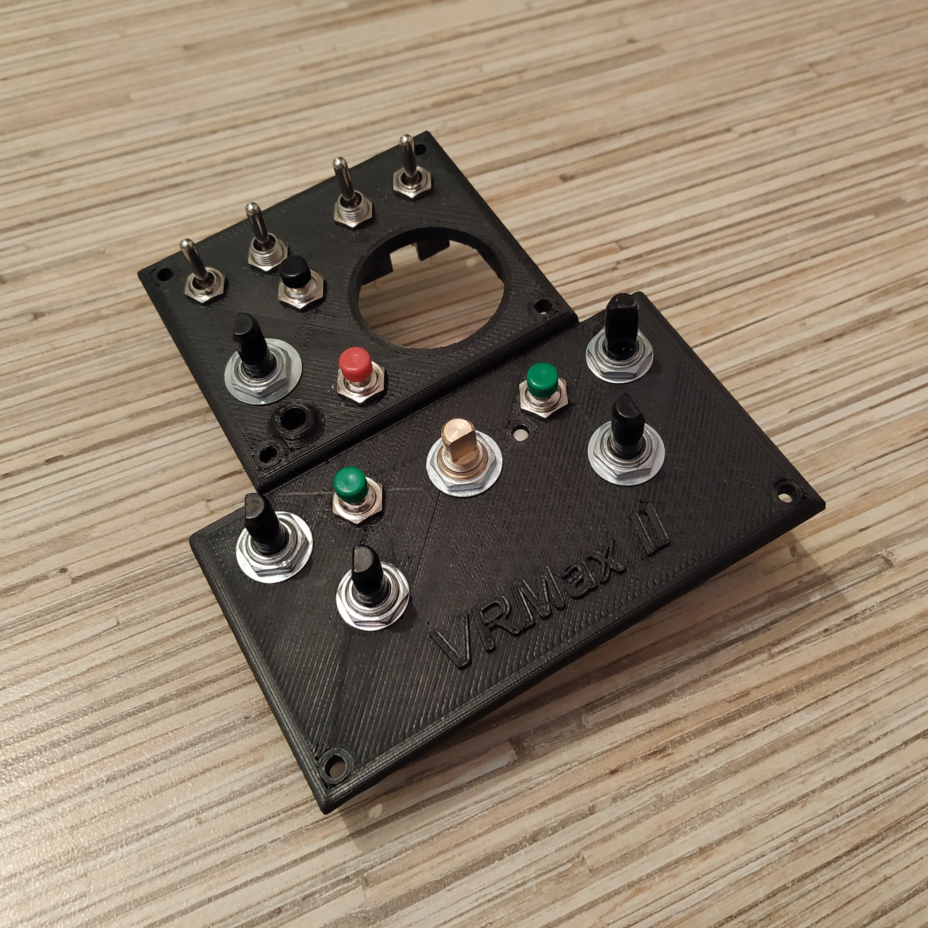
Summary
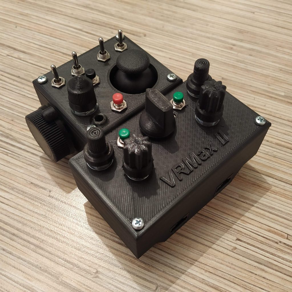
This is an advanced version of the simple pedestal, a universal mouse replacement device for VR. It features a single knob that emulates mousewheel and a ministick to control a cursor – that means you can control any knob in the cockpit no matter how many of them are there. There’s also a radio panel! This device is called VRMax II because it addresses two main problems of VRMax collective head: weight and complexity of
VRMax head is cool, but it’s heavy, thus can’t be used with motion platforms. While it sure has a lot of knobs and covers most of what we need for flying stuff with classic gauges and radio stack, it can’t cover everything we may encounter across various sims and models. That’s why I thought of making a more universal device, that will be simple, functional, and comfortable to use.

Components
4 x MTS-123 or MTS-103 switches
5 x PEC16-4220F-S0024 encoder
4 x PBS-10B2 buttons
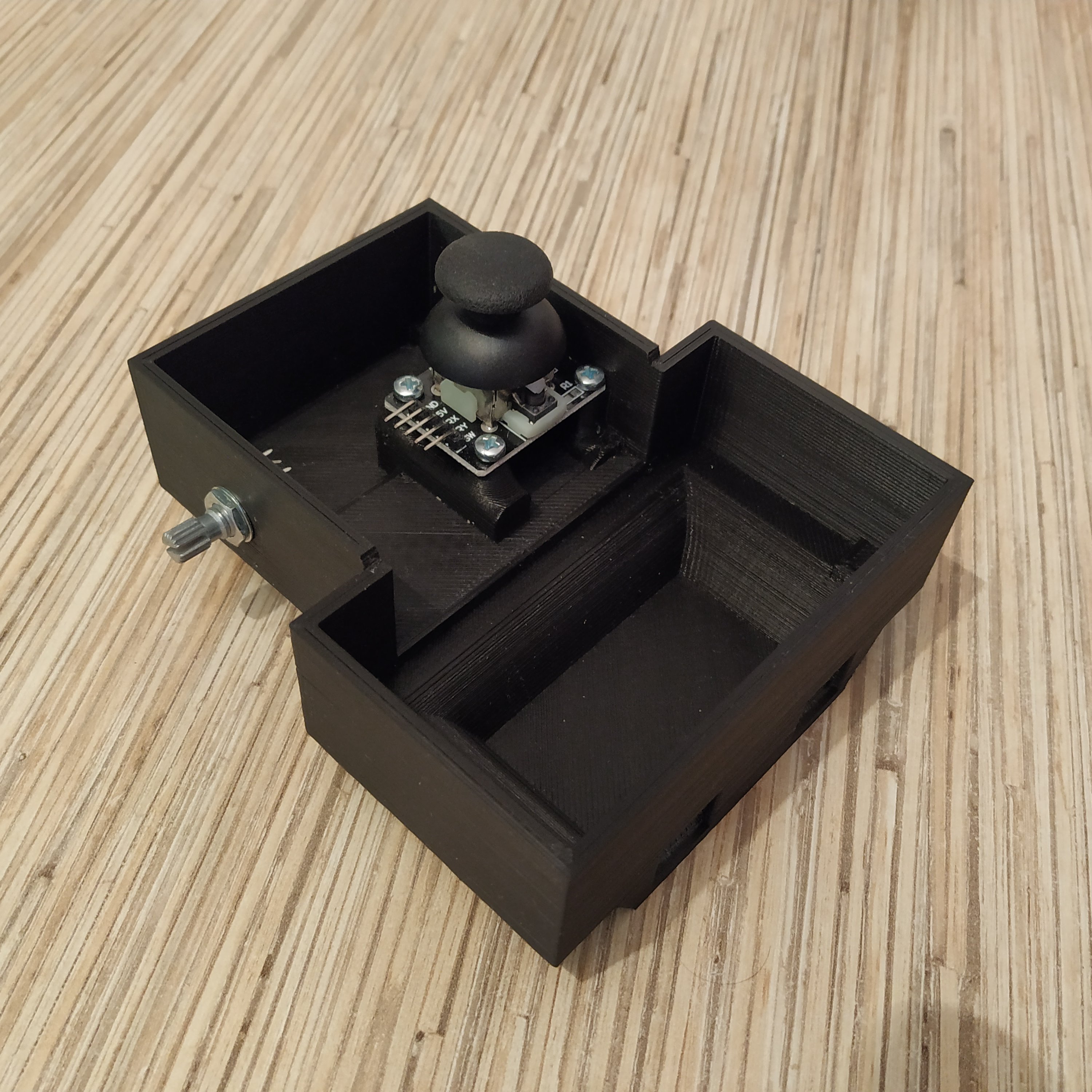
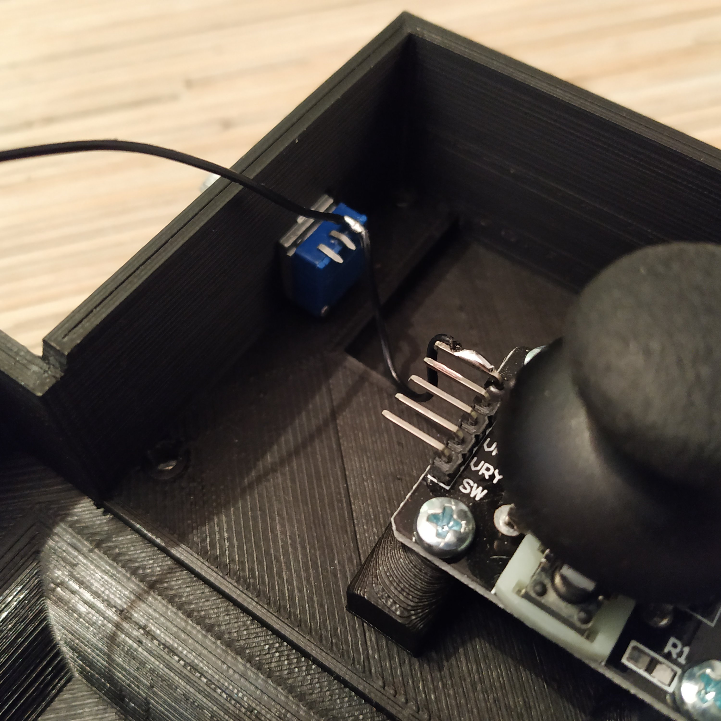
1 x KY-023 ministick board
1 x Bourns PTD901-2015K-B103 10K resistor
1 x RCL371-1-1-1-8 rotary switch
2 x TJ8P8C Ethernet socket
4 x M3x35mm screws and nuts
4 x M3x30mm screws and nuts
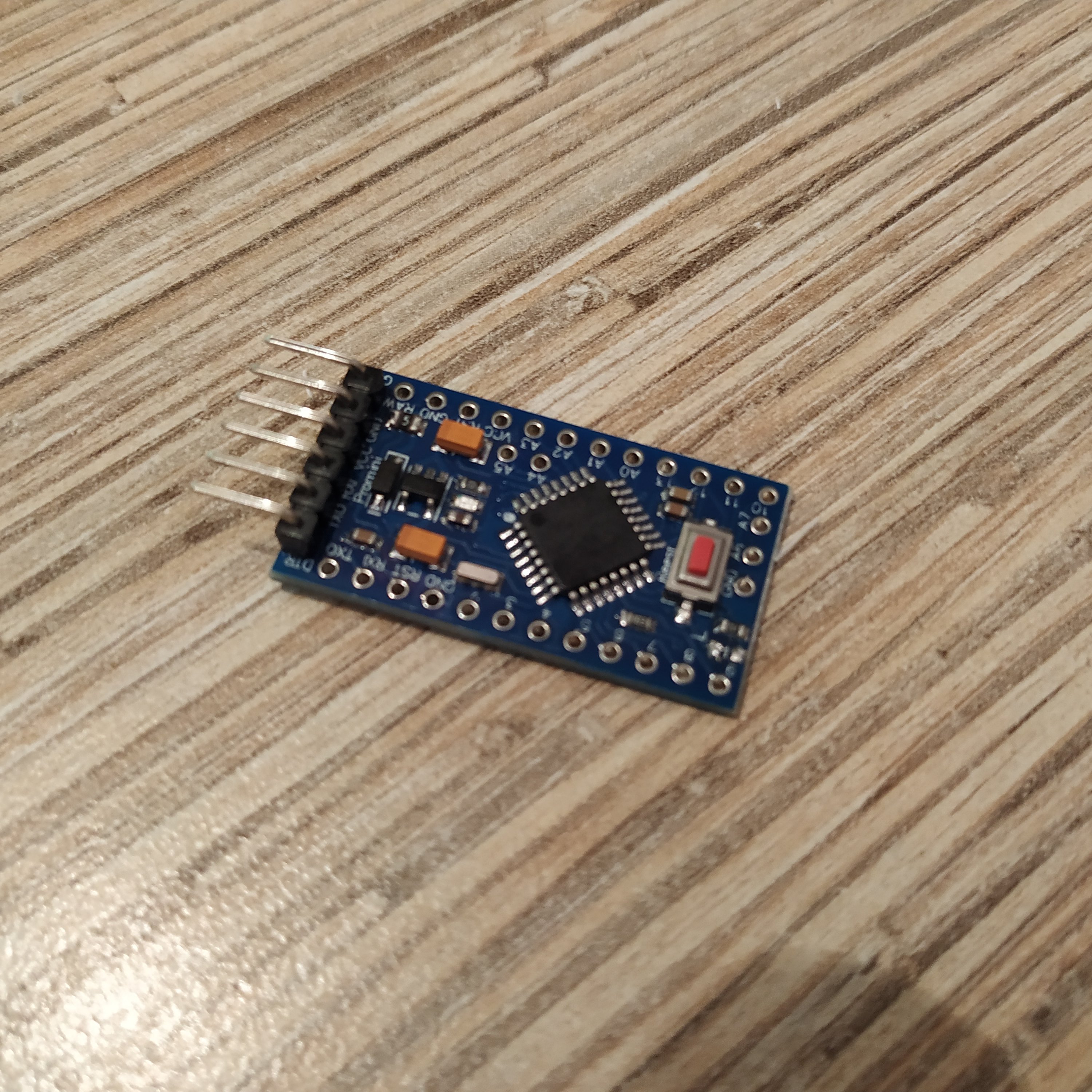
2 x Arduino Pro Mini
Downloads
Assembling manual
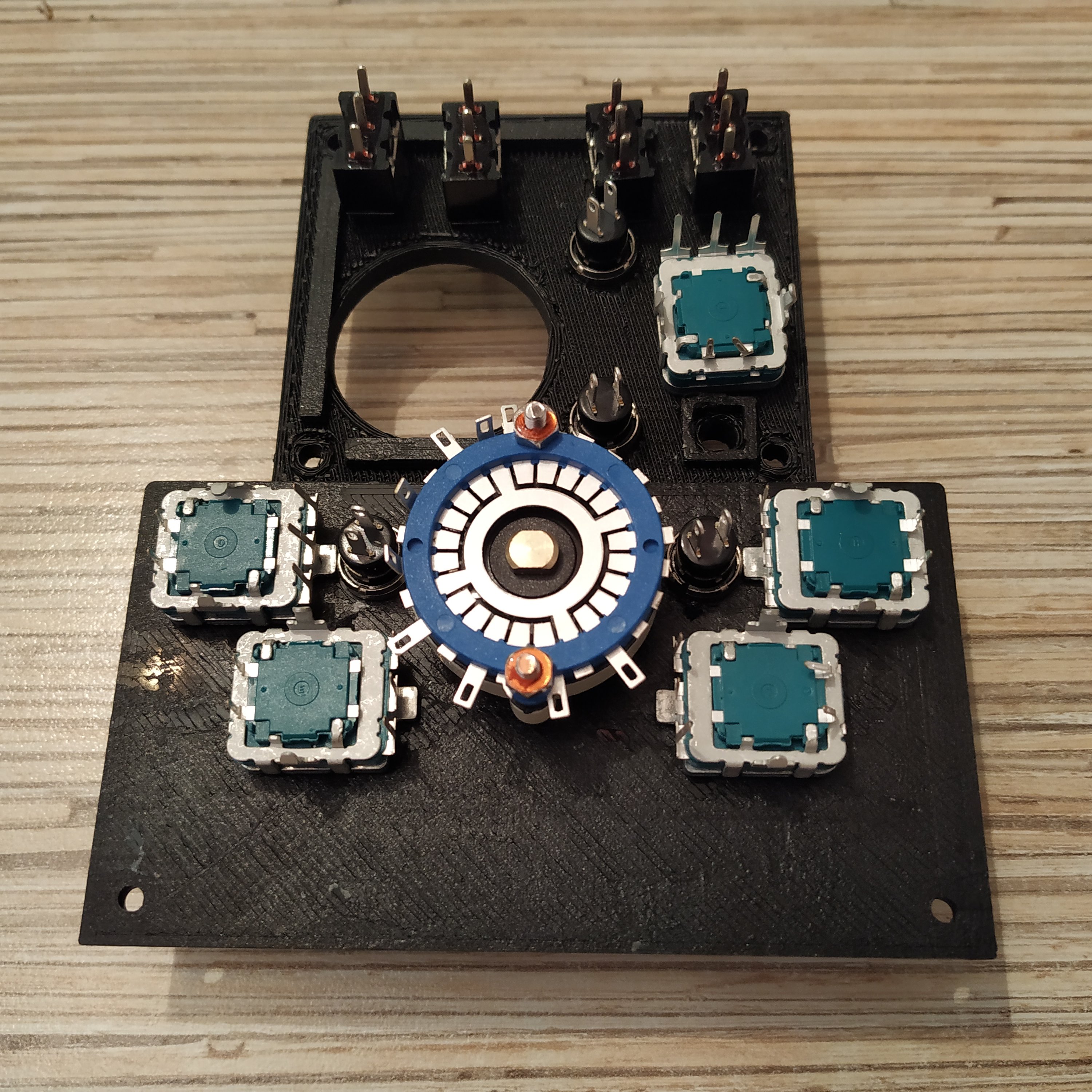
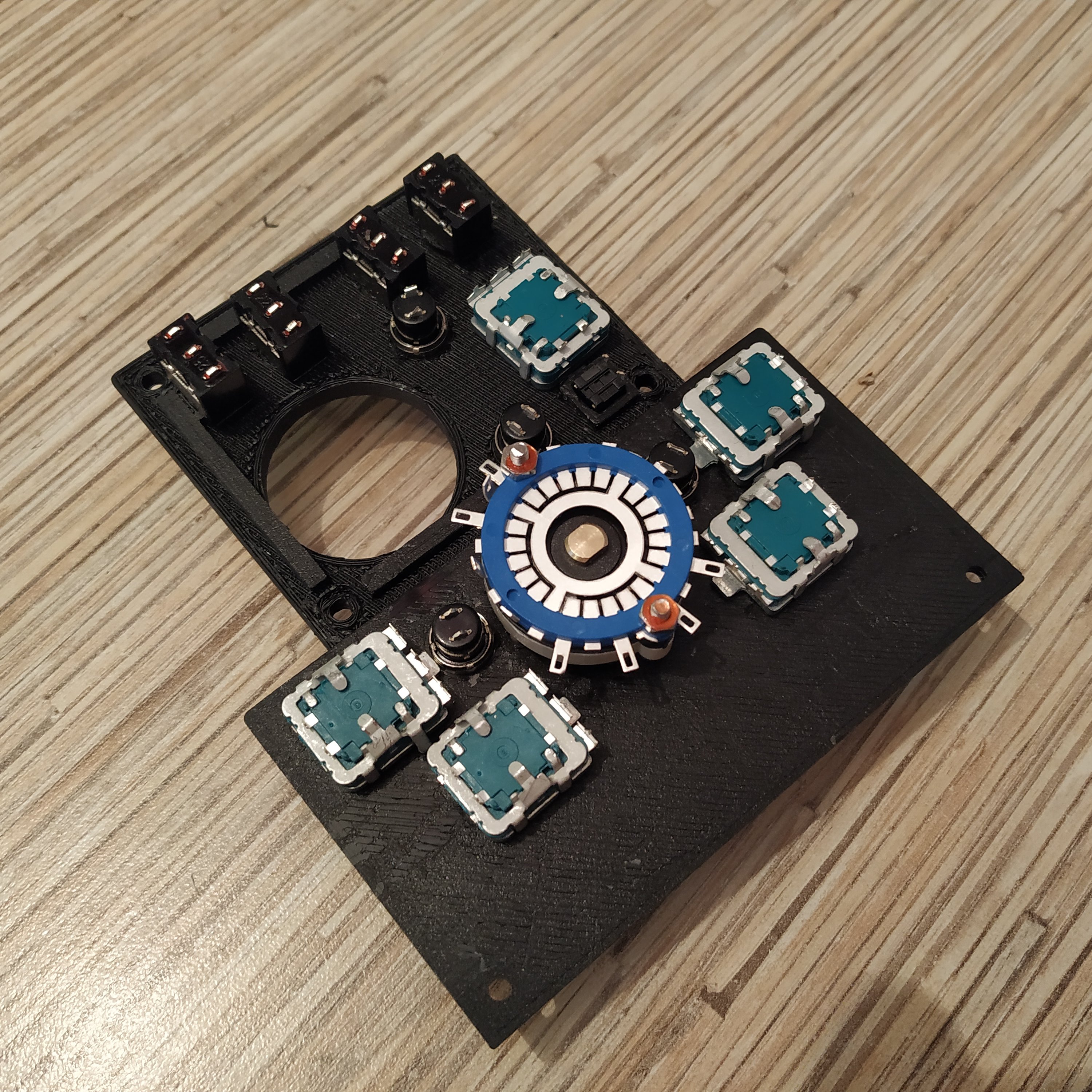
1. Insert switches, encoders and buttons into the panel.
2. Assemble the simple pedestal part of the device by following the corresponding manual. There will be 2 deviations: you will need to make an I2C (pins A4 and A5) tie to connect to the other board, and you will need to connect RST pins of Arduinos together with a wire.
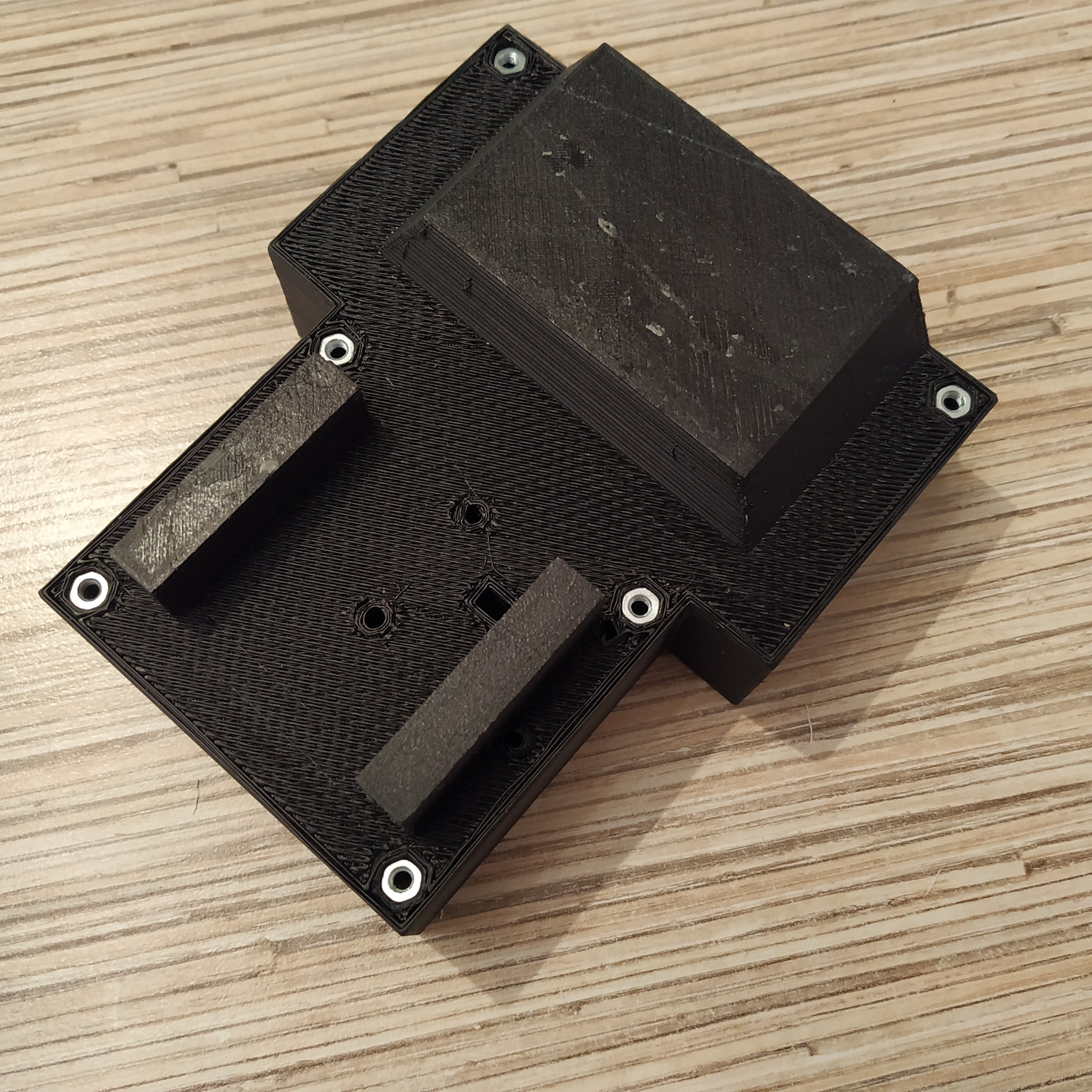

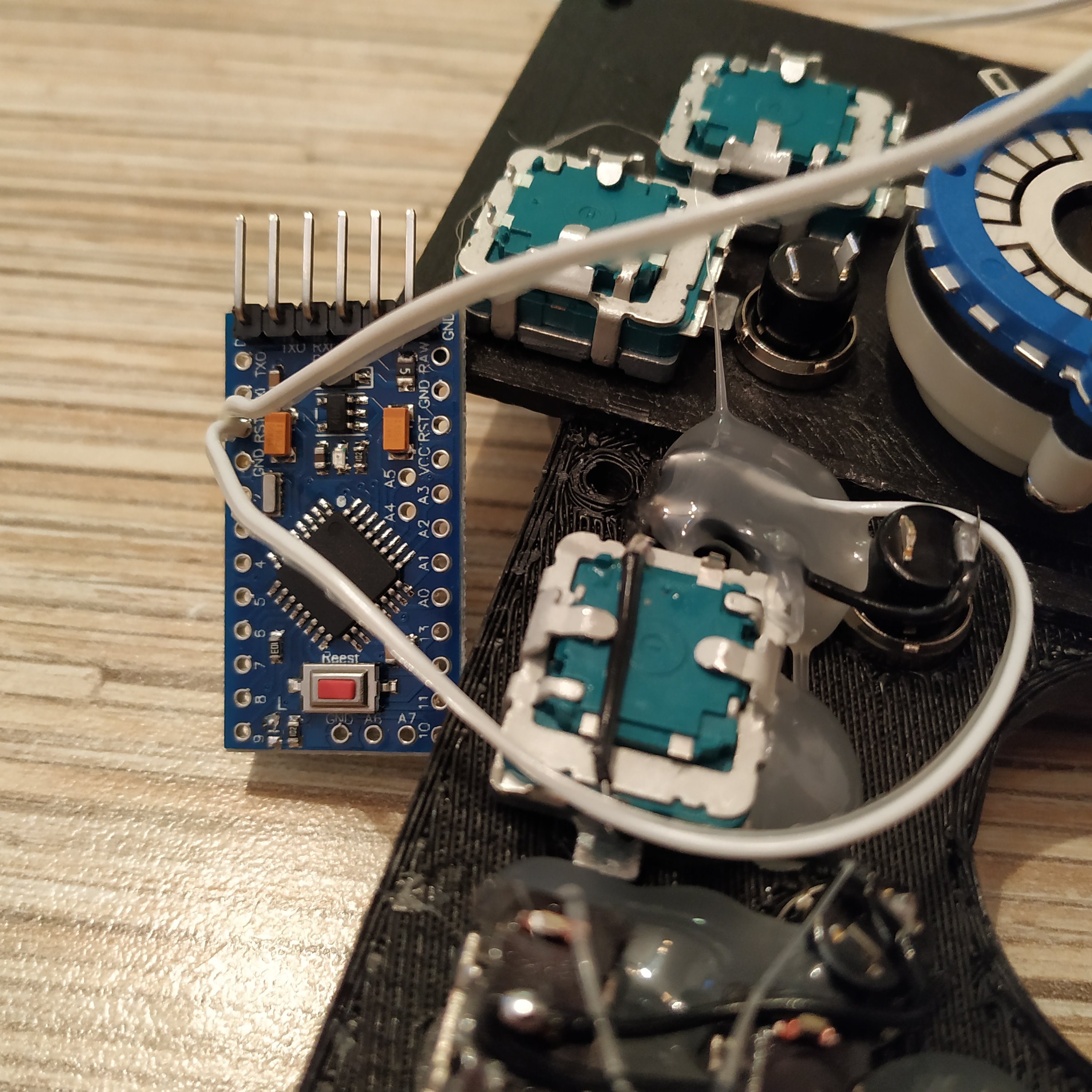
A small difference: we will be connecting RST button wire to both boards, so make it longer or make a tie as shown on the pic above.

3. Check that the simple pedestal part works by flashing it with its firmware. Make sure to use controller A firmware from VRMaxII pedestal folder.
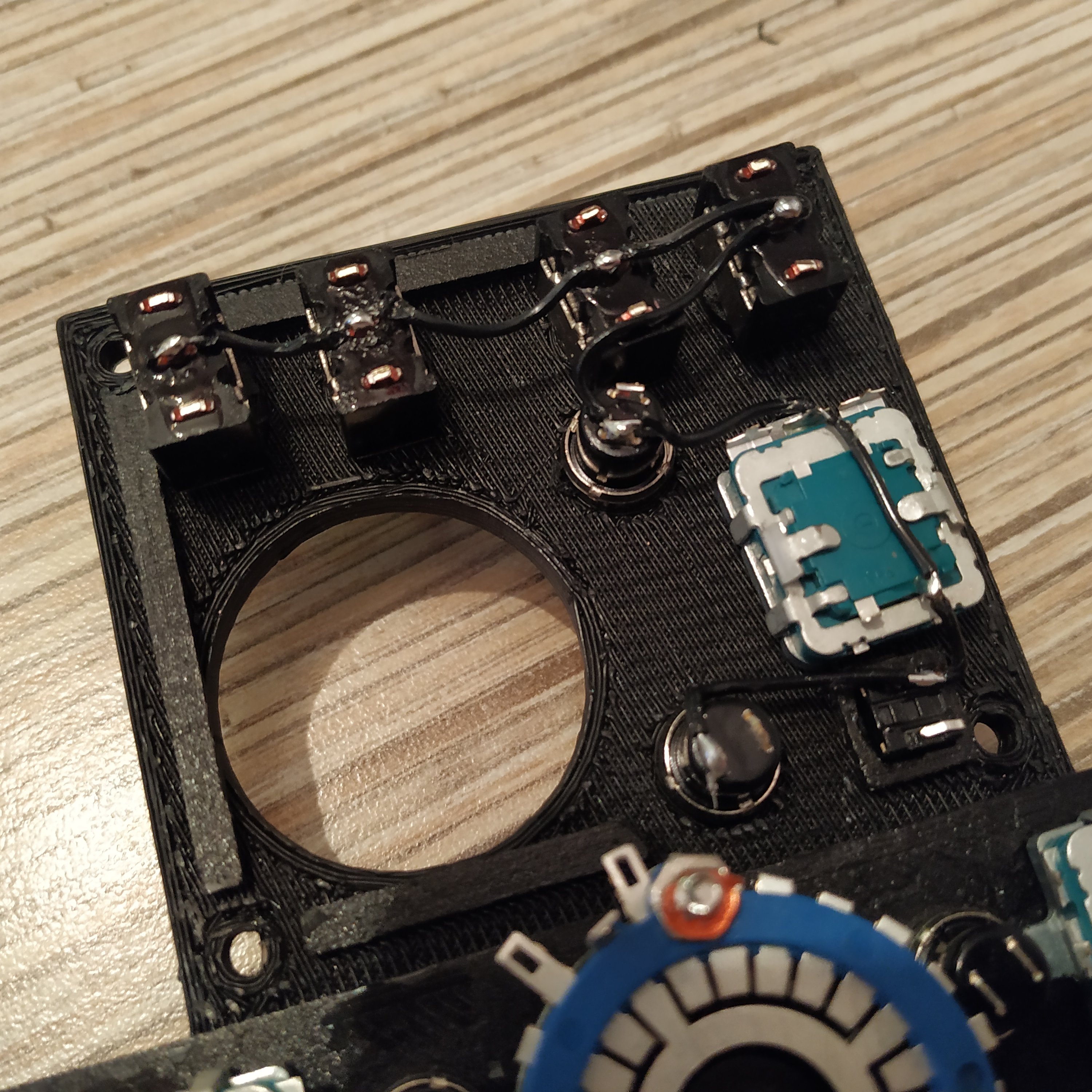
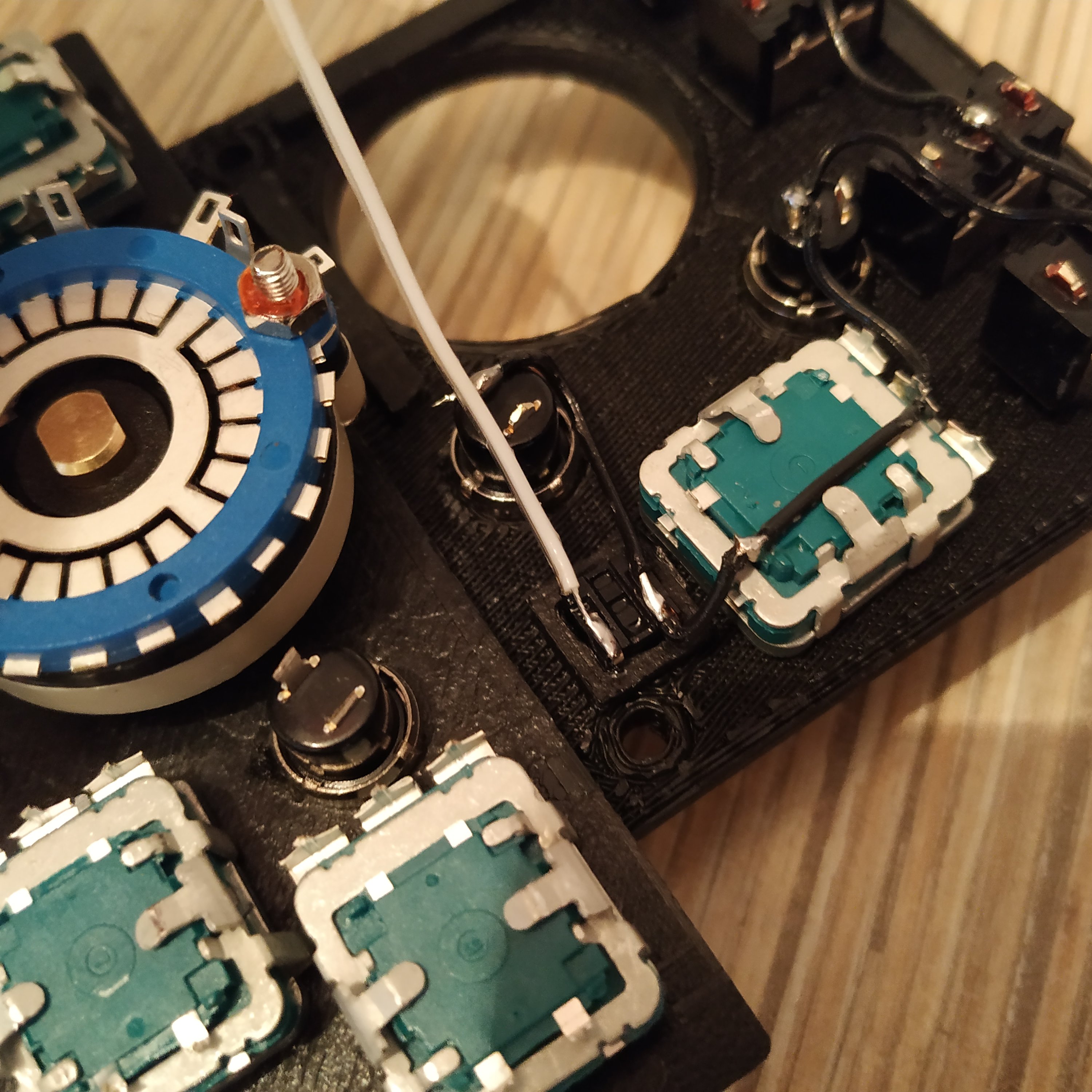
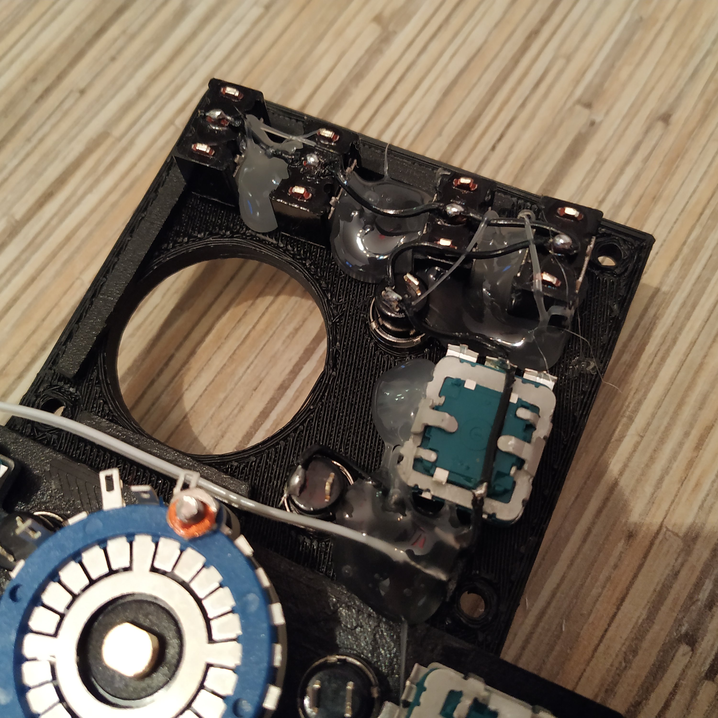
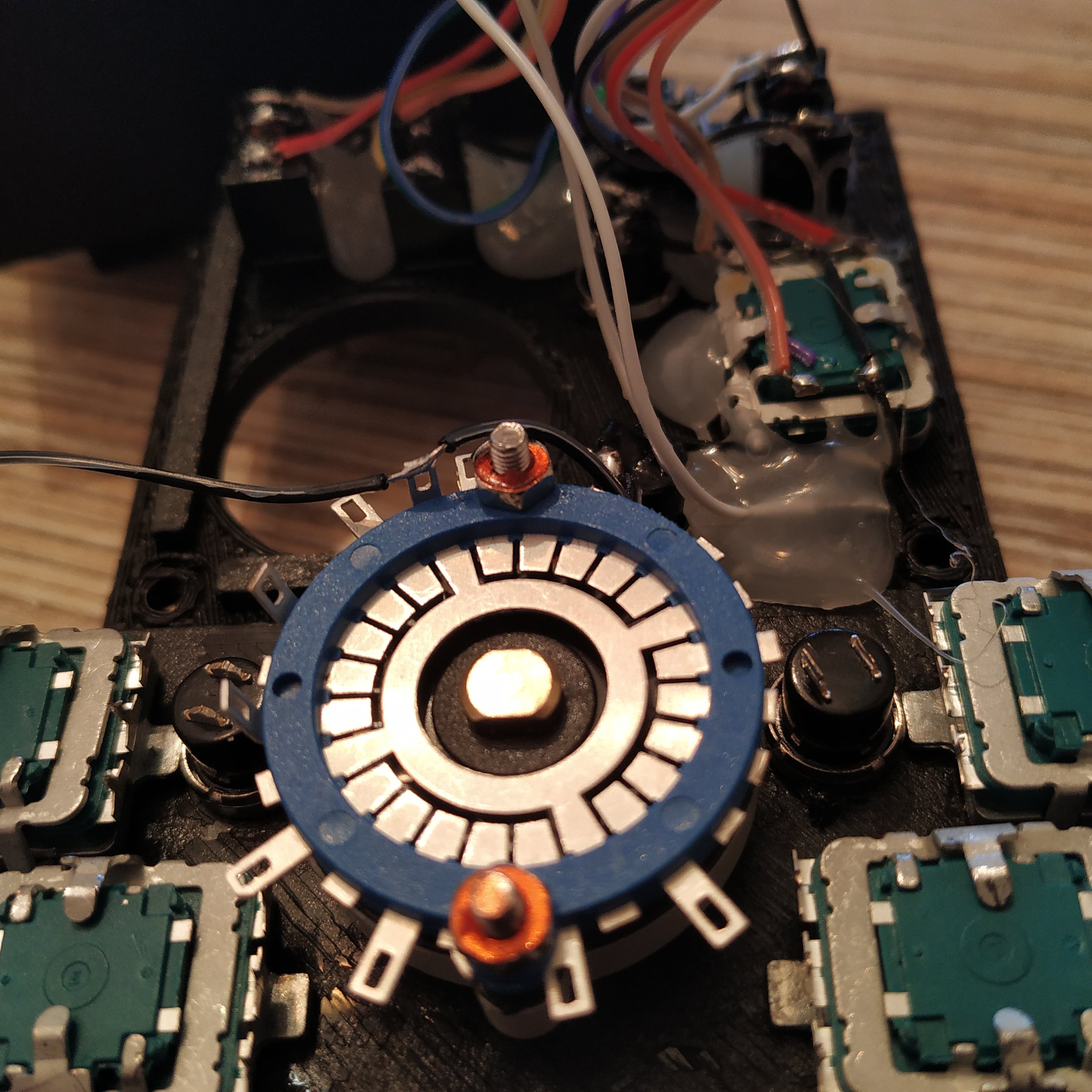
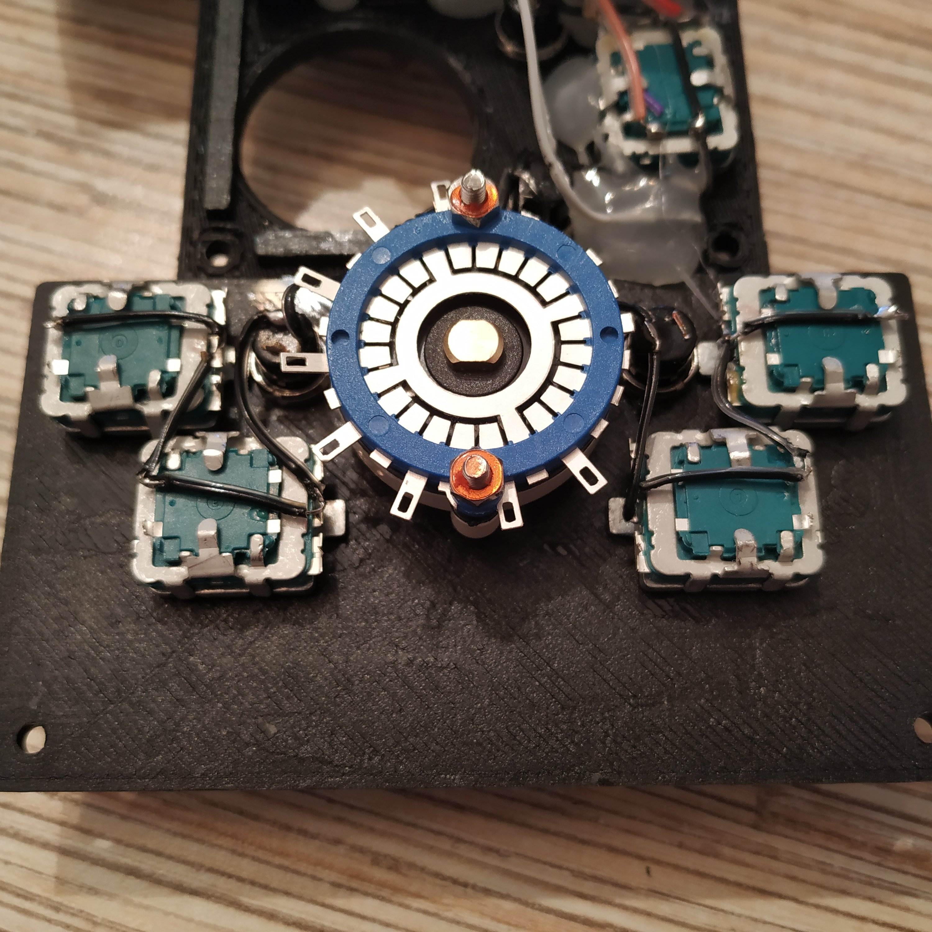
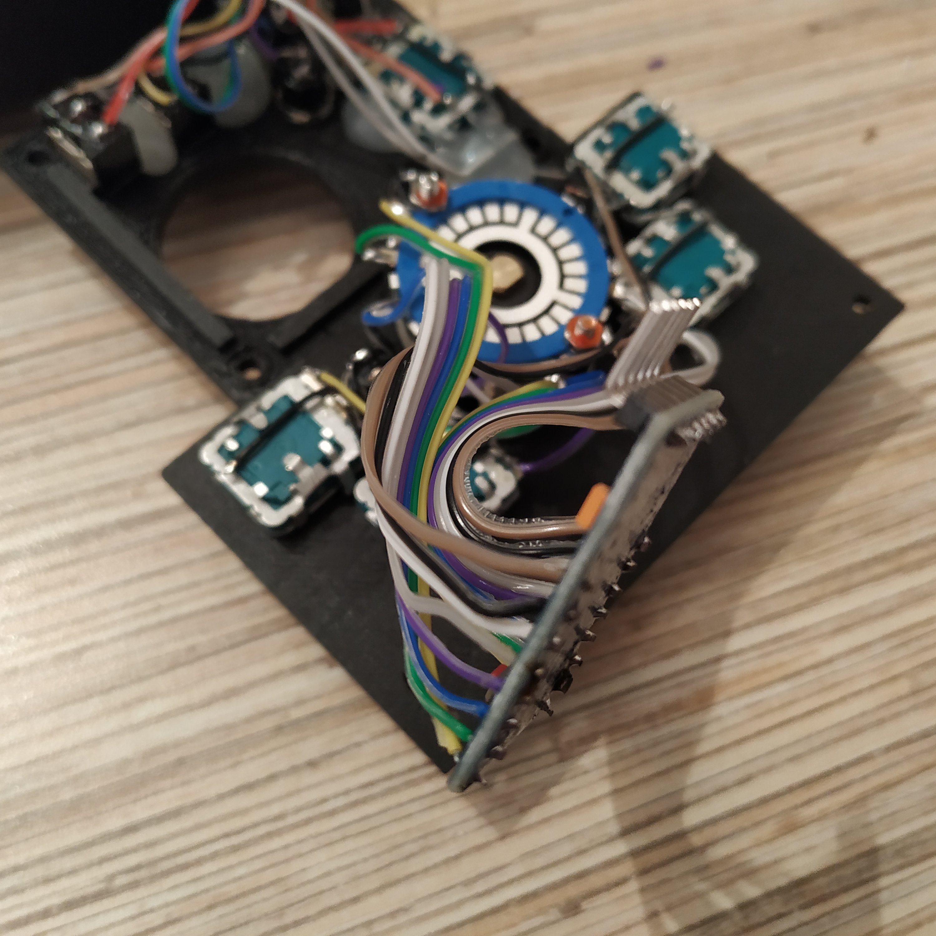
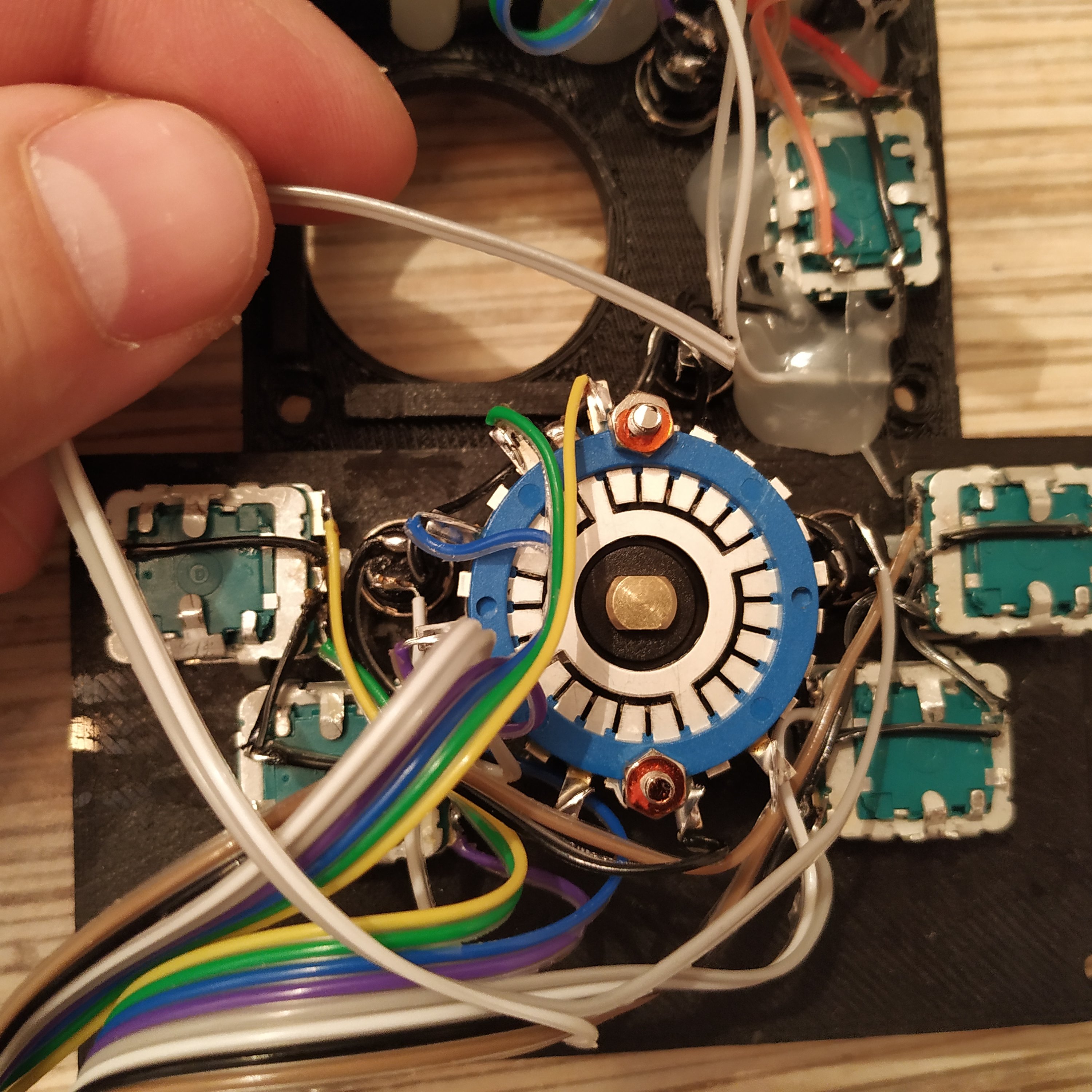
4. Solder the ground wite to the radio panel part. The lid of the rotary switch is removed so you can see GND pins (4 pins connected to the central ring).
5. Attach
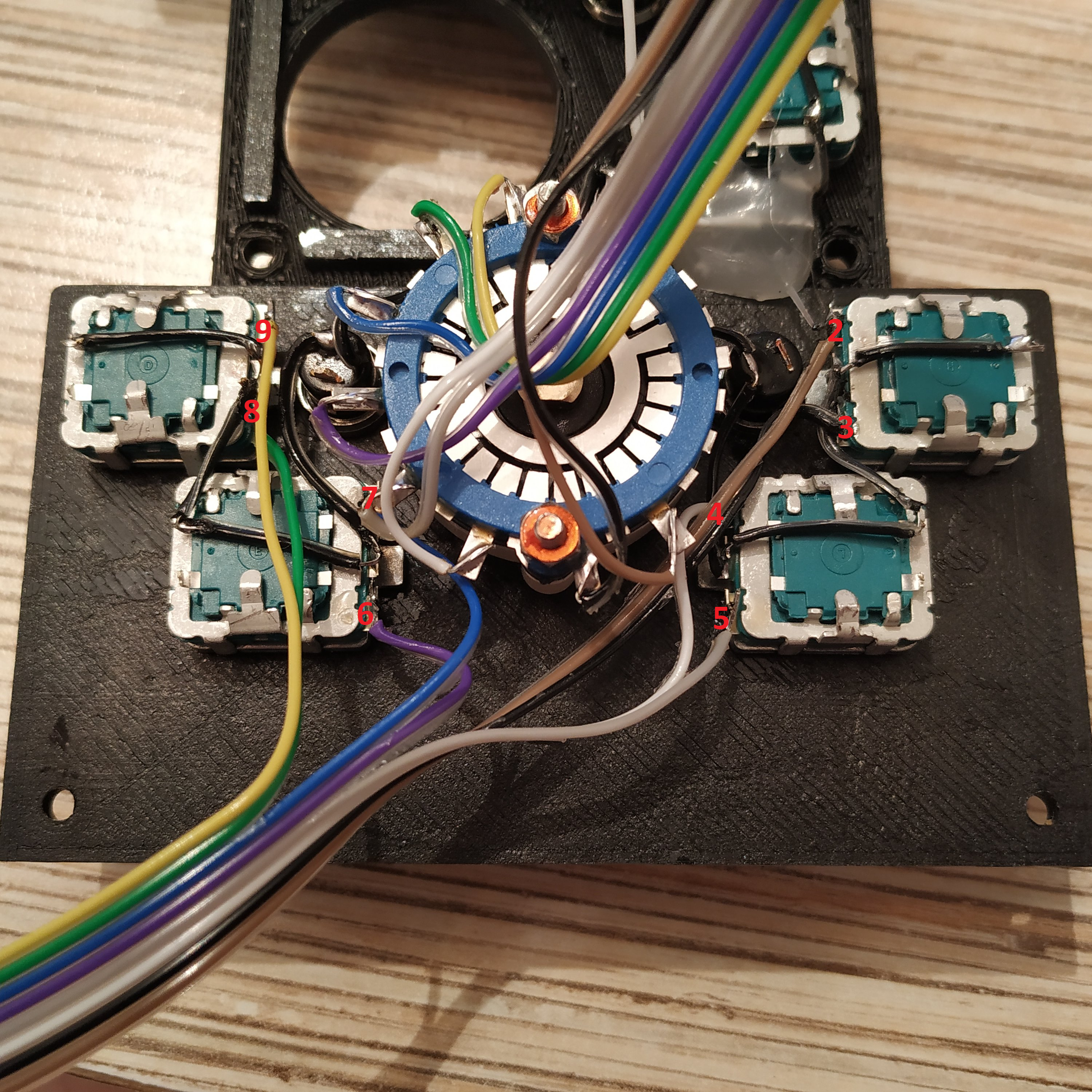
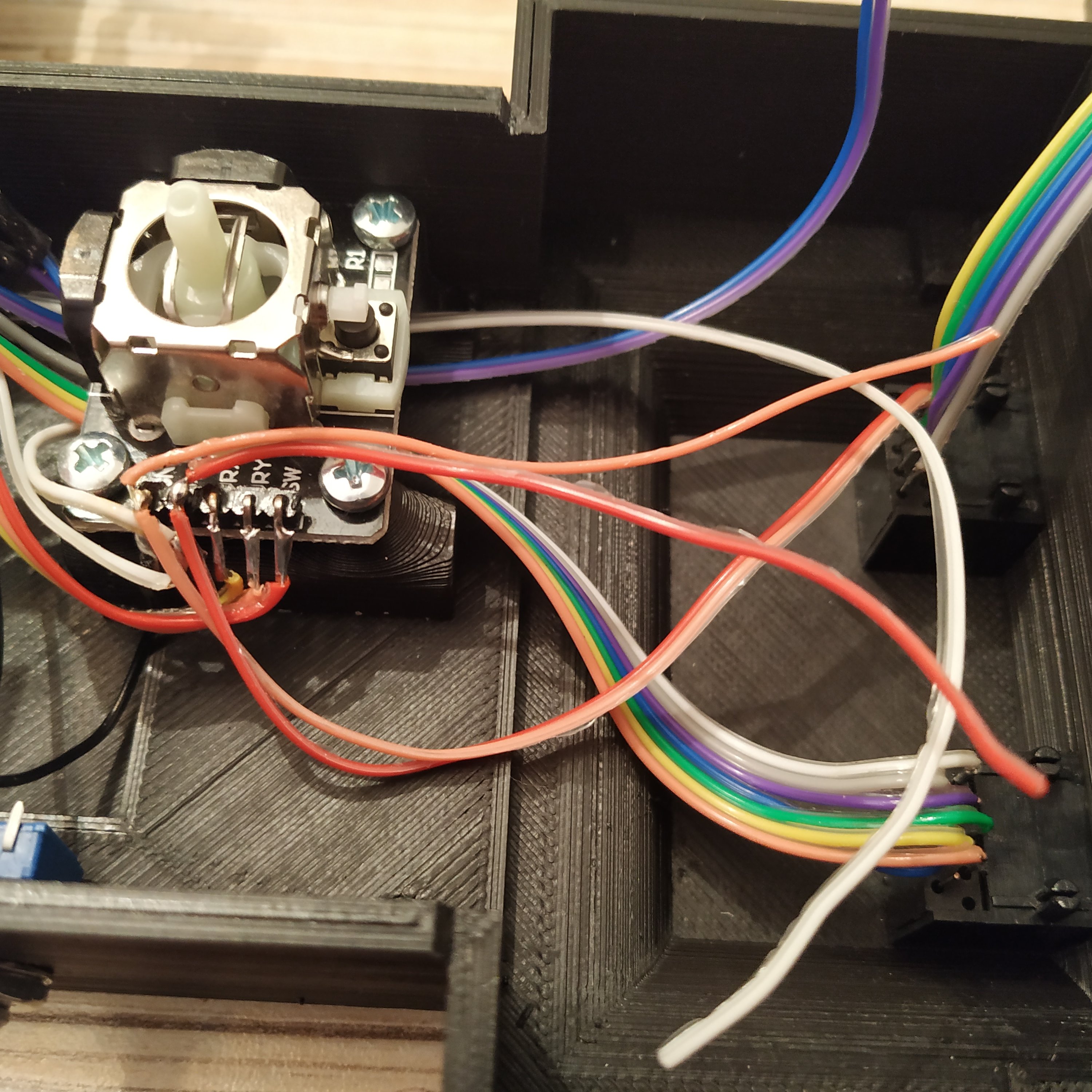
6. Attach another 8-wire cable to encoders, from right to left, as shown in the picture below. Red numbers show Arduino pins:
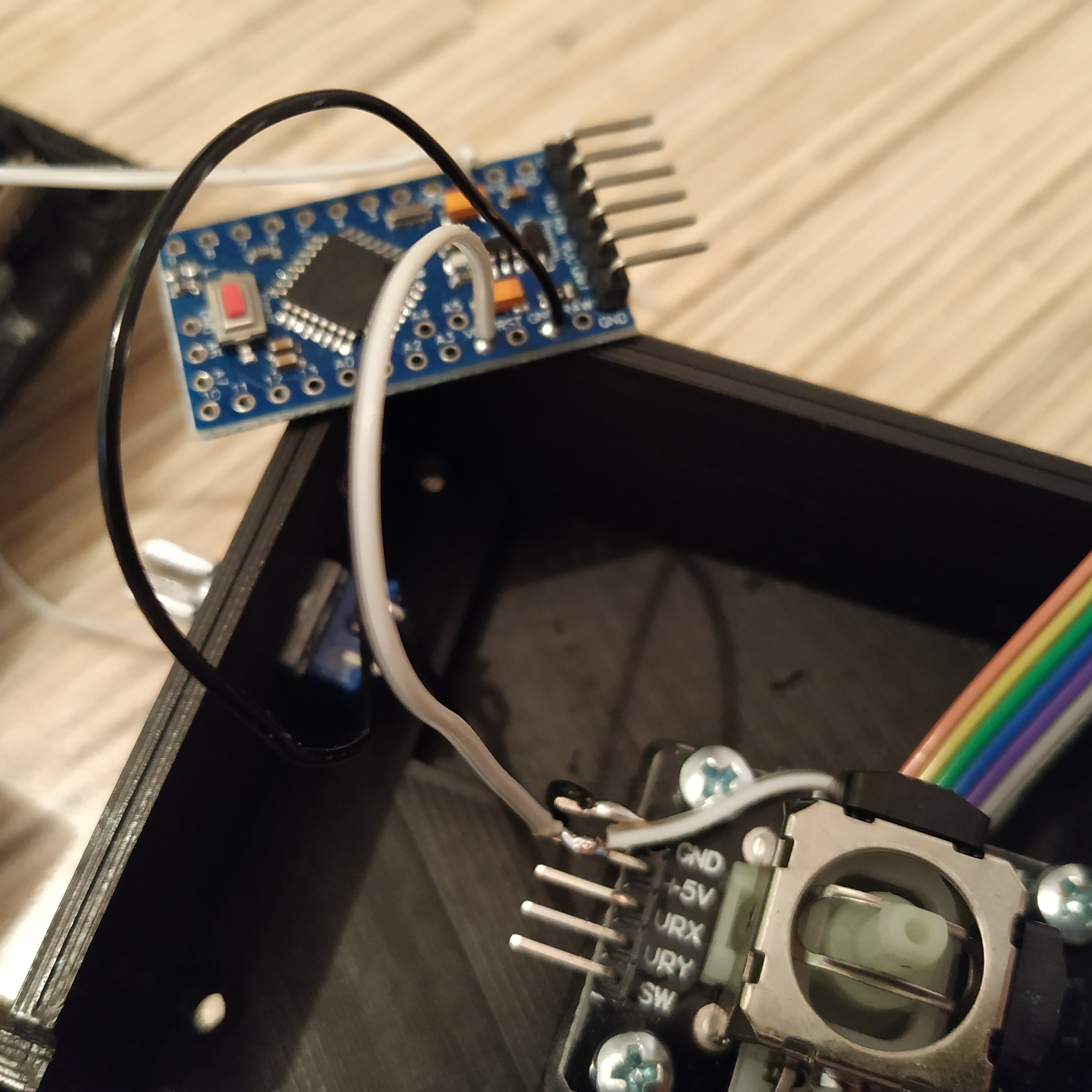
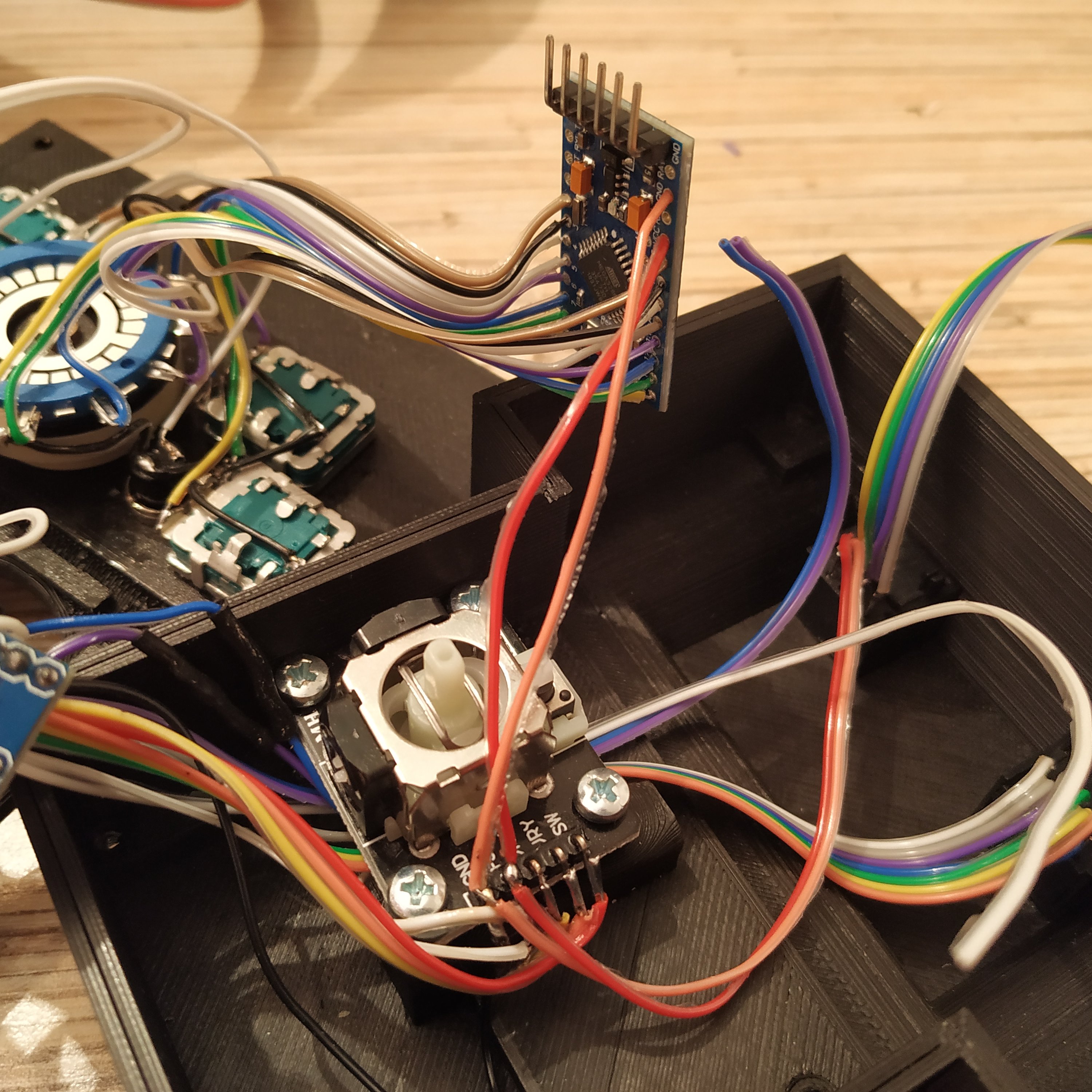
7. Solder an UART header to another Arduino board and remove LED on pin 13.
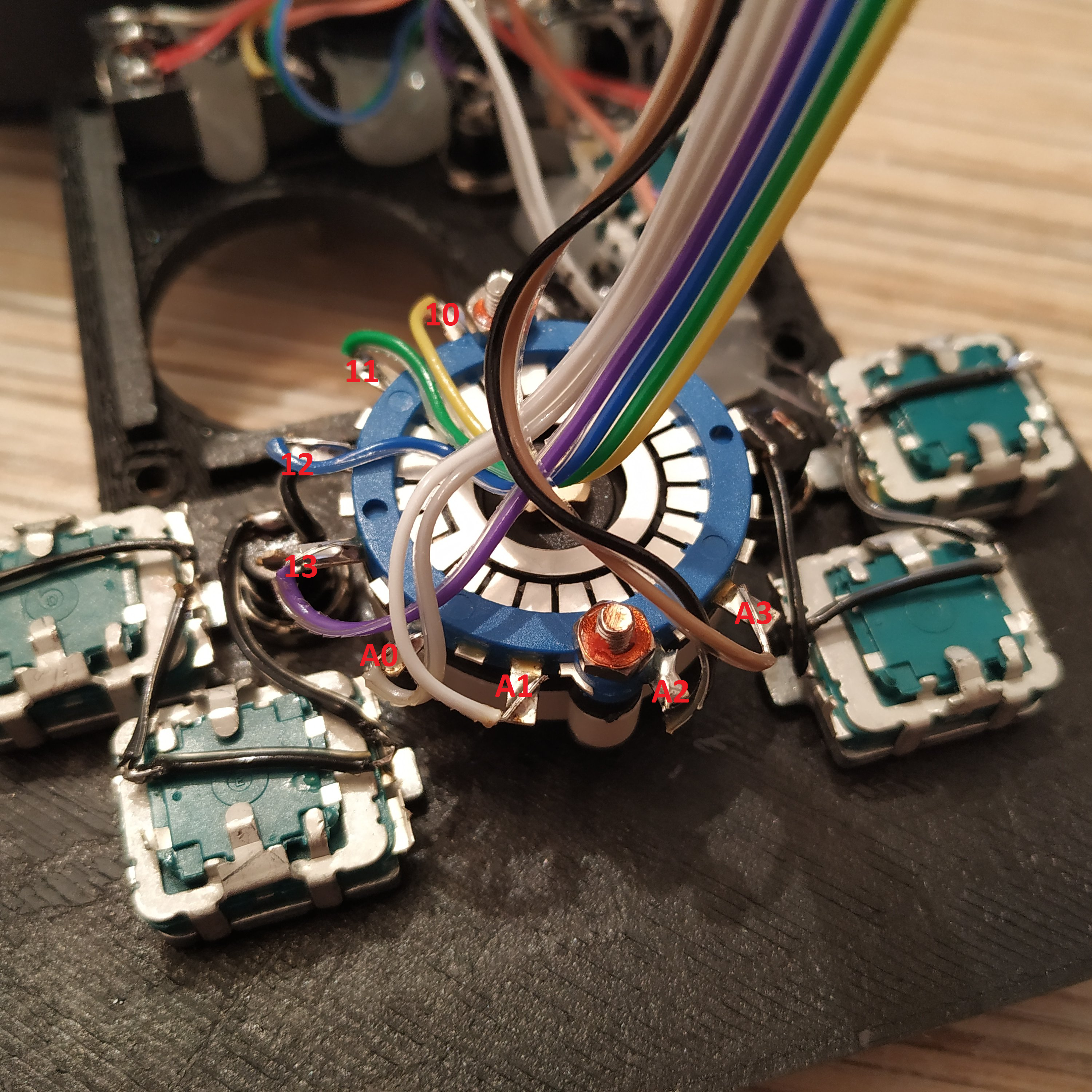
8. Solder encoders and rotary switch cable according to red pin numbers show in their corresponding pictures.
9. Connect two radio panel buttons to pins A1 and A2 of the simple pedestal Arduino board, right one to A1, left one to A2.
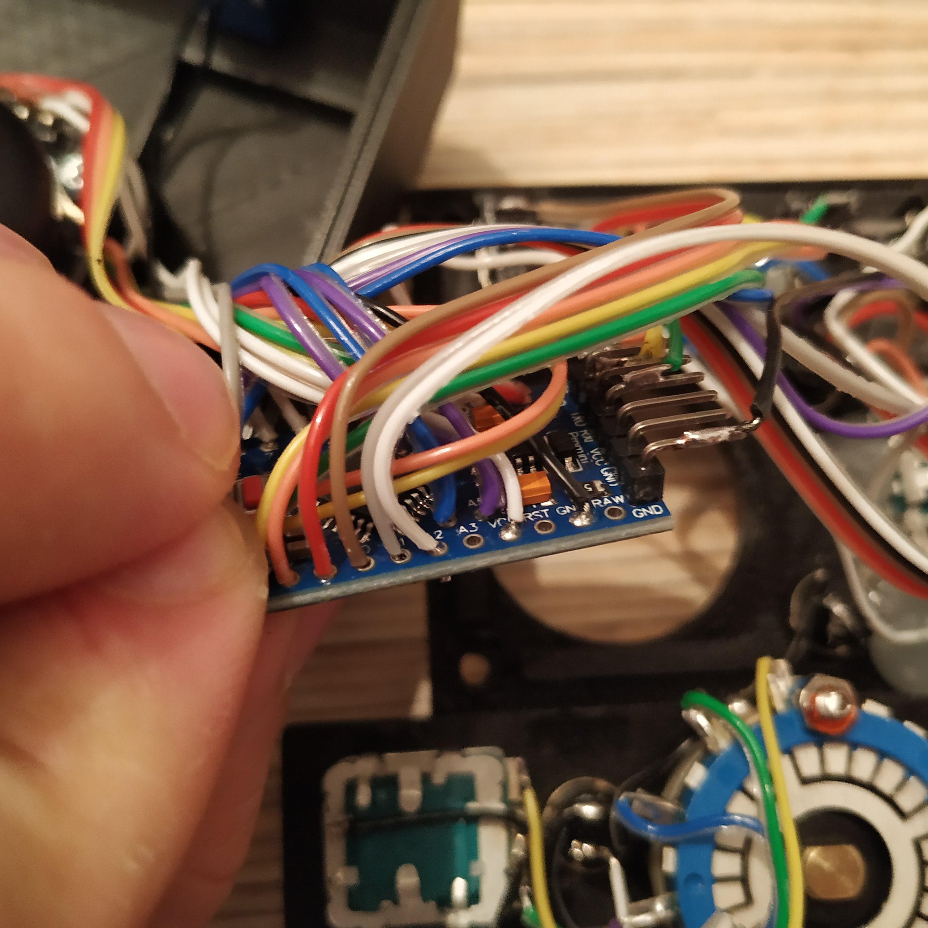
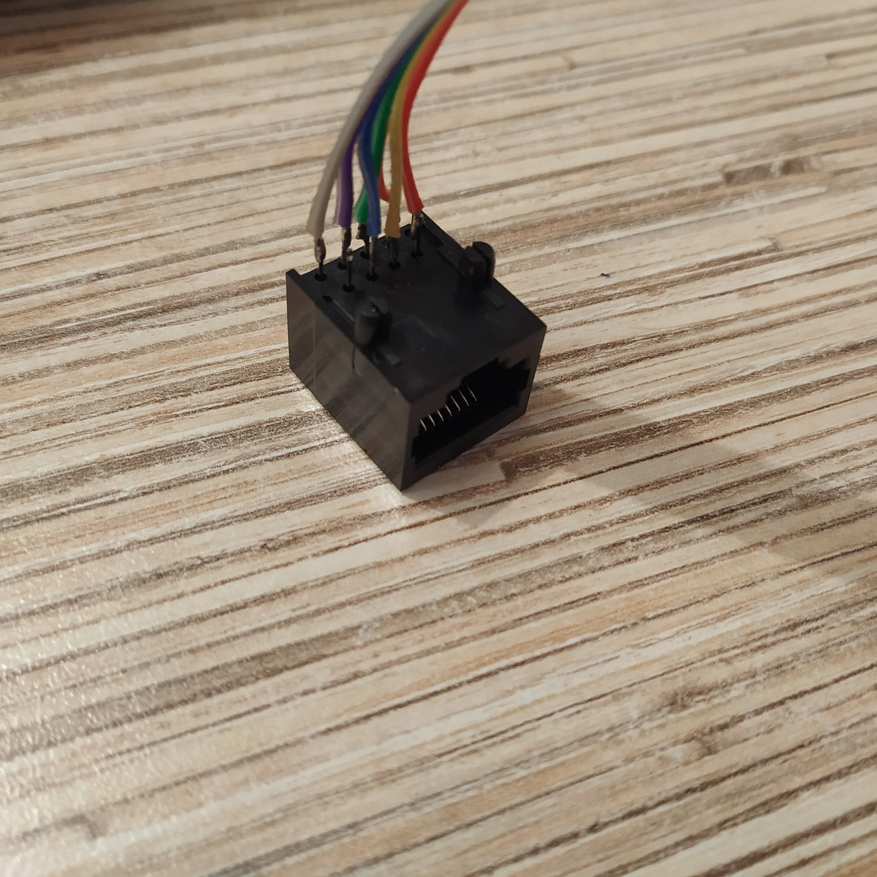
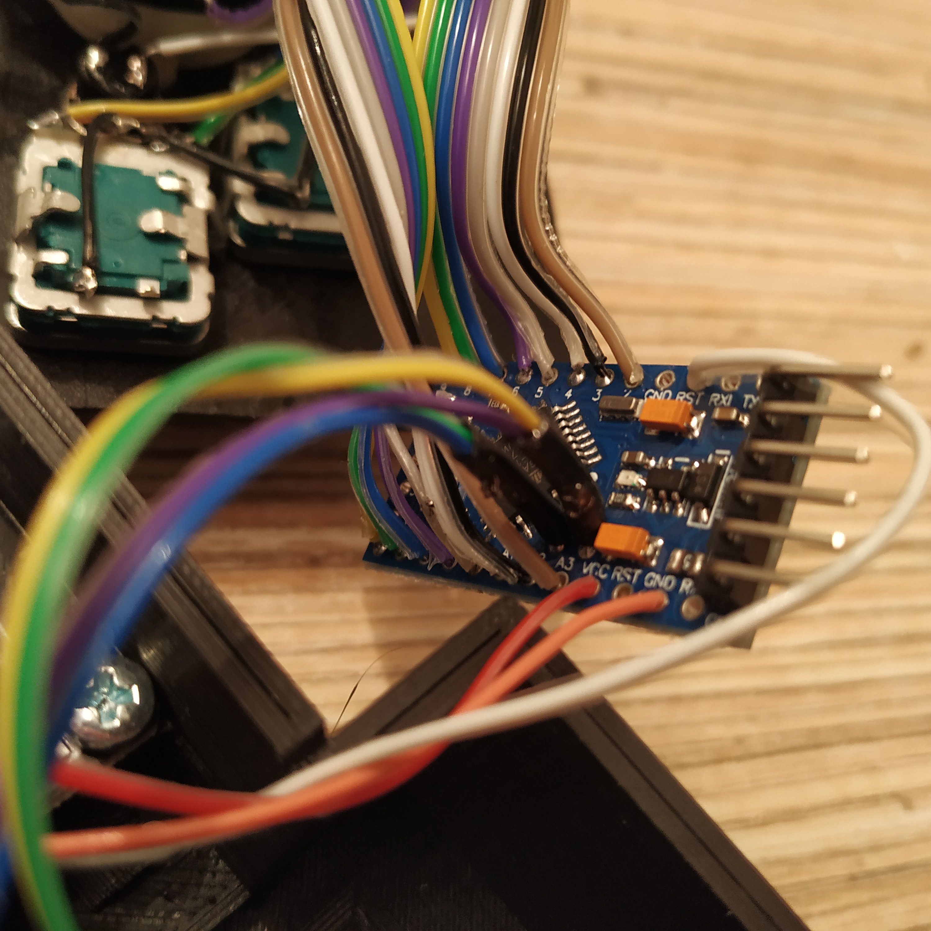
10. Solder a 7-wire cable to another ethernet socket, starting from pin 1. IMPORTANT: last 3 wires go to Rx, Tx, and DTR pins of the 2nd board!
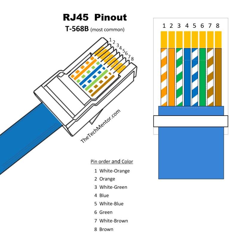
- SOCKET PIN 1 (WHITE-ORANGE wire of Ethernet cable) -> 5V
- SOCKET PIN 2 (ORANGE wire of Ethernet cable) -> GND
- SOCKET PIN 3 (WHITE-GREEN wire of Ethernet cable) -> SCL
- SOCKET PIN 4 (BLUE wire of Ethernet cable) -> SDA
- SOCKET PIN 5 (WHITE-BLUE wire of Ethernet cable) -> PRO MINI #2 Rx
- SOCKET PIN 6 (GREEN wire of Ethernet cable) -> PRO MINI #2 Tx
- SOCKET PIN 7 (WHITE-BROWN wire of Ethernet cable) -> PRO MINI #2 DTR
11. Solder Connect 5V and GND wires of the Ethernet socket to KY-023 board and then to the radio panel Pro Mini board.
12. Solder RST wire from the 1st board to the radio panel one.
13. Make a tie of SDA (pin A4) and SCL (pin A5) wires from the simple pedestal board and connect them to the radio panel one. Use some shrink tube to hold wires together.
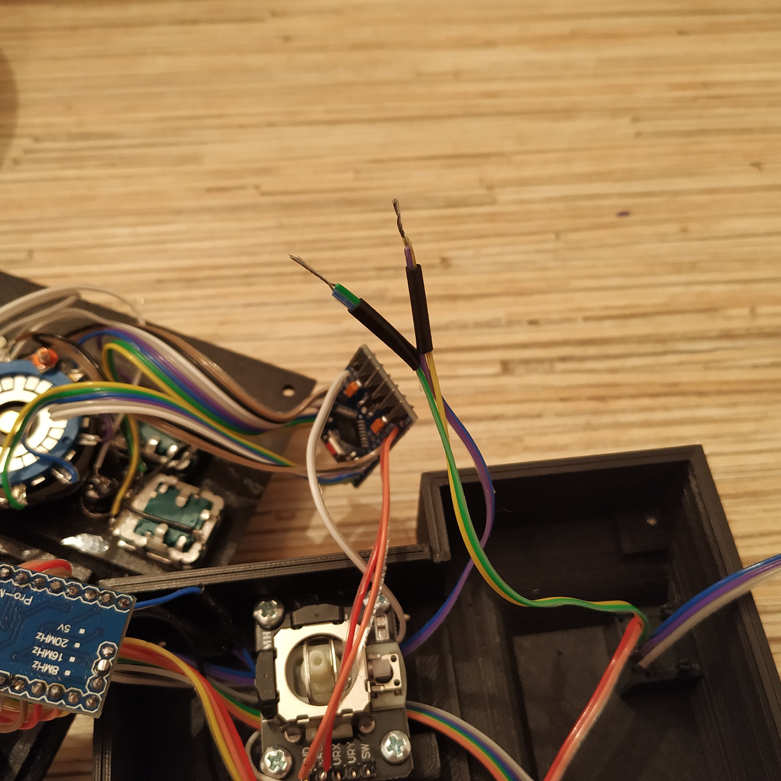
14. Connect wires 5,6 and 7 of the Ethernet socket to RX, TX and DTR pins on UART header of the radio panel Arduino board.

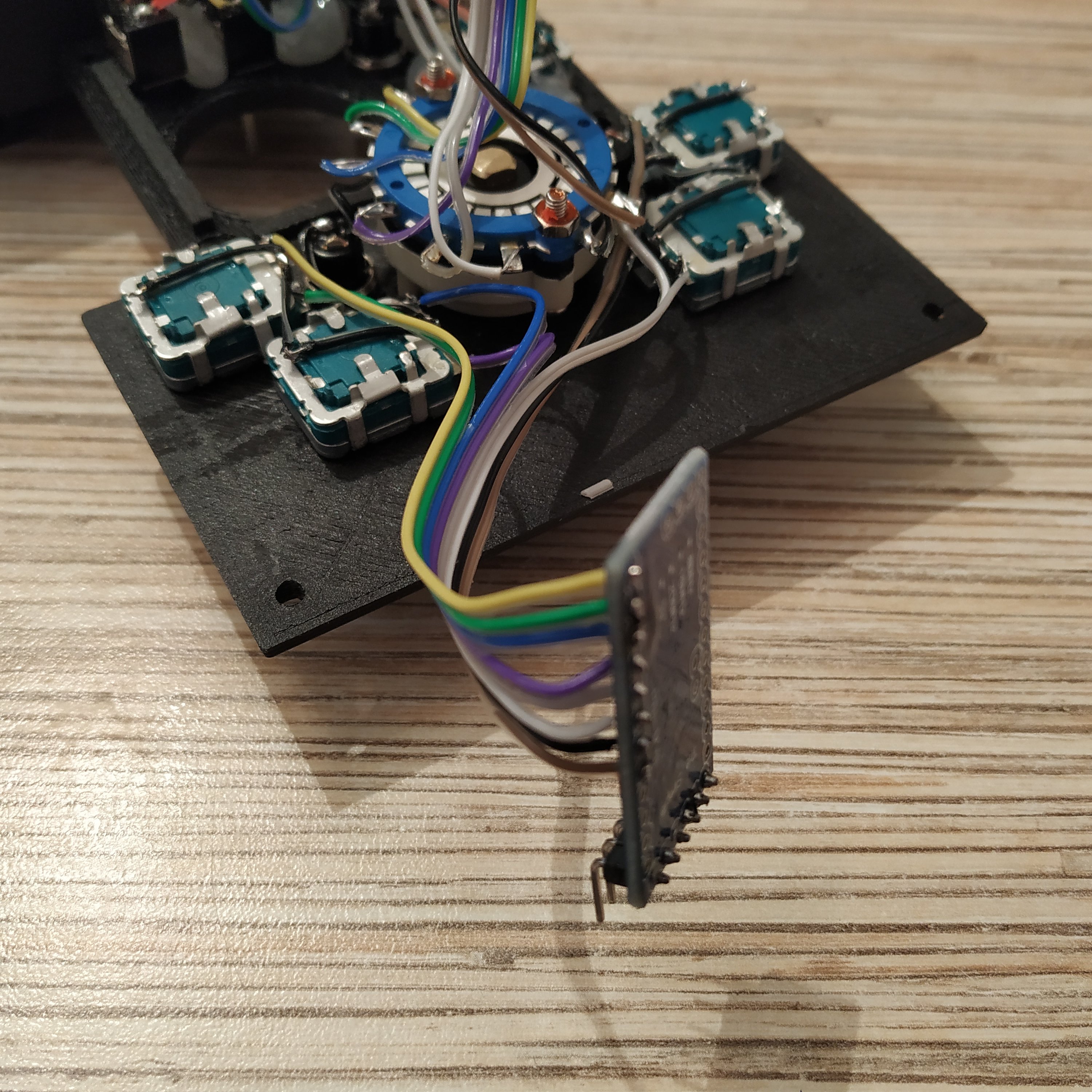
15. Do some cable management, close the lid and try if everything works! To do it, flash the simple pedestal part of the device (LEFT SOCKET) with vrmaxII_pedestal_a.ino and the radio panel part (RIGHT SOCKET) with vrmaxII_pedestal_b.ino firmware.
Uncomment
#define VRMAXII_PEDESTAL
in “device definitions” tab of master controller firmware.
Open HTML5 gamepad tester and check that all buttons work in all modes. If moluse pointer moves when you connect the device, adjust
| #define X_CENTER #define Y_CENTER |
values under the configuration tab to suit your hardware (Serial.print these values under the ga_vrmaxii_pedestal tab to check them)
Check that the pointer works good, and adjust the sensitivity setting to your liking:
#define MINISTICK_SENSITIVITY_LOW 5
#define MINISTICK_SENSITIVITY_HIGH 15
You may want something like low 1 and high 5 if the collective is your only device, and higher values if the board has a lot of stuff connected to it. Reflash the board again and check if pointer speed satisfies you, repeat the process if necessary.
16. Finish the device by pouring some hot glue onto Ethernet sockets and close the lid. Put knob caps on.
Congratulations, your pedestal is finished!
Thank you very much for the great project !!!
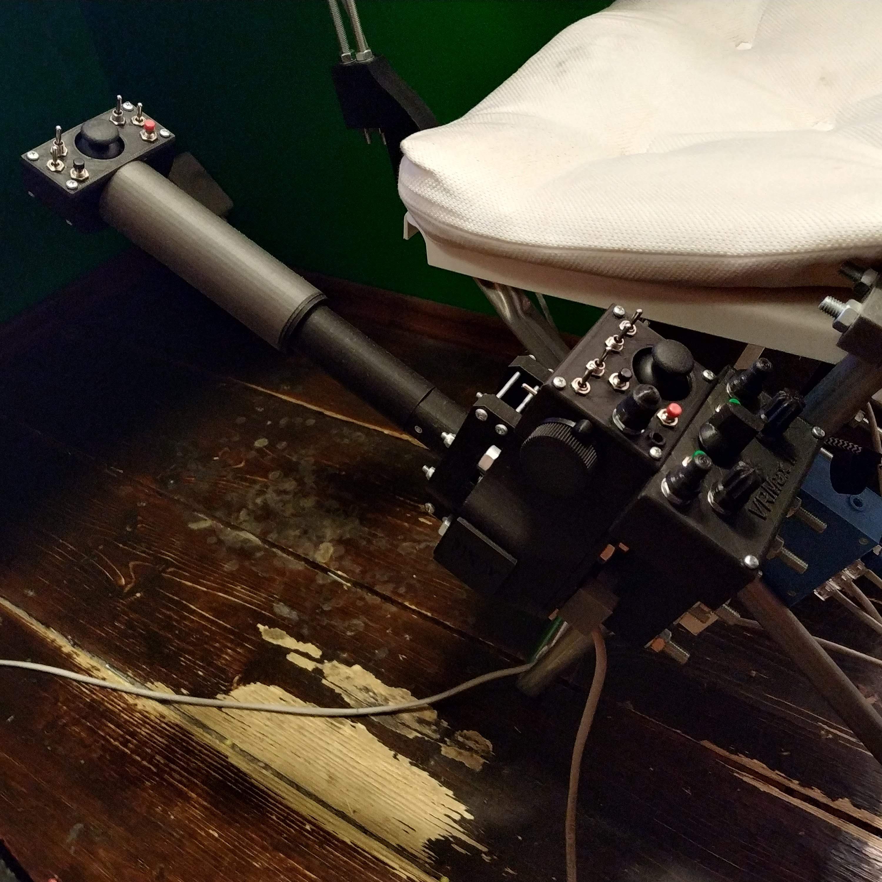
I build a single throttle lever body for integrated heads with the Compact collective head
and the VRMax II pedestal.
The encoders in the radio section output values via the serial interface. How can I adjust the COM frequencies in the fs2020 or x-plane and how can the 8-pole rotary switch be evaluated there ?
many Greetings from Kiel
Juergen
Hi Jurgen! Thanks for your kind words.
Encoders work as buttons (each encoder presses the joystick button when turned to the right and another one when turned to the left). The rotary switch works as a modifier – depending on its position every encoder will press a different set of joystick buttons. The rotary switch itself is not displayed as joystick buttons. Have you built the master controller yet?