Important notice
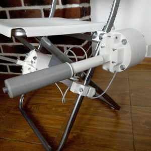
I don’t think there’s any point in making this one anymore, as the single-engine lever with head support is as smooth in movements as this one, yet collective switch panels (heads) allow for additional functionality, like idle-stop support. This one will probably be used later for RC FPV flying =)
Components
1 x 250x10x10mm aluminum square pipe
1 x 20×10 aluminum rectangular pipe for chair mounting (the mount for the IKEA GUNDE chair is included)
1 x SS495A hall sensor
1 x 10KOhm LINEAR potentiometer
(https://goo.gl/vbi1Zh)
1 x 6x6x4mm square magnet
4 x 3x40mm screws and nyloc nuts to connect the frame to its enclosure
1 x 3x40mm screw for lever connector axis strengthening
4 x 3x45mm screws for tensioner halves contraction
4 x m8x75 bolts, spring washers, and nuts
2 x 608 bearings (standard skateboard bearings)
1 x Arduino Pro mini
1 x Simchair MKIII I2C controller
super glue (cyanoacrylate)
Assembly
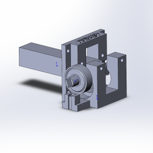
Start with press-fitting an SS495A sensor into its socket. Solder its wires and bend the legs, fix everything with drops of super glue. Then, insert the lever connector into its frame and press-fit 608zz bearings. Insert M3 screws and put nuts onto it to fix bearings in place. Put the magnet into its socket.
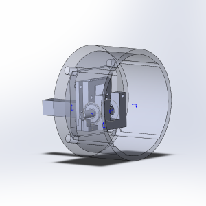
Put the frame with a connector on it into an enclosure and fix it with M3x40mm screws and nuts (we will mount tensioner halves on them later). Insert 10x10x250mm aluminum square pipe (alternatively, you can replace it with a printed part, but an aluminum pipe is stronger and will feel better).
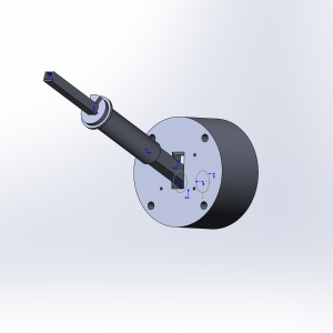
Put a decorative cover on the lever frame and the rear throttle mount part, glue the latter to the decorative cover with super glue if needed.
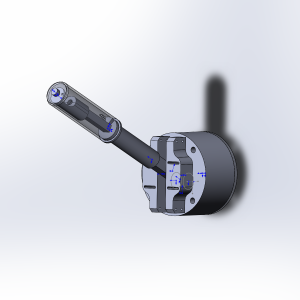
Put a potentiometer holder part onto a frame, fix the pot in it, solder and route its wires through a lever. Turn a pot to its full extent to the right, and put the throttle handle on. Press-fit a wedge into a slot of a pot handle to fix the handle. Finally, put tensioner halves on and fix them with nuts (they should be able to move but not wobble around), then screw them together with M3x50mm screws. Put the bottom cover and fix it with M8 screws after you’ll finish with soldering wires to an arduino. The mechanical part of the assembly is finished!
Videos
Electronics
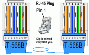
As usual, we use a half of an ordinary ethernet cable crimped as shown on the picture above to connect our collective to the controller.
Connect an Arduino Pro mini as follows:
PIN10 – SS495A/potentiometer VCC
GND – SS495A/potentiometer GND
RAW or VCC – orange-white ethernet cable wire (+5V)
GND – orange ethernet cable wire
SDA – blue ethernet cable wire
SCL – green-white ethernet cable wire
A0, A1 SS495A and potentiometer signal wires (A0 – throttle, A1 – collective, or change this in the ino file)
Flash it with the i2c_simple_collective.ino file and enjoy flying with the filtered 10-bit resolution!
Downloads
Simchair MKIII I2C latest software on GitHub
Hey,
thanks alot for your great work! Really awesome stuff you made.
I am currently starting to build my KA50 homecockpit. I printed all the parts for the single engine collective. I just ordered the parts for the collective and watched your assembly video, read the comments etc.
I saw that you connected the Collective to an I2C. There an Arduino Leonardo is used to transfer data via USB to the computer. But where does the mini board go and what does it do? Sorry for the dumb questions but I am new to electronics. Since I am a total noob I am also wondering what connectors, wires and small stuff I will need to get the collective running. Any tips on that?
Thanks in advance for your patience and help.
Grettings Felix
Hi! I am happy you like it =)
Please check out my other videos which will give you some idea of what the whole controls set looks like, and how it works in different sims.
https://youtu.be/6FUu73rrABE (hc625ma’s cozy hangar channel on YouTube)
Please check out the spring-loaded cyclic gimbal as well, as its new software pseudo force trim mode (which also supports pedals) makes flying helicopters way more realistic.
An Arduino Leonardo board is used as a master controller, that connects to peripherals through I2C bus (4 wires, 5v,GND,SDA,SCL). It is a digital protocol, so requires another board (sometimes two) in each peripheral to “talk” with the master. The cheapest and smallest one is the Arduino Pro Mini. All buttons, potentiometers, SS495A sensors are connected to these boards, so there’s only a standard ethernet cable between each peripheral and a master controller, instead of a cable maze from hell. =) There’s also a single USB cable going from the Leonardo board to a PC. Each peripheral has its own firmware.
When you plug the Leonardo board (flashed with simchair firmware) into a USB port, it auto detects and starts polling everything that is connected to it, the B8 cyclic stick also supports hot-plugging.
Now, this “simple” collective is an old one and is pretty much only good for flying RC stuff (there’s no support for that yet in the current version of hardware). The one you need is a single engine one:
http://hc625ma.org/single-engine-collective/
You need everything from the “Components” list, and I strongly advise you to look at the pneumatic mod (and its “Components” list) as well:
http://hc625ma.org/collective-pneumatic-mod/
At this point, I can’t imagine myself flying without it.
For some reason, I should say, the most underestimated thing is cyclic. That software pseudo force trim really makes a huge difference (as different travel angles do). Force trim also affects pedals like in a real helicopter, so simchair pedals worth to be made as well =)
Please feel free to ask further questions!
Cheers, Alex