Summary
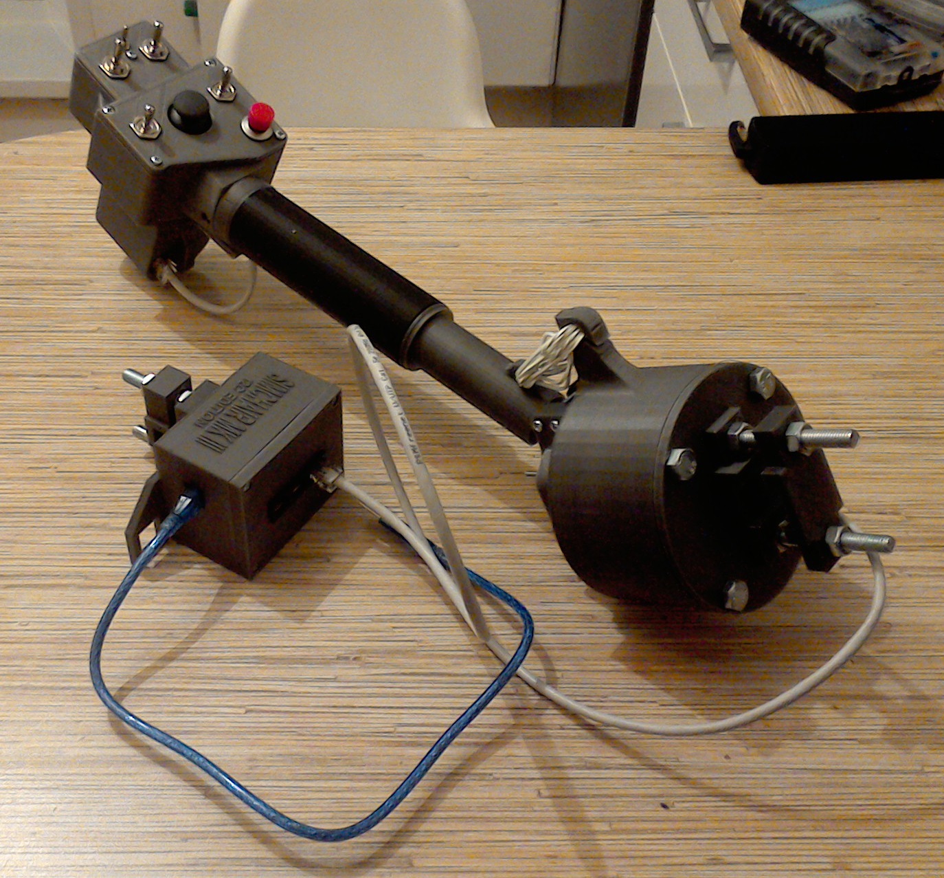

This is a UH-1-style collective head. Its dimensions are based on the measurements and photos found on the Internet, it’s almost scale. Mode switch is installed in a place of a light bulb, as it’s much more useful in this case. In its default software configuration, it’s set up in a way so you can assign switches of the DCS Huey’s head to it. It can also start a DCS Huey (it will operate its throttle below idle stop detent). Note: if you’re starting a flight cold and dark, your throttle should be closed for this feature to work properly!
Components
You will need:
1 x PLA plastic coil
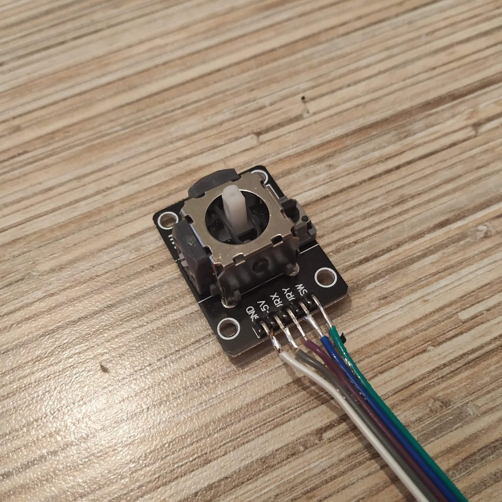
1 x KY-023 joystick module
2 x KN3(B)-223A-A3 or similar switch
1 x MTS-103 A-2
2 x KN3(B)-203A-A3 or similar switch
1 x PBS-16B
1 x PBS-10B-2
5 x M3x50mm screws
1 x M3x35mm screws
1 x M3x30MM screws
4 x M3x12mm screws
4 x M3x10mm screws
1 x TJ8-8P8 Ethernet socket
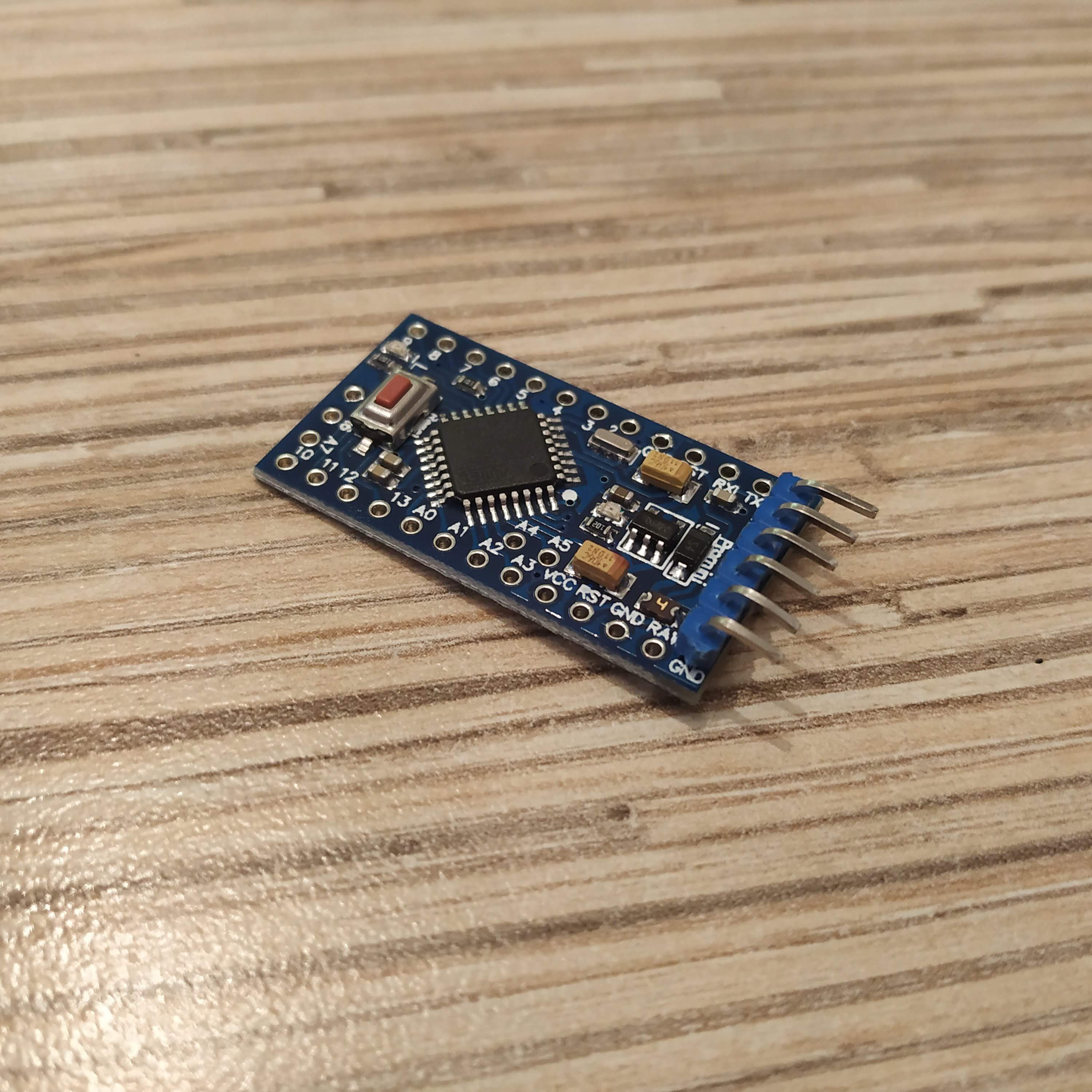
1 x Arduino Pro Mini
nuts
ribbon cable
glue gun
Available mods
none
Special features
- DCS Huey startup / shutdown support
- Collective hold (thumbstick click)
- hat switch supports 4-way or 8-way modes
- 4 switch operation modes for every possible use case scenario
- mode switch triples the number of switches / buttons configured as pushbuttons
Downloads
STLs / Sources
Controller firmware
Assembly
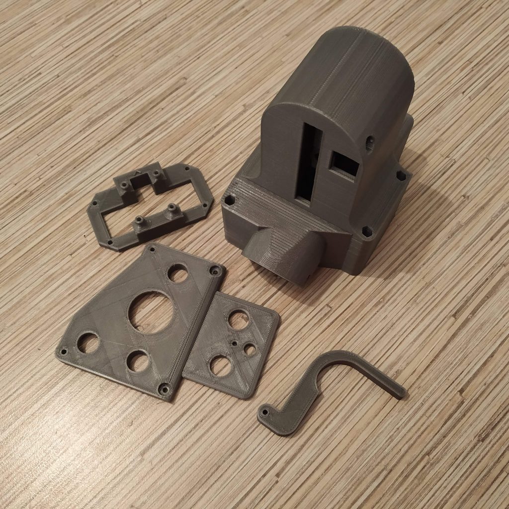
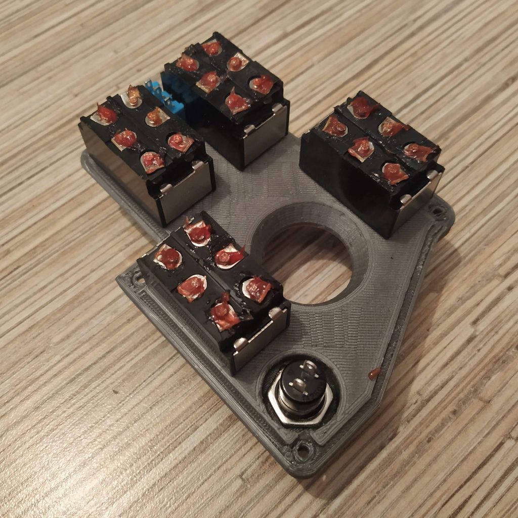
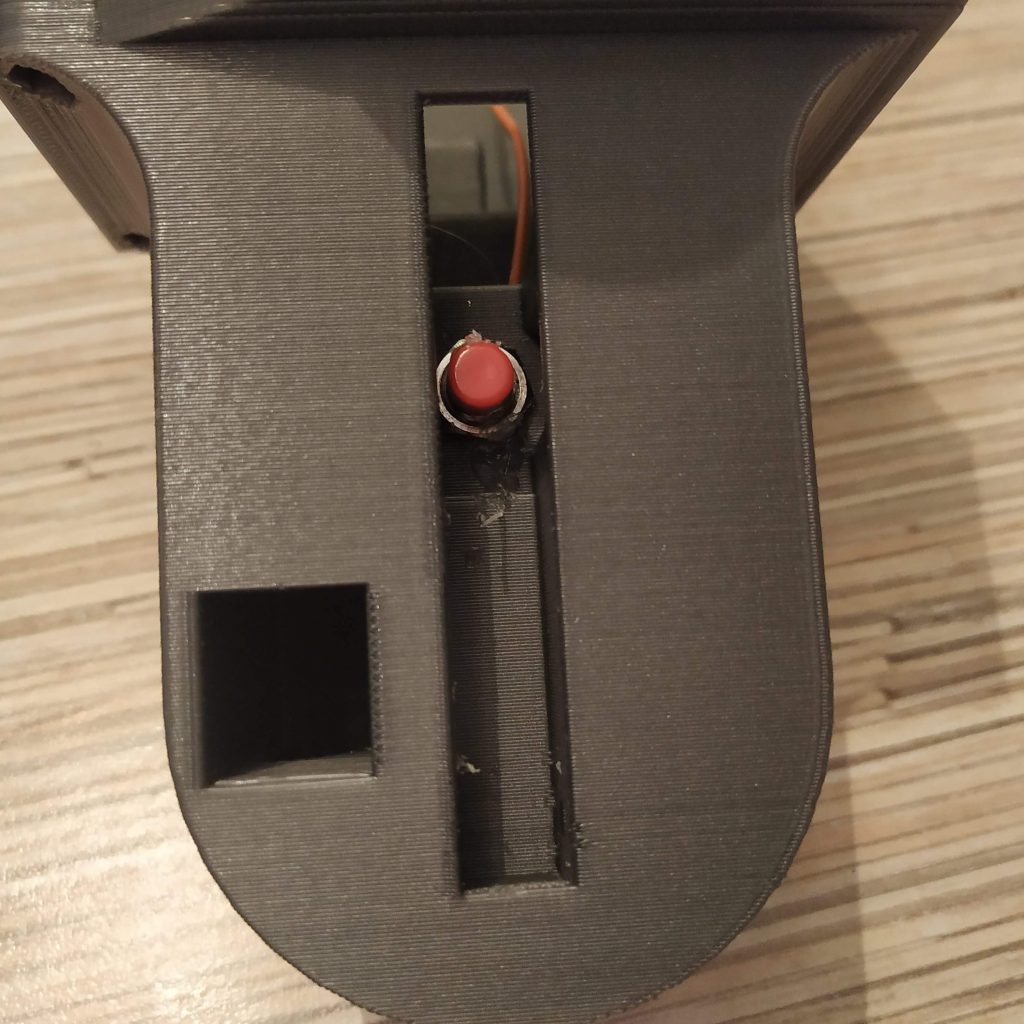
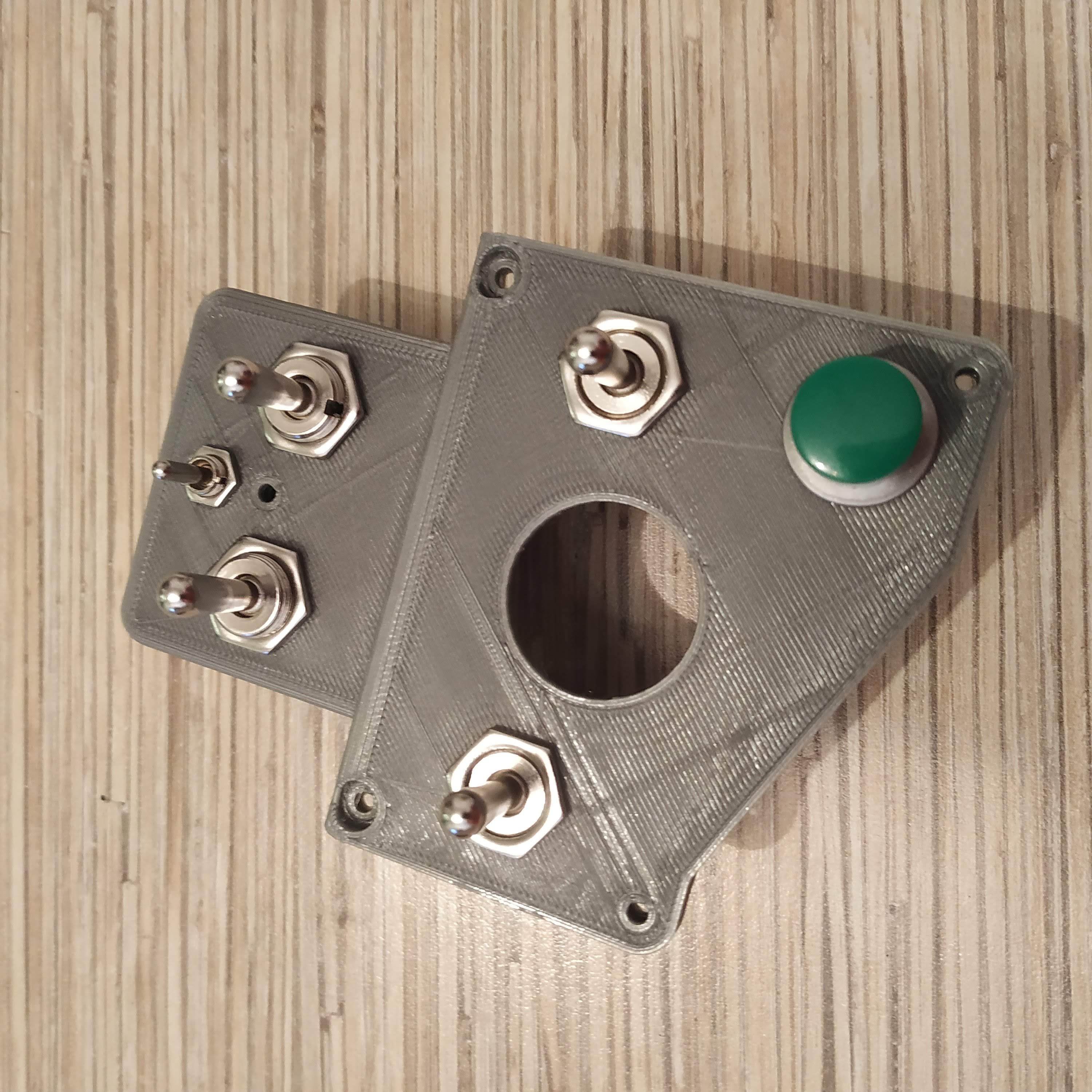
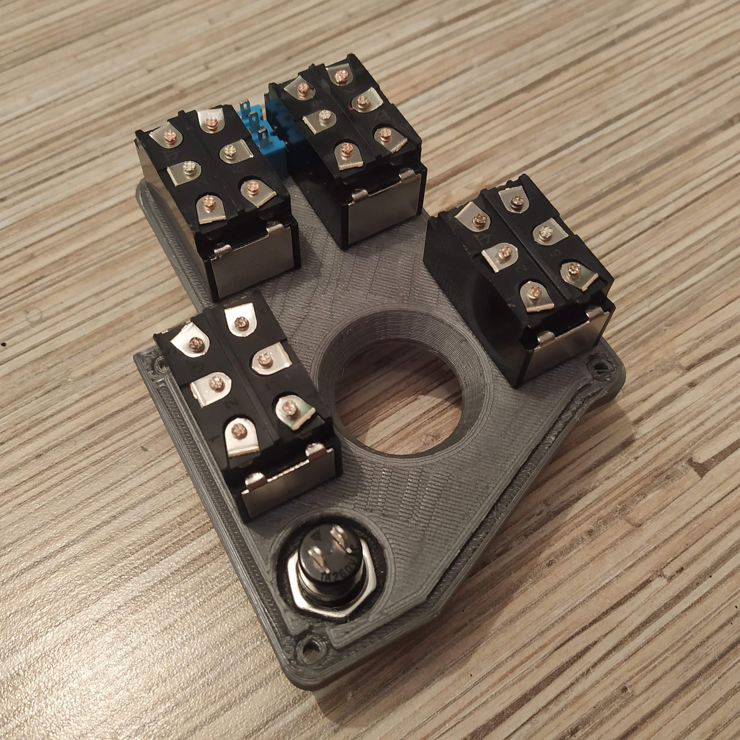
- Carefully remove supports. Note that inside of the housing there are internal structures that, in theory, can be broken accidentally (though they have been strengthened to avoid that). Press-fit nuts into their sockets on the bottom of the head.
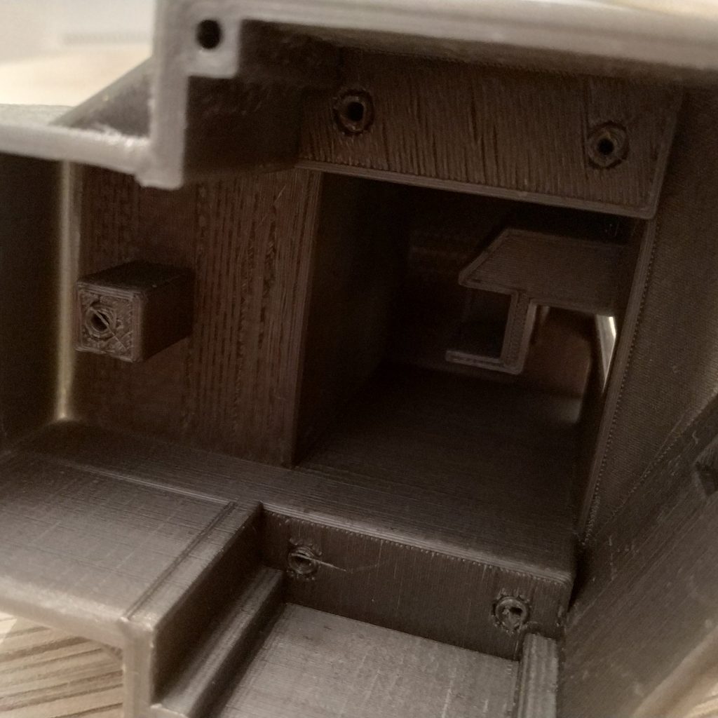
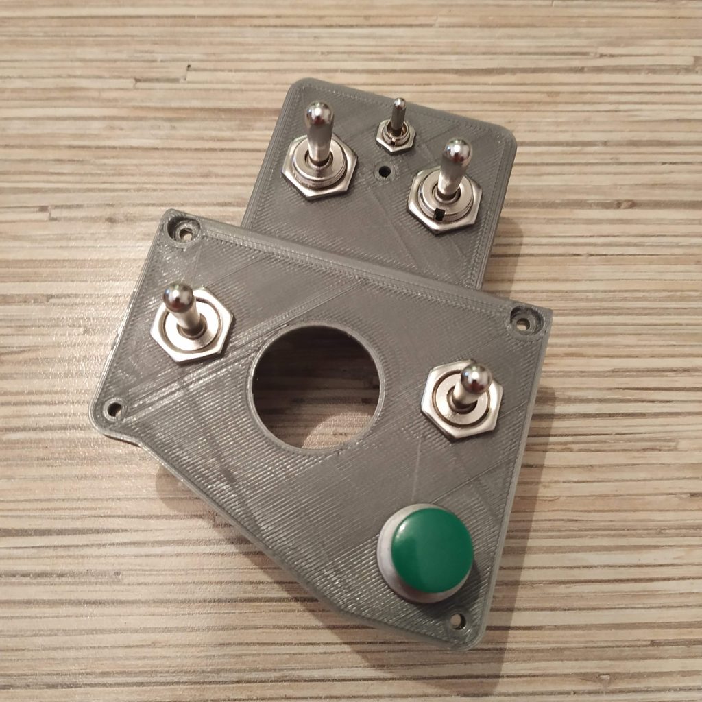
- Insert switches to the housing cover. Two switches in the bottom should be spring-loaded type ( (ON)-OFF(ON) ), two upper switches – toggle type ( ON-OFF-ON ).
- Break pin parts with screws off the switches.
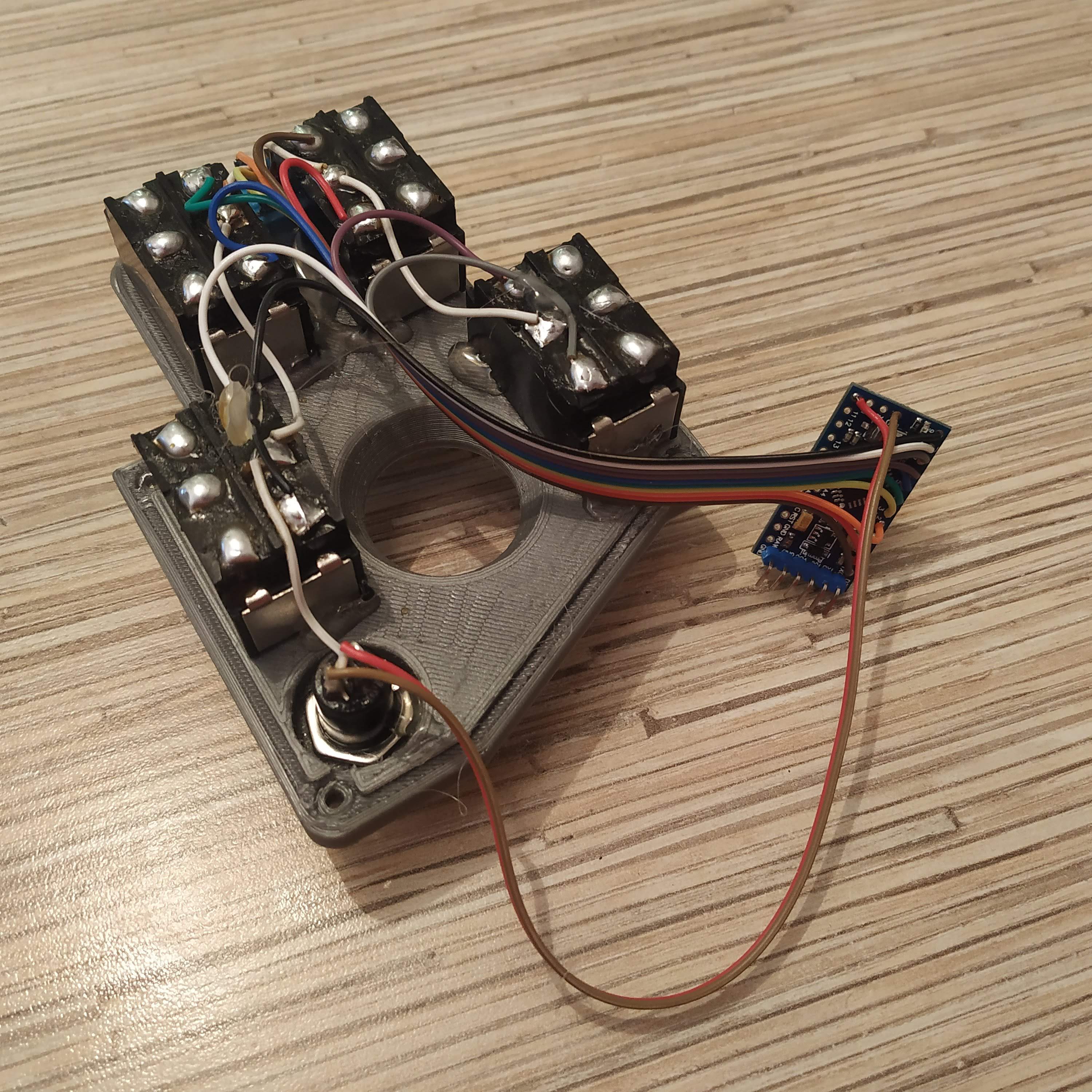
- It’s time to heat up your soldering iron and a glue gun. Put some solder onto contact pads of the switches (don’t forget to use some flux). Be careful – do not overheat switches too much.

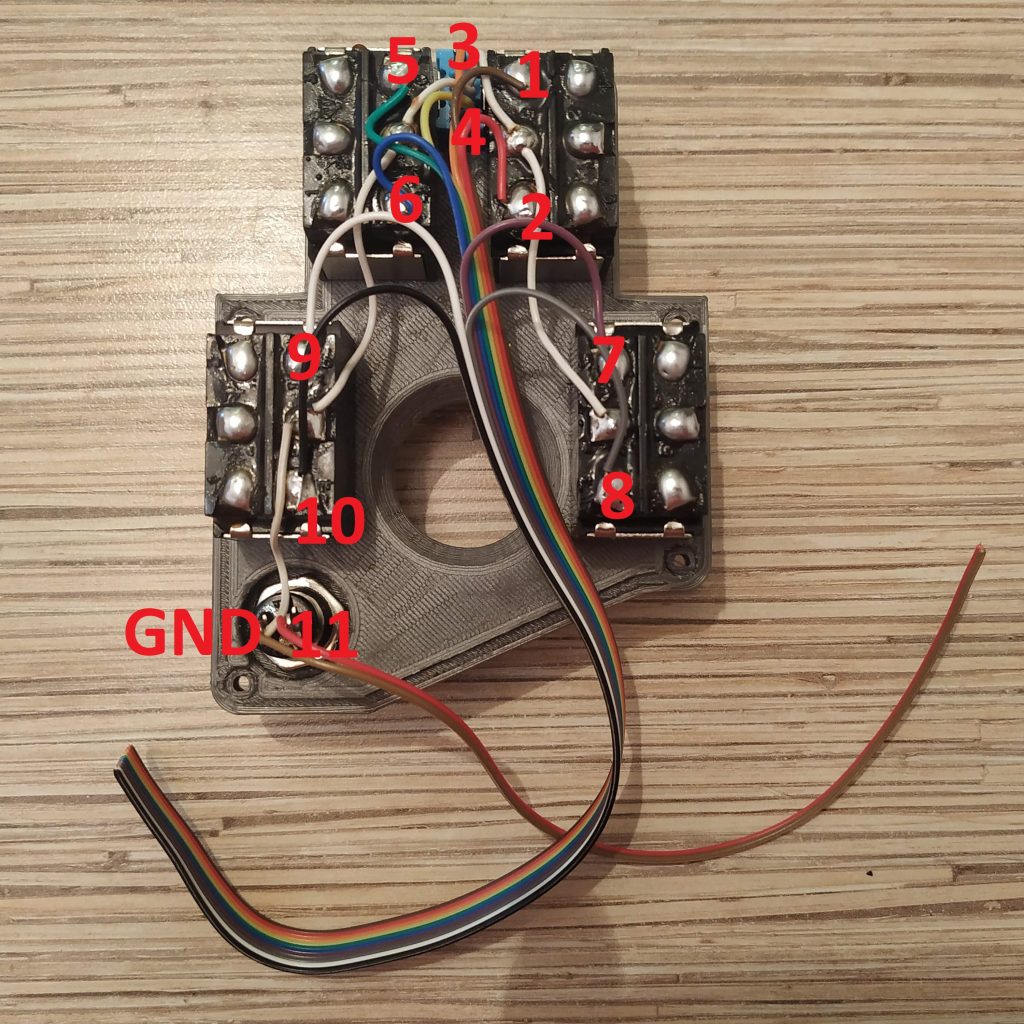
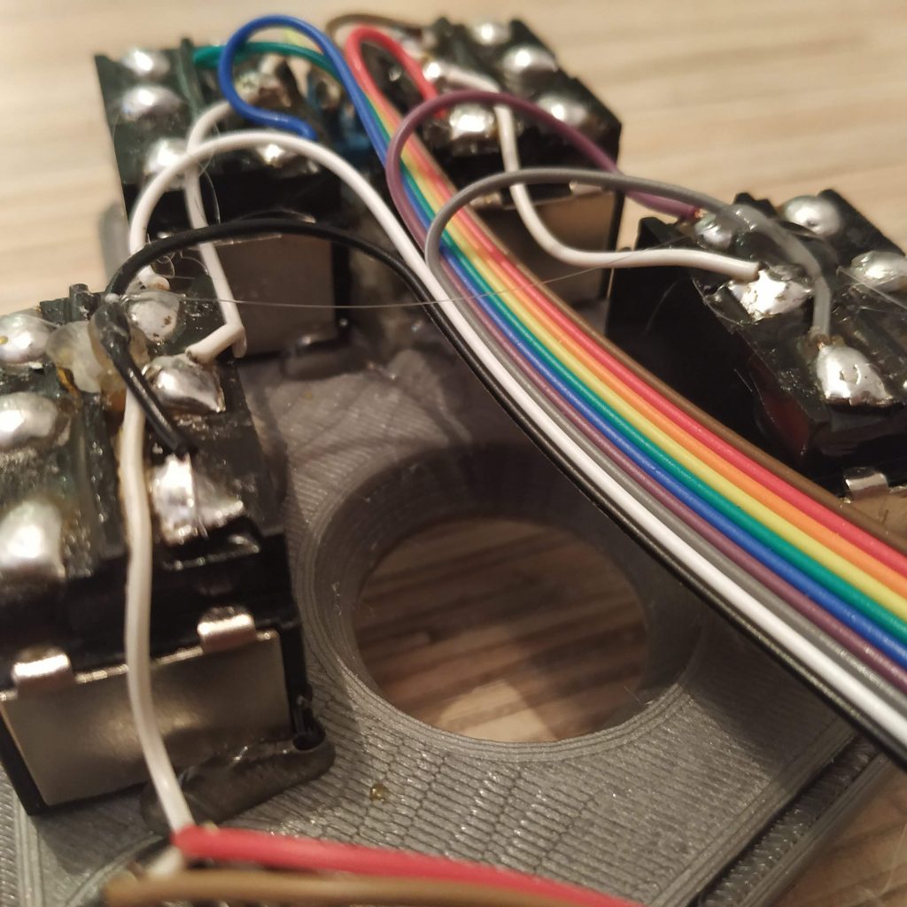
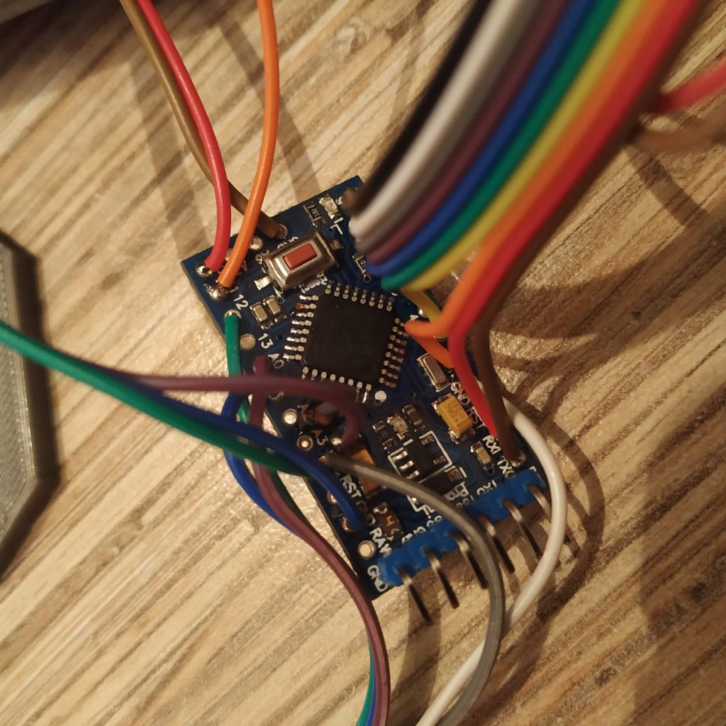
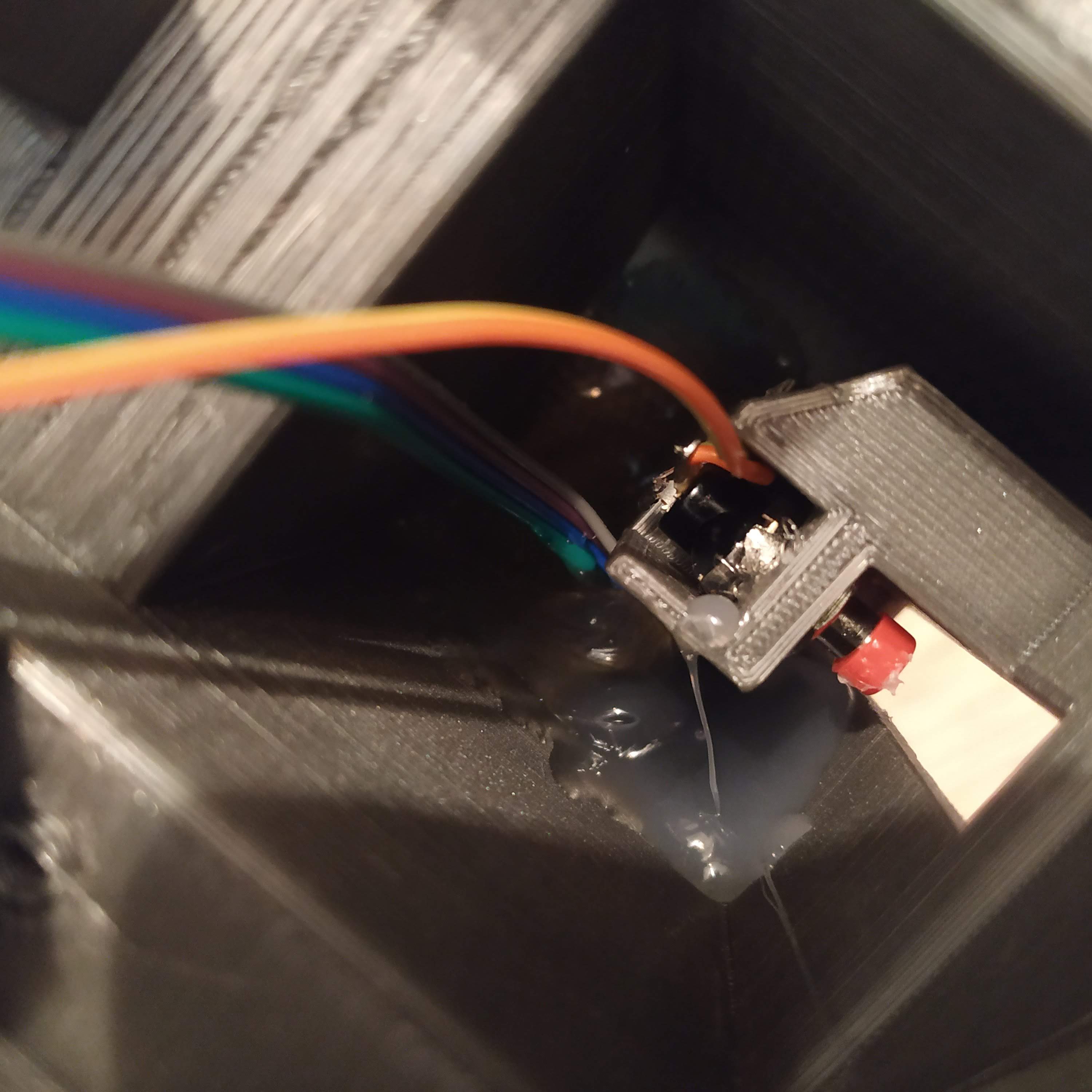
- Cut a wire off the ribbon cable, and connect ground (middle) pins of the switches and the button together, as shown on picture.
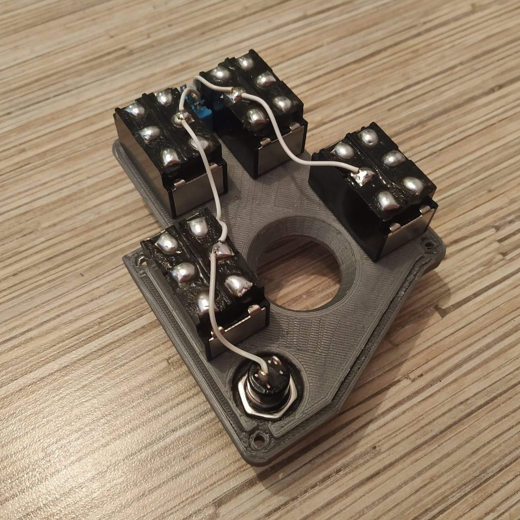
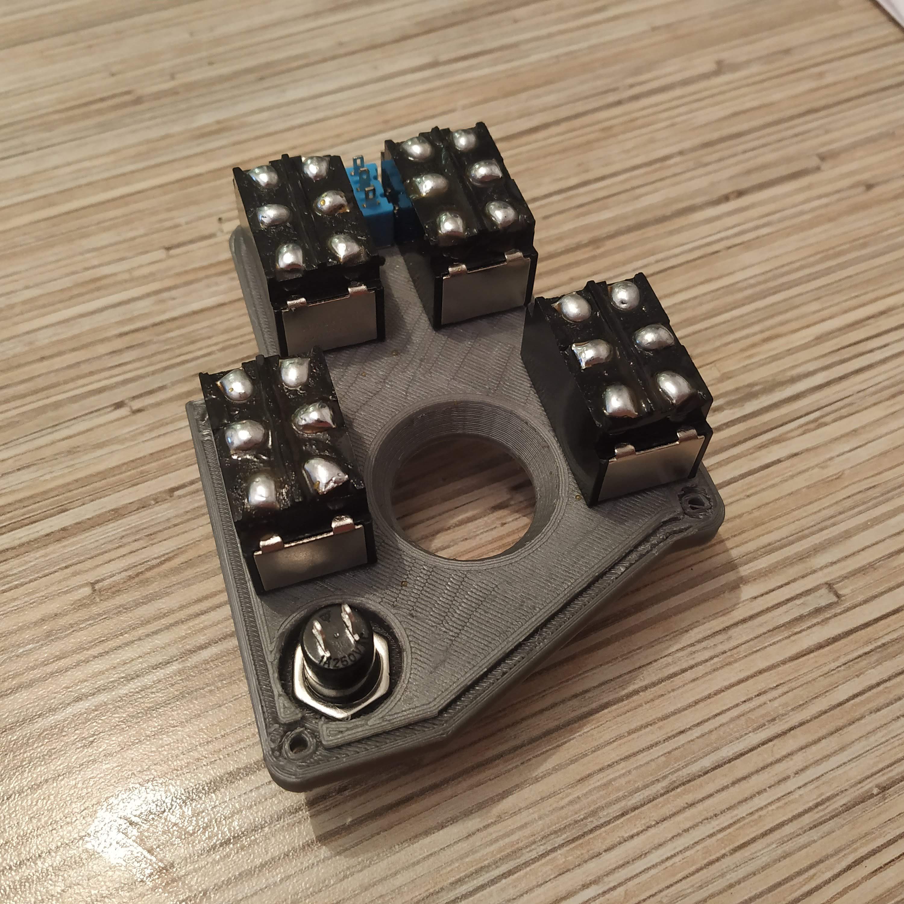
- Cut a 12-wire cable off the ribbon. Solder wires one by one, following numbers on the picture. The last wire will be the ground one. Use the same contact pads row where the ground wire is.
- Fix stuff with hot glue so it won’t move.
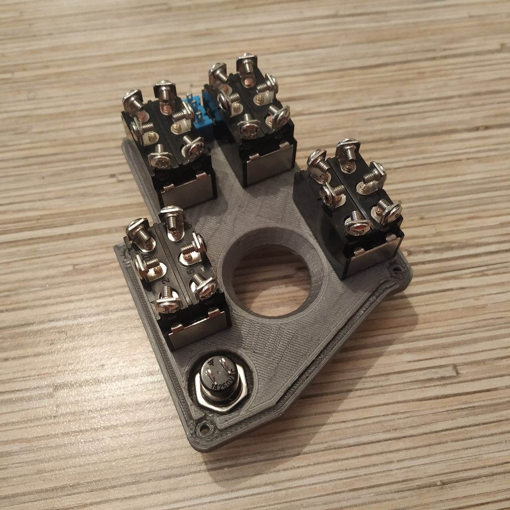
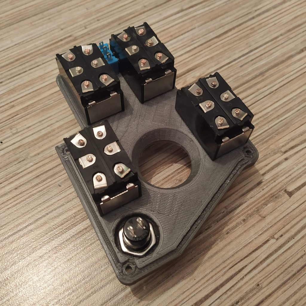
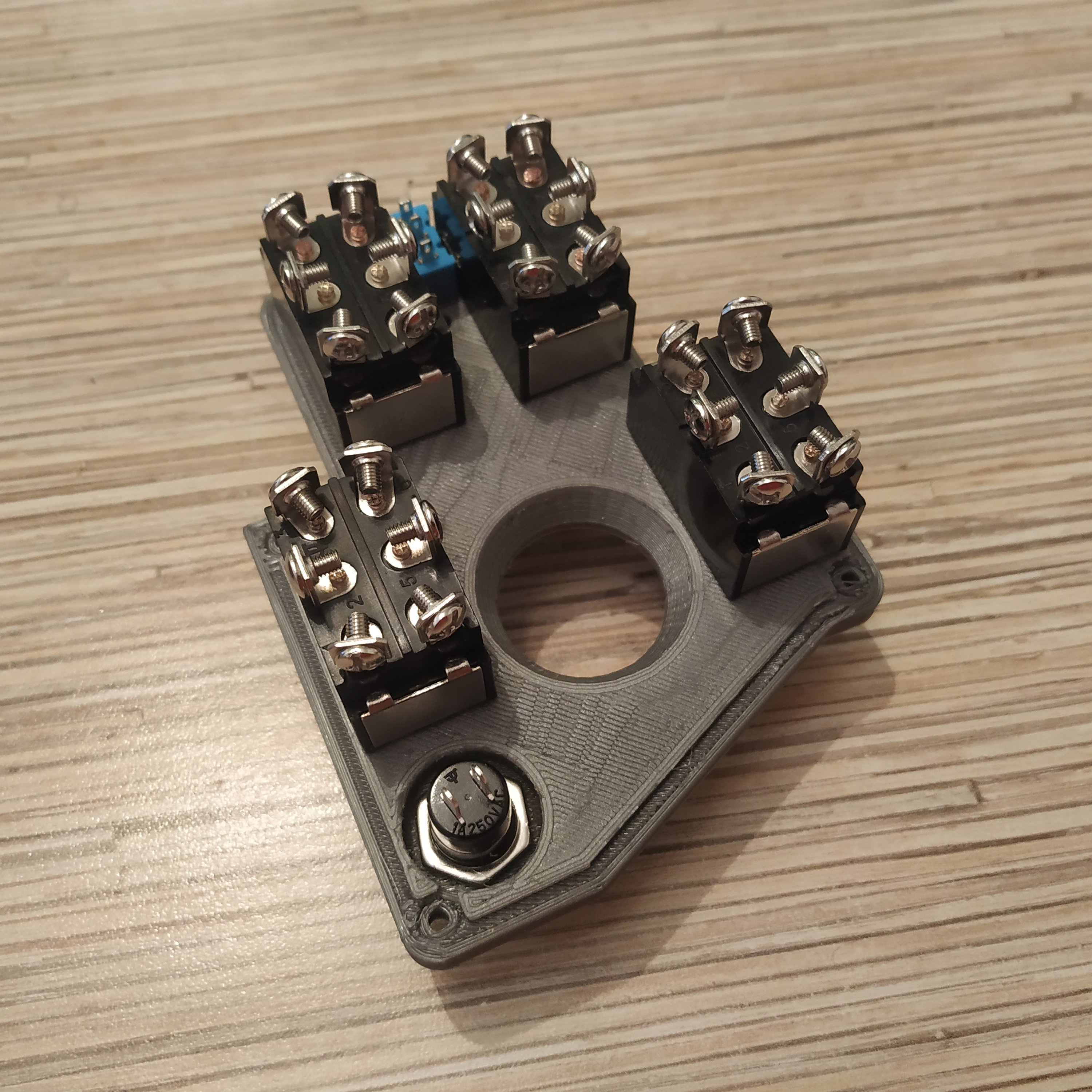
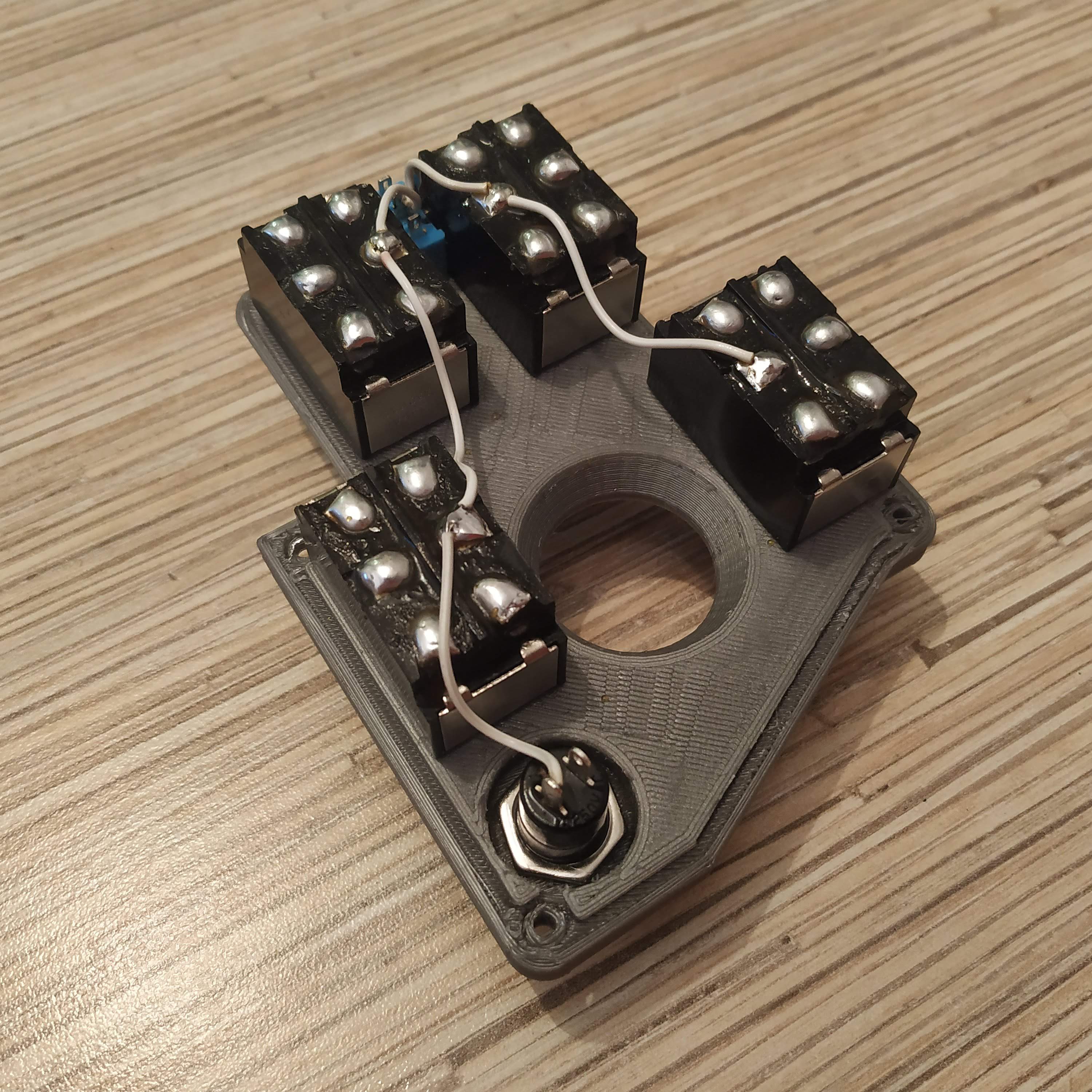
- Solder 5-wire cable, cut off the ribbon, to the pot board. Put it onto its frame, fix with 4x M3x10MM screws.
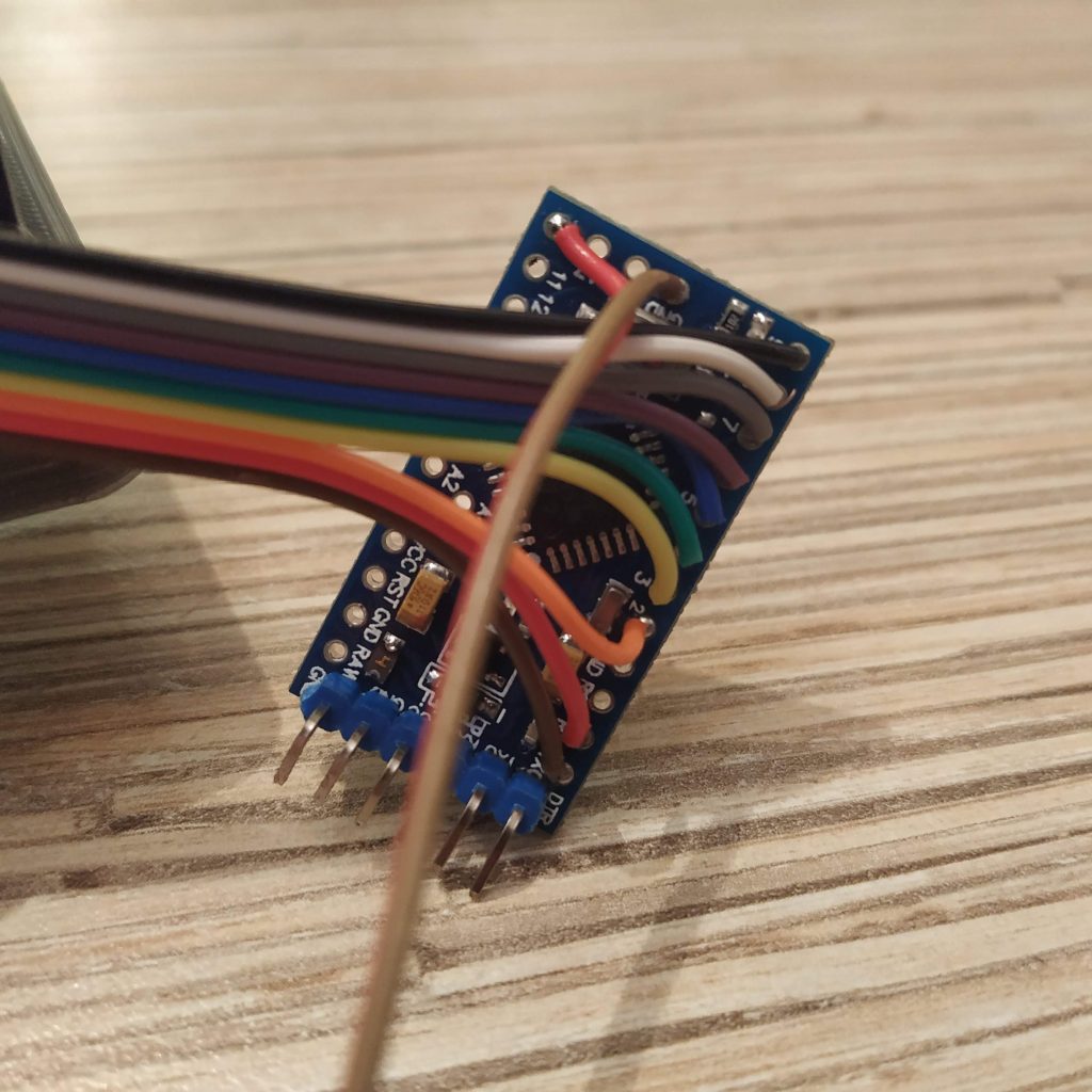
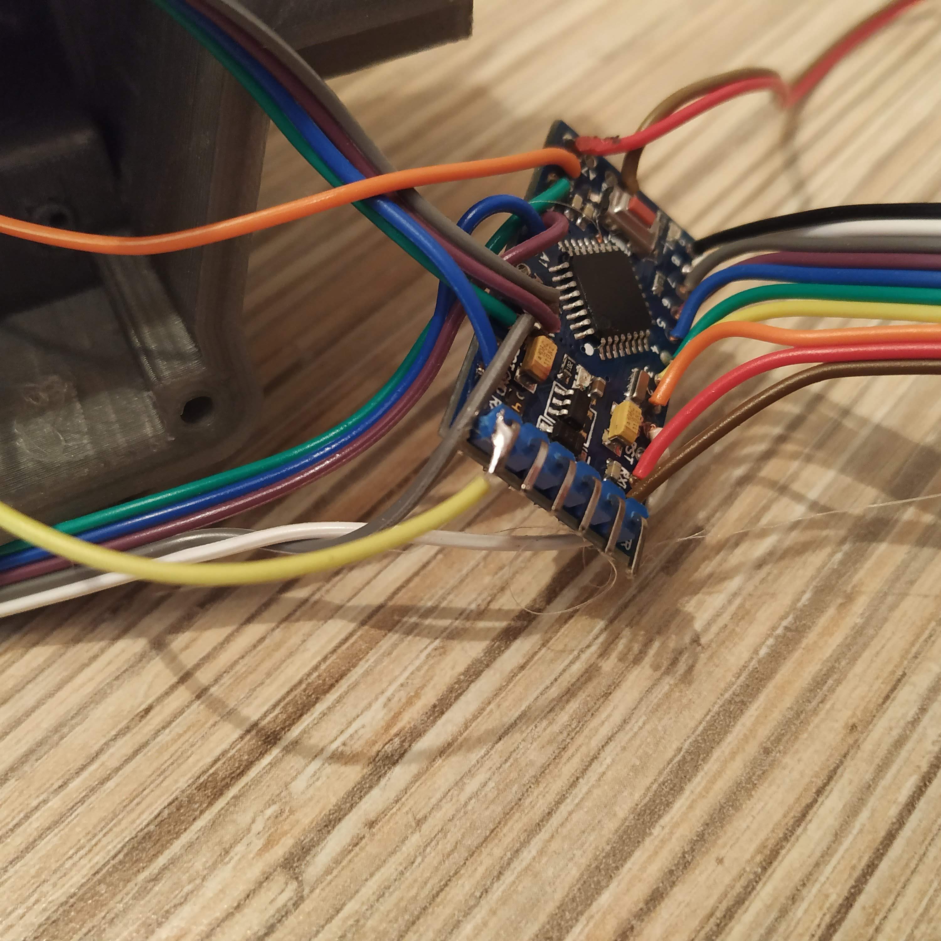
- Solder UART header to the Pro Mini.

- Starting from pin0, solder the 12-wire switches cable to Pro Mini’s digital pins. The wire of the button should go to pin10, and the last wire of the cable should go to the GND pin near it.
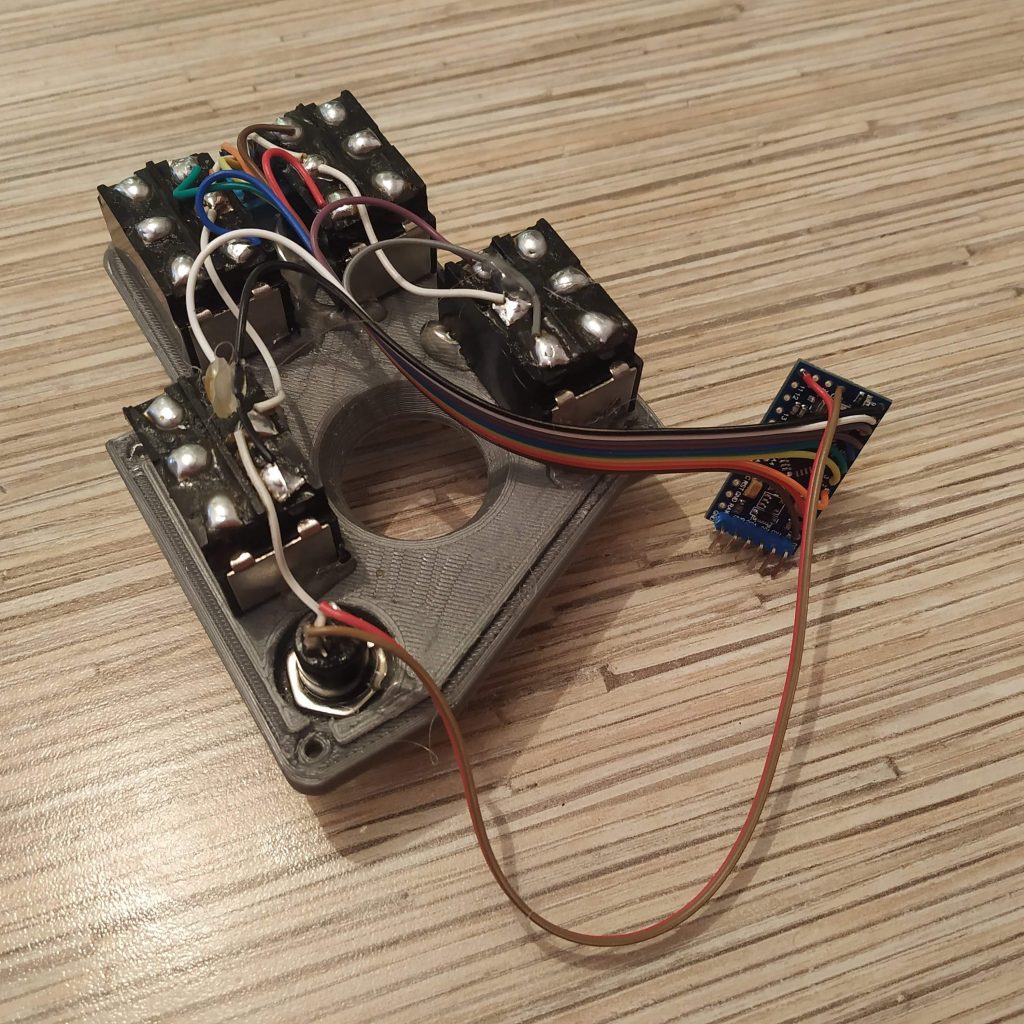
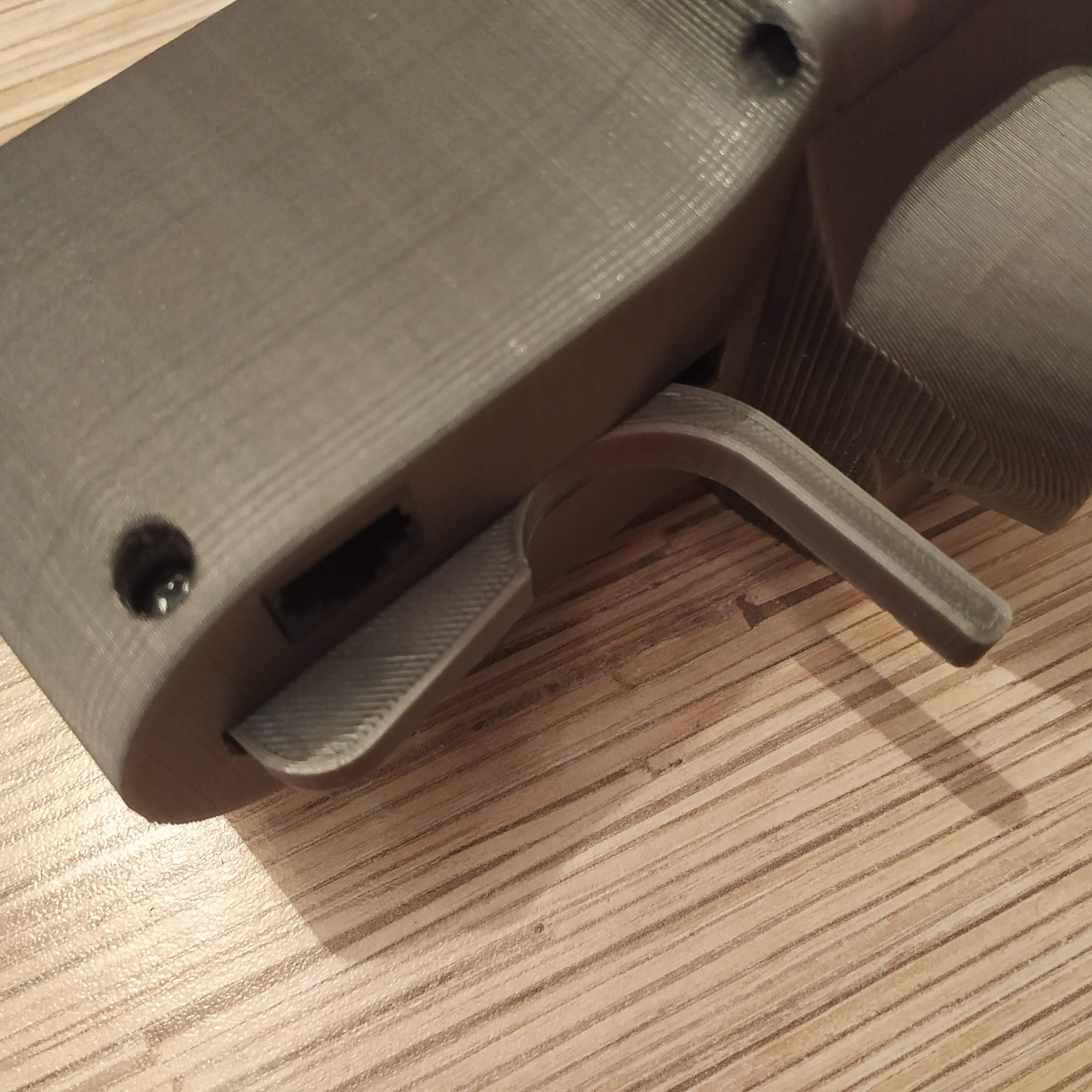
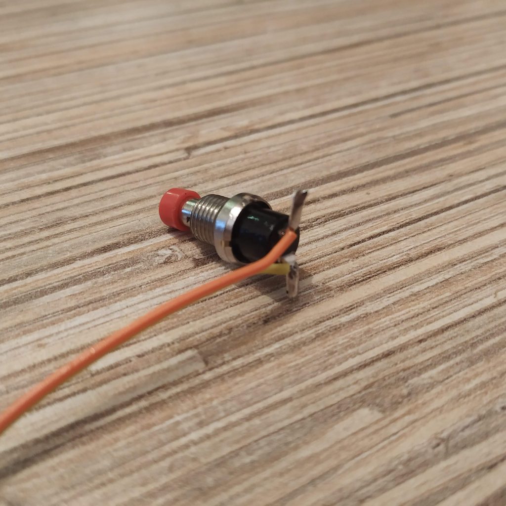
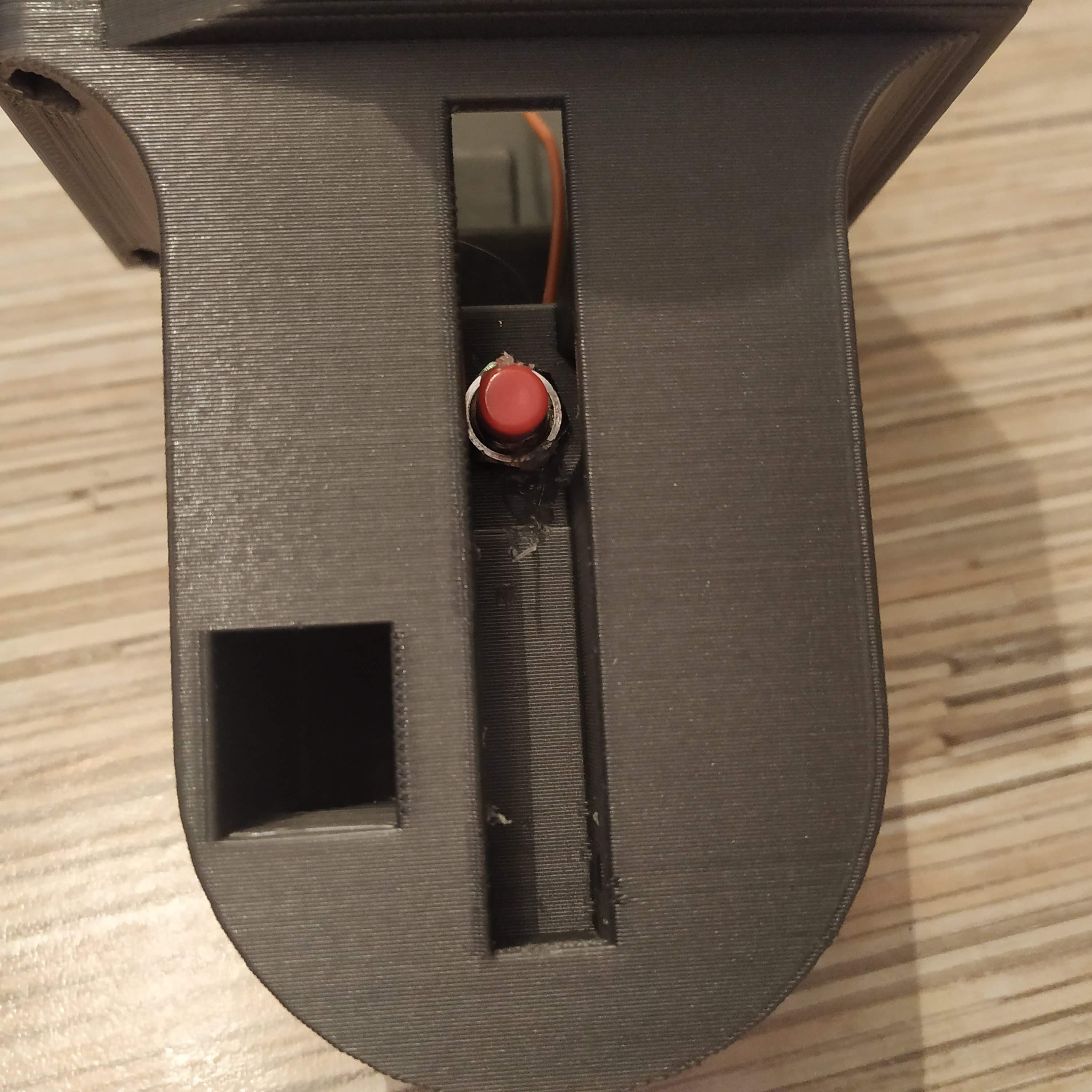
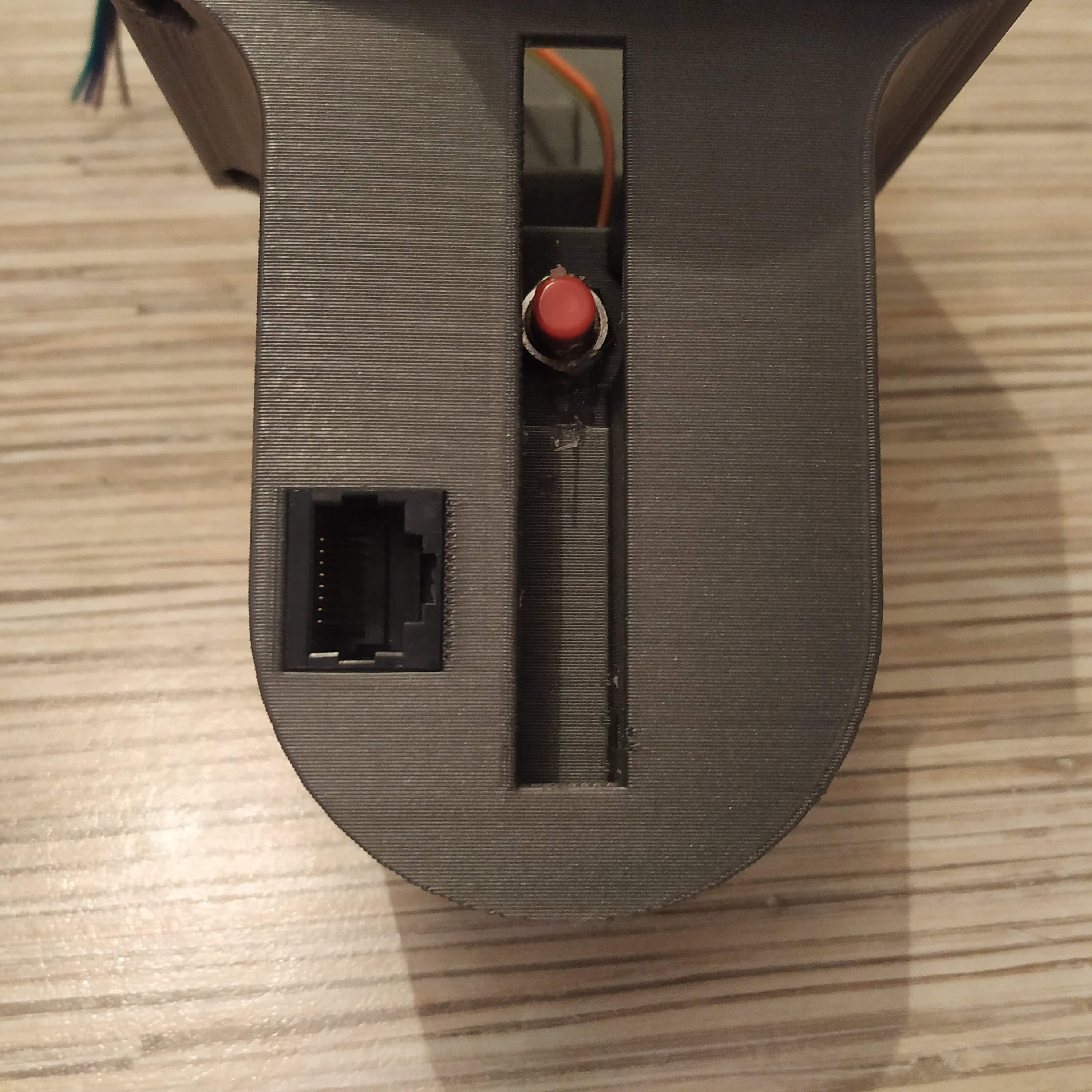
- Bend legs of PBS-10B2 button as shown on picture and solder long enough wires to it, then insert it into its socket in the lower part of the housing, fix with its nut (rotate it with pliers or a knife, tighten as possible). Use tiny drops of hot glue on both sides of the button to fix it in place.
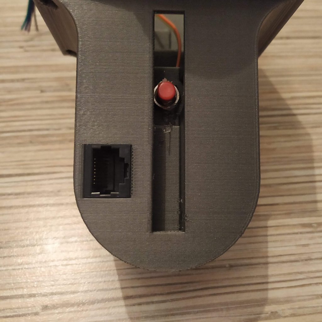
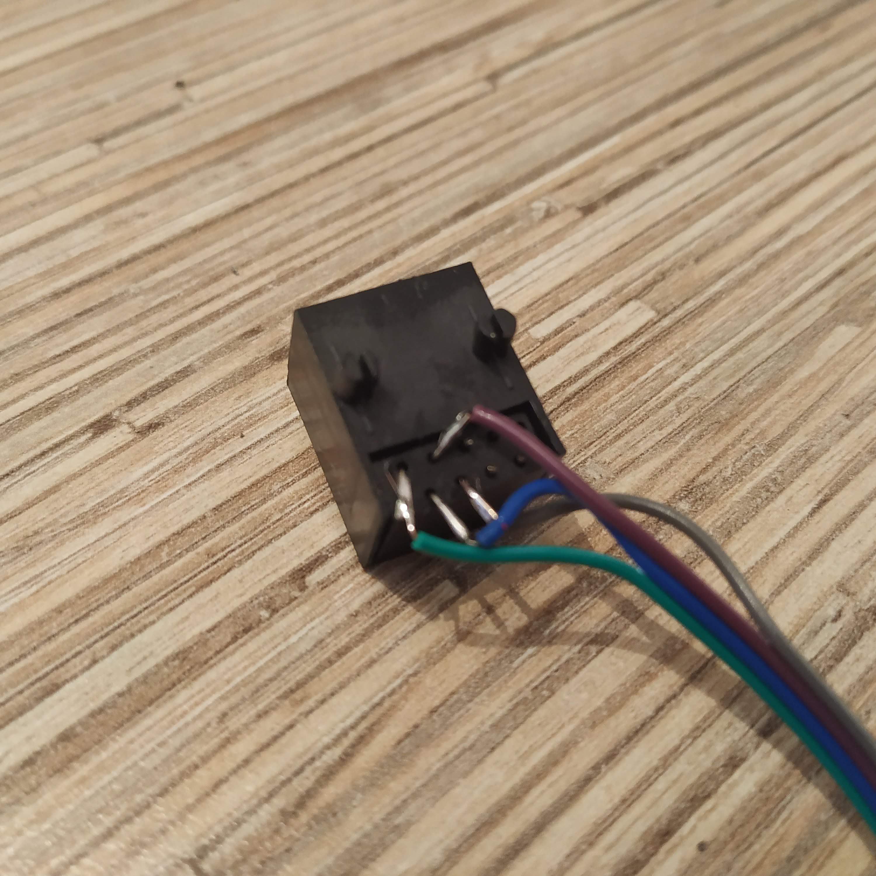
- Solder 4-wire cable to 1st 4 pins of an Ethernet socket. Cut off unneeded pins. Bend remaining pins so they won’t protrude too far.
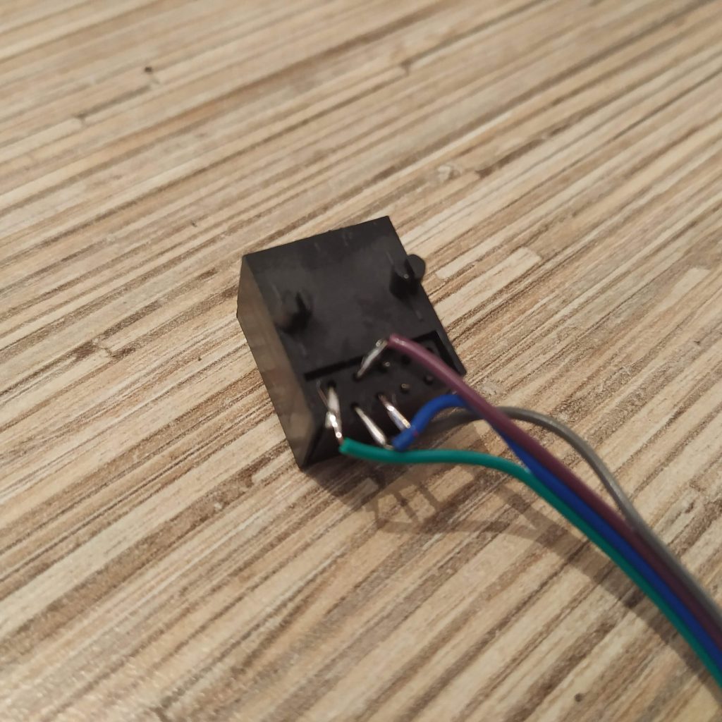
- Press-fit the socket into its slot and check that wires are still connected to the socket with a multimeter. If everything’s ok, pour a fair amount of hot glue to fix it in place.

- Solder one of starter button’s pins (PBS-10B2) to pin11, another one – to the ground. Use a spare GND pin of the UART header on the Pro Mini, or some switch’s central contact pad (the same row where wires are soldered!) at your discretion.
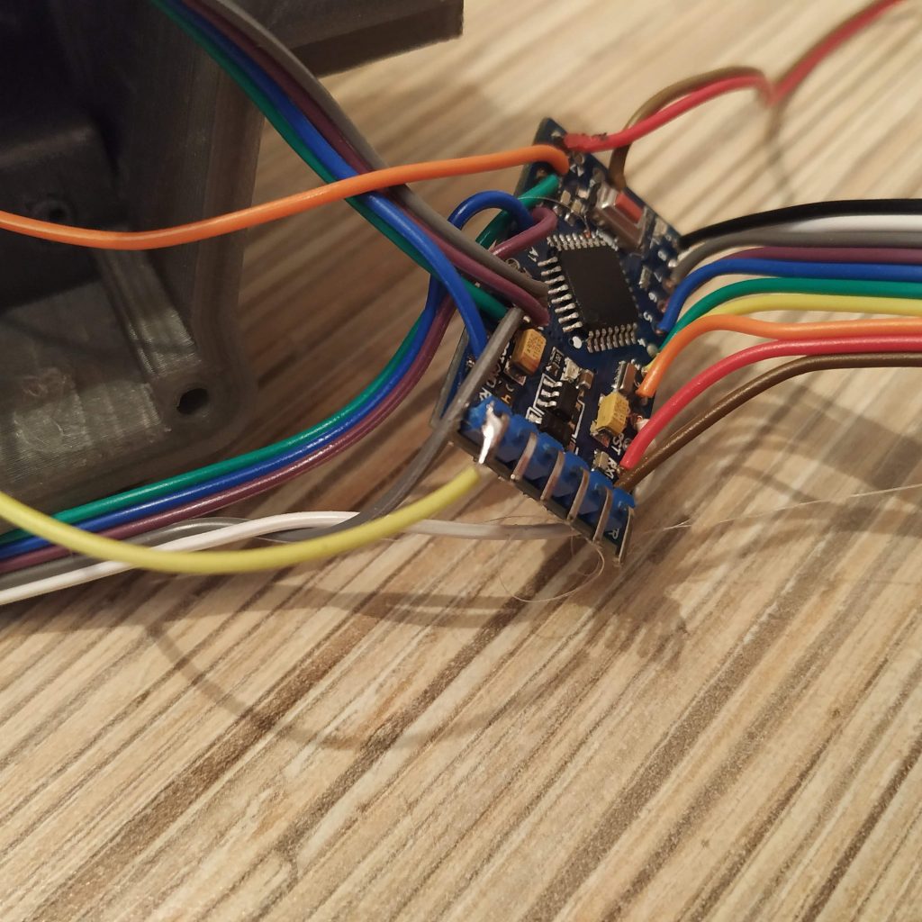
- Solder pot board wires as follows:
GND-> GND pin next to reset pin
+5V->ETHERNET SOCKET PIN 1 ->ARDUINO VCC pin
VRx->A0
VRy->A1
SW-> PIN12
- Solder ethernet soket wires as follows:
SOCKET PIN1 -> VCC (should be soldered already after the previous step)
SOCKET PIN2 -> GND
SOCKET PIN3 -> SCL (A5)
SOCKET PIN4 -> SDA (A4)
- That’s it! Time to flash Pro Mini board! Uncomment “Serial.begin” line and lines under “\\DEBUG” line. When flashing, make sure that all switches are centered.
- Open serial port monitor in Arduino IDE. You should see something like this:
00000010 00100000 124 128
Something around 128 in two last numbers means your potentiometers are connected properly (0 or 255 means there’s a problem!). Flip all switches and press all buttons (including the thumbstick button!), you should see 1s popping up in the line. Note, that the left upper switch in its lower position will temporarily cut off serial port communication, that’s fine. Just flip it back to continue.
- When you have checked all switches and buttons, comment out “Serial.begin” line and lines under “\\DEBUG” line and re-flash the firmware.
- Put everything together! Use 4x M3x50mm screws for fastening the lid and 4x12mm screws for the pot board frame.
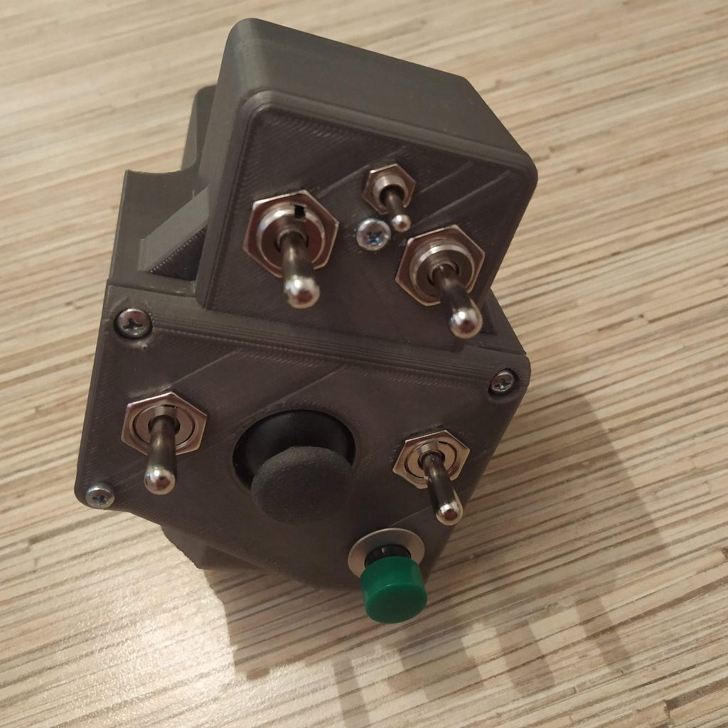
- Insert the starter trigger and fix it with an M3x30mm screw. Drill out its hole if needed to make it rotate freely. If its travel range is too short, file the lower edge of its slot just a bit.


Congratulations! Your Huey-style collective head is ready for a test flight!
Hello! Thanks for the amazing new manual!
Since I ran into a couple of unsolvable problems with my AB412 head, I decided to put that thing into the trash and start with the Huey head instead. Now I have problems sourcing the parts from Aliexpress, and I wanted to kindly ask you to help me find substitutes for the following parts
1) The PBS-16B and PBS-10B-2 buttons
2) KN3(B)-223A-A3 switch
I found the PBS-10B-2 on this website (where I already ordered parts before) but they do not have the other switches and buttons: https://www.pollin.at/p/miniatur-drucktaster-420320
Could you please help me find the parts on aliexpress or Amazon.de?
Regards
Peter
Hi! You’re welcome!
What do you mean by unsolvable problems?)
Any OFF-(ON) button for a 12mm mounting hole will do (you can always print an adapter for other sizes, or drill a larger hole!)
try something like this for a 12mm button:
https://bit.ly/2Rroy7L
for PBS-10b-B2, its better to not substitute it, as it’s inserted in a place that’s quite hard to reach (if you don’t need a scale Huey starter, you can omit it) =)
This switch has almost similar dimensions, should work (though its a bit more expensive, but may be better in quality as well):
https://bit.ly/2Vov1Qg
alternatively, you can just use the same switch you use for 2 upper switches. It’s better to have 2 different types for the sake of usability in all scenarios, but it’s perfectly ok to use what’s at hand. You can always replace switches and buttons to suit your needs.
Cheers!
Hi again!
Well, I spent hours with sanding and adjusting the parts for the head, yet there must have been some distortion problem during printing. Everything is off by a small amount (0,5-1mm). After hours of sanding and adjusting every single hole and having to recut/regrind every space for the nuts it still is not fitting properly together. The last straw was when I tried to mount the joysticks onto the little plate and the spacers just broke off because the holes and everything was off by 0,5mm. I decided that there was no space in my life for that kind of crap, so it went into the trash and I decided to make a new start.
Thanks to your help I was able to source replacement parts which should fit nicely. I will keep you informed.
Hmm, at what temperature do you print? You may need to make a chamfer for nuts etc with a knife. I usually press fit nuts with pliers (you have to press them in, they won’t just fit into sockets without slight force application), you can also use a 3mm screw to press-fit them. Just screw it from the other side (use a washer to avoid bending plastic).
One more thing to keep in mind, the 1st layer is usually wider than others, so you may need to cut stuff a bit. Increasing fan speed can be another thing to try, it will reduce shrinkage (yet can make parts brittle).
You can also try reducing layer heigth, something like 0,2 to 0,3 (depending on your nozzle size) should help. Please tell me more about your print settings =)
Also, are you using PLA to print parts? For ABS, tolerances will be too tight. Also, you have to be a jedi to print a Huey head in ABS, its a day-long print, and it usually starts to warp after an hour =)
Anyway, 1mm is a bit too much. Tolerances for everything are 0,4 – 0,5mm, that’s pretty tight fit, but not too tight to have problems with fitting stuff.
As an alternative option, you can just glue parts together =)
Hey there, nice to have the detailed manual. Thanks!
I am almost done. Just hooked up the head with the board. My problem is that as soon as I switch the SL to STOW the output of the board stops. Switching it back in the middle position turns the outut into a weird clash of signs. SOmetimes it switches back to the number output.
Measured all connections. No problems, no cross connections.
Any ideas?
Greetings
Hi! You’re welcome!
That’s perfectly normal! The reason for this is, that pins 0 and 1 are actually used for serial port communication by the board. So when you flip the switch, you ground one of these pins, that breaks the communication. It means that the switch works. Basically, you want to see that every switch flip or button press causes some changes in output, that means it’s fine electrically.
That is also described in the manual:
Note, that the left upper switch in its lower position will temporarily cut off serial port communication, that’s fine. Just flip it back to continue.
Cheers!
Thanks. SOrry for the dumb question. Just read it after checking the manual 3 times. Now I am done with the whole manual. Everything works for the slave now. I also hooked up the slave to the master and followed your manual on the software page. Is there a way to check the slave whilst being hooked to the master?
Thanks for your help! Really appreciate it!
That’s ok!
The best way to check it with the master is to open joy.cpl in windows and push some buttons =)
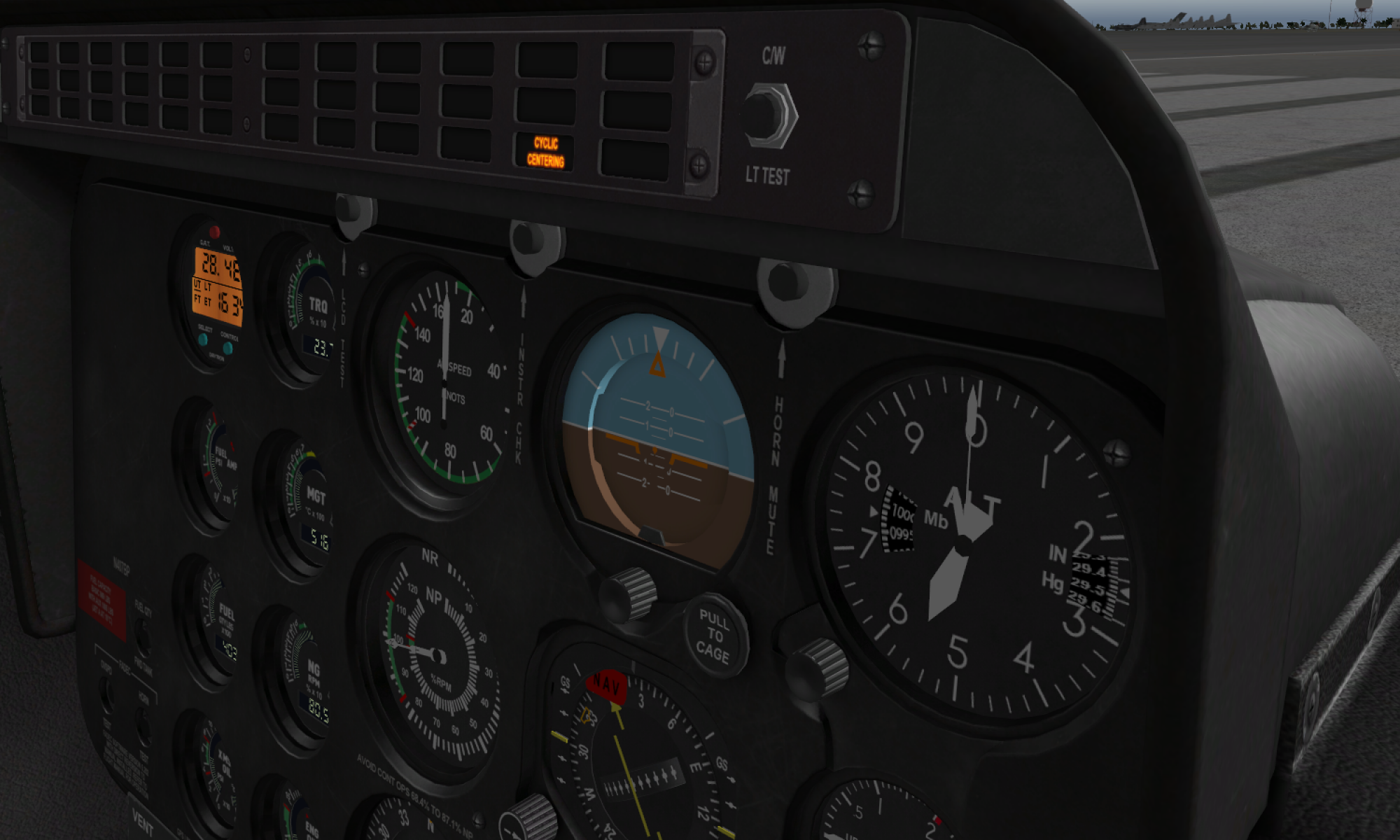
Note that mode switch (the small one in the place of a light bulb) should be centered, due to some weird joy.cpl limitations – it can display only first 32 buttons. To see all buttons in action (with mode switch in other positions) you can use Pointy’s joystick tester.
Heads pop up as a 3rd Arduino Leonardo in the list. Don’t forget to comment out Serial.begin and Serial.prints in the slave firmware and reflash it (printing to console slows things down considerably)!
Cheers!
Hello Alex! Thanks for the printing tips. Unfortunately I do not own a printer and had it printed by a friend of a friend, who is a very nice guy but not very good with 3D printing. For the Huey head I had it printed in a shop – it cost me around 150 Euros but the quality is totally different: This time it’s perfect! No warping, smooth and straight edges. Anyways, I am done with wasting time on the AB412 head. 🙂
My next problem is this -> I followed the Huey head manual until step 19. The serial output worked like expected, I reflashed as instructed. But when I try to connect the head to the IC2 bus/box through ethernet cable, it does not work. When checking in joy.cpl, the following happens:
1) Connect ONLY IC2 box -> 3x “Arduino Leonardo” appears
2) Connect collective -> The axes work in in one of the 3 Arduino Leonardos
3) Connect Huey head -> all 3 Arduinos immediately disappear from joy.cpl
The same happens if I connect only the head to the IC2 box. Also, if I connect head+IC2 box and then plug in the USB cable, the Arduinos don’t even appear in joy.cpl.
I am at a total loss… what could be wrong? Can you give me some pointers?
* I already triple-checked that it works in the serial monitor
* I checked that there is no shorting on the Pro Mini or between cables
Hi again!
From what I can think of, most likely you may have accidentally swapped I2C pins of the Pro Mini, connecting SCL wire to an SDA pin and vice versa. The white-green cable (SCL) should go to pin A5, and the blue one (SDA) should go to A4. It can be a bit confusing as in other boards, an SCL pin usually comes first. Strangely it seems I have missed it in the manual somehow.
https://cdn.sparkfun.com/r/600-600/assets/learn_tutorials/1/0/4/graphicalDatasheet.png
The problem may also be on the lever side! Try checking the head separately by connecting it to the controller directly.
Anyway, don’t worry, you’re almost there.
Heads are recognized as a 3rd Arduino in the list. The reason for 3 Arduinos thing is weird joystick related limitations of Windows – 7 axes, 32 buttons, and 2 hat switches. Some games support a larger number of buttons, some don’t, so that’s a workaround.
Btw, I am glad to hear that tolerances worked well when you have printed stuff in the shop! =)
Cheers!
Looking at the “uh1_head.ino” file that is uploaded it contains the comment “//WARNING! REMOVE LED ON PIN 13!” . Do you need to really remove the LED? Its removal is not referenced in the Manual on this page and I am not sure what impact it would have if it not removed… I did not even notice that warning, my mistake. So in my case the LED was left in place when I flashed the Pro Mini after enabling the serial port for testing with the Serial Monitor. When I tried to test the Head was connected to the Collective, which was connected to the Master and no other devices I was not seeing any Serial communications. I tried disabling the Serial, reflashing it and testing using the Windows Joystick Setup and the head did not work in that case either. But is did see that the Collective was working with it connected to it.
I then noticed the warning and remove the LED and tried tested again in Windows and saw no difference. Enabled Serial, Reflashed and still saw no serial communications. I looked at all my wiring in the head did not see any mistakes or shorts so I am at a loss and would like to know what the reason for removing the LED from PIN13 was.
In the meantime, I plan to test again this evening with just the Head and Master to eliminate the potential issue of a short in the wiring that is inside the collective handle.
While working on the head and its failed testing issues, I have been messing with everything else I have made and having a lot of fun with it. Thus far I have made the Reinforced Gimble that has a slightly different spring setup, the Stick, and Single Eng. Collective without a head… The rudder setup I am using is based off of an old Thurstmaster Setup where I just glued on the magnet and SS495A sensor in place of it’s original POT and used the source as is. I have been using it a bit and still have to address update the stick to address the twist when using single long bolts. All in all I am very pleased with how the project has come together. Thanks for all your efforts.
Hi Roger!
The reason for removing led on pin 13 is simple – if you don’t remove it, the button you connect to it will be always pressed. However, the Huey head doesn’t use pin13, so it must have been copied from the 412 head =) Will fix that.
Make sure that the switch, connected to pins 0 and 1, is centered when trying to connect to the board through serial! Otherwise, it will simply block communication by grounding on of pins needed for it =)
Are you sure you have not mistaken the order of SCL and SDA pins on the Pro Mini? A4 is SDA, A5 is SCL.
As you have noticed, you could have accidentally damaged the cable that goes through the lever. If the board flashed successfully, and you have uncommented Serial.begin and Serial.prints, the switch on pins 0 and 1 is centered, at least serial should work!
Please let me know how it goes. I am happy that you liked the project =)
Cheers!
Hi again, thanks for your help!
I was very busy until today but now I had some time to try your suggestions: switching the SCL/SDA cables. The result was the same, however: After 1 second the 3 Ardinos disappear from joy.cpl. This is immensely frustrating, I am really unhappy. My time is EXTREMELY limited and wasting precious minutes of free time on debugging this thing is not good. Sorry for venting! It’s not your fault, of course! I am just very desperate…
This is, what I did:
1) Check if there are any short circuits between any wires – there are none! I checked ALL wires at all possible spots.
2) Check if there are any short circuits between any of the IC2 wires. Checked at all possible locations. There IS current flowing when testing, but no short circuits.
3) Triple-checked that SCL (Green/white wire, pin 3) -> A5
4) Triple-checked that SDA (Blue wire, pin 4) -> A4
5) Connected the head directly to the IC2 controller -> the Arduinos disappear from joy.cpl immediately. Remove the head, the Arduinos reappear after a while.
6) Switched the Green/white and blue wires. So that SCL -> A4, SDA -> A5
7) Connected head directly to the IC2 controller -> the Arduinos disappear from joy.cpl immediately. Remove the head, the Arduinos reappear after a while.
So the result is the SAME! It does not matter if SCL/SDA Is correct or flipped!
8) Resoldered SCL/SDA to the correct points on the pro mini.
9) Redownloaded firmware for Huey head, reflashed, checked degubbing output in serial monitor (all switches and buttons work as expected), reflashed with Debug sections commented out.
10) Connected the head dirctely to the IC2 controller -> the Arduinos disappear from joy.cpl immediately. Remove the head, the Arduinos reappear after a while.
11) Redownloaded firmware for the IC master controller, reflashed, rebooted it.
12 ) Connected the head directly to the IC2 controller -> the Arduinos disappear from joy.cpl immediately. Remove the head, the Arduinos reappear after a while.
13) Connected the head to the collective and the collective to the IC2 controller -> the Arduinos disappear from joy.cpl immediately. Remove the head, the Arduinos reappear after a while.
So whatever I do, the result is the same. I am pretty desperate at this point. The collective itself works fine. The head works in debugging mode but not when connected. What to do???
Are you sure you haven’t mistaken with the order of pins in the socket? When you plug the head in and joysticks disappear – it most likely may mean that Leonardo reboots due to reversed polarity of a connected device or a short circuit. The problem looks like a problem with socket – as the board itself works when connected to serial. Try taking a similar socket and checking which pin corresponds to which pin of the plug!
Or simply power the head through serial, and check that 1st pin of the socket where the orange-white wire of the plug goes has 5v on it, the second (orange) is GND. Third should be SCL (green-white), 4th(blue) – SDA.
There’s also a possibility of a glitchy Pro Mini board, but it’s kinda unlikely.
It’s really strange that you have run into these issues – I have built 5 or 6 of these heads, the last one following this manual, all worked right away…
Don’t worry, everything will work, just need to pinpoint the problem.
Thanks for your suggestions! It got me thinking. OK, after spending a lot of time thinking and staring at the ceiling while lying in bed, it occured to me that I check in great detail if there is current flowing, but not how MUCH.
So I rechecked everything, starting from the post on the IC2 box and guess what I found out: At the IC2 box, there are 4,82V but in the Huey head there only arrive 0,8V! I pinpointed the problem to the network connector in the Huey head. Somethign in ther was broken. I exchanged it for another socket and now 4,82V arrive in the head. I checked with joy.cpl and every switch and except for the little one (upper middle one) works! This is what I see in joy.cpl: https://imgur.com/QtC8czF
Is that correct?
Congratulations! Everything looks good now. The little switch in place of a light bulb is a mode switch! To see it in action, download Pointy’s joystick tester from here:
http://www.planetpointy.co.uk/joystick-test-application/
This is needed because of weird Windows limitations: joy.cpl only shows 1st 32 buttons of the joystick. The head uses 96 buttons!
Two buttons that are pressed are configured as buttons with “middle button” support. They are configured in master controller sketch, look here:
http://hc625ma.org/ab412-collective-head/#comment-167
there are similar arrays for the Huey head in a_configuration.ino.
Cheers!
Hello again! Thanks again for your help! But I finally managed to get nearly everything to work.
Had to take apart the collective again (set up the pot deadzone wrong) and resolder everything in the collective base (some solder joints were wonky and I had some shorting issues).
Did set up and calibrate the idle stop position in the config files.
But I am still a bit puzzled on how it should work in DCS. The idle stop button works! But when I lower the throttle (on the collective) below “zero”, nothing happens. I still have to press “Page down” on my keyboard. It’S not a major issue, but I am scratching my head because of this. It all seems to be set up properly in the .ino files.
How could I troubleshoot this?
Hi Peter! Thank you for a donation, really appreciate it!
Looks like I have accidentally broken it in one of latest updates! Looking into it now.
Normally, it works like this:
Due to how it is done in DCS, when the head is set to mode 0 (mode switch centered) when you turn throttle grip counterclockwise, it should send PgUp keypresses to the sim. Then, when you turn it below idle stop while holding the idle cutoff button, it sends PgDown presses.
Make sure the throttle is closed when starting cold and dark for it to work properly =)
Will hopefully fix it today.—-UPD—
Here’s the fix:
in z_shared_options.ino, find the following function:
uint16_t coll_head_idle_stop_compat_dcs (uint16_t throttle0, uint16_t throttle1, uint16_t idle_val0, uint16_t idle_val1)
In it, change the line:
for (byte i = 0; i < sizeof(ab412_coll_head_idle_stop_buttons);i++)
to
for (byte i = 0; i < 2;i++)
Alternatively, just update and reflash the firmware – I have just pushed this fix to the repo.
Ty for noticing this =)
Btw, have you tried the pneumatic mod already?
Cheers!
Wow, that was fast! I will make sure to try it this weekend!
No, I do not plan on doing the pneumatic mod. Instead I need to figure out a little connector piece to make the collective sit “higher”, because with my chair it is about 10-15cm too low, causing me back pain because when flying, I constantly have to lean left and down to reach it.
The donation is just a little tip, considering the amount of time and work you put into this! Thanks again!
p.s.: My next project will probably be this one: https://forums.eagle.ru/showthread.php?t=218874
I saw it, I got starry eyes, I felt a deep longing and love in my heart…. Haha…. We will see what will happen when I finally fix the collective height.
It looks great, but may not be so practical in VR… And once you try flying in VR, its hard to impossible to return to flying with a monitor. And as with iVRy software, you can try it even with a mid-range Android phone if you don’t have a dedicated HMD yet… =)
Btw if you haven’t yet tried it, I strongly advise you to do it, it really is a game changer! It looks quite good on my MI A2 with BoboVR Z4.
Hello again! Sorry for the long delay, I was very busy…
You are absolutely right about VR!! I am in the very lucky position of owning an Odyssey+ and loving it dearly. That thing is amazing! Before that I was lucky to own a Vive, which also was great for its time.
The only time I am flying in 2D, is when learning a new plane/helo or assigning buttons or doing other testing stuff. 🙂
But now I am having the first world problem of haptic feedback…. I tried many solutions:
* classic mouse (annoying because I have to fumble and search for it)
* Joystick button assigned to mouse click (gives me a stiff neck because of the unnatural aiming with my head)
* Logitech MX Ergo trackball (works best of all the things I tried, but it still sucks)
* the VR controllers (not really supported, clumsy, again lots of fumbling)
My idea was to have an input solution that feels “natural”. Looking forward to this device: https://forums.eagle.ru/showthread.php?t=218861
In the meanwhile I am searching for alternatives like the one linked above. Or this one: https://forums.eagle.ru/showthread.php?t=231992
Hmm this device is really interesting! I am a big fan of not using hardware switches at all (lol), because assigning them for every helicopter is a pain, they are placed differently in every heli, and having overhead panel switches on your collective or smth kinda ruins immersion a bit =)
Also, one has to remember, which of these 50 switches he’ve assigned for some function 5 days ago when he had a chance to fly for an hour. This is all a pain, so clickable cockpit is a big deal (also no one has enough switches to implement all of the circuit breakers, etc).
I use mouse a lot, and I don’t really search for it because its always in a predictable place (pretty much like you don’t really look on the gear shift lever while driving!)
However, that ring device you mentioned is much better, because it adds some close to 1:1 movements, and you can wear the ring and hold controls simultaneously, which is a great idea. Maybe I have to think about something like this as well =)
I’ve also seen some nice ideas about tactile controllers for VR which are something like pyramid-shaped things with a radio knob. These things allow to feel which button you are using at the moment without looking at it =) And imho, radios (along with VOR indicator/GPS and altimeter knobs) are most used things in flight =)
So looking at the keyboard from your second link, I can imagine smth with say, 9 buttons, where buttons have a shape of a pyramid, e.g. your numpad, where 1 is the lowest button and 5 is the tallest one. It’s small enough so you can feel exactly what you fingers are over at the moment. Also, I’ve seen a design of a realistic radio knob with 2 degrees of freedom and a button made from inexpensive incremental encoders and 3D printed parts.
Maybe I will try designing something like this one day =) That is, speaking of pyrely VR-specific tactile thingies. The keyboard is great as it is for mimicking similar keyboards (I have no idea how these things are called lol!) in real fighters.
Cheers =)
Any chance on a KA-50 collective? I think it would be easy as there is no throttle input! It’s one of my favorite modules in DCS. And a refresh of it is coming this year by ED
Hi Cole! Sadly, can’t promise it soon enough, but I might do it in a couple of months. Next things on the list are pedals hot fix, a pneumatic mod for cyclic and Mi-8 controls.
Meanwhile, you can use a combo of the single throttle lever and a 412 head with a stackable throttle quadrant – it will cover all your needs and its nice to have a throttle grip for flying other stuff! You may probably like the Mi-8 throttle quadrant as well.
It looks like the head will only differ from the 412 in the shape of a plastic case!
Cheers
Hi,
is this collective head compatible to the MK IV collective?
and might there be updates of MK IV (e.g. updated pedals?) in the next months?
I’m just curious and would wait for some months if you’re developing new items…
Anyways, awesome stuff – thanks so much for publishing your work.
Cheers
Hi! You’re welcome!
Yup, there will be updates, the next MKIV thing will be cyclic, then pedals.
The Huey head is compatible with MKIV software, but i havent ported its firmware yet, will be doing it soon. Probably at first spring-loaded-switches-only version will be supported, then, if someone wants it, I might add MKIII-style switch modes support.
Meanwhile, you can use MKIV lever and master controller with MKIII firmware without any problems =)
Cheers!
Thanks for the amazing work on this project. It all looks extremely high quality.
I had a hard time finding the specs for the switches as the part-numbers you gave are exclusively for a Russian site, and the translations either messed up the specs or the specs were just wrong. For example, there is no such thing as an On-Off-On SPST switch, else you wouldn’t have two ons. I have since figured things out, but can I recommend you switch (heheh) the switch specs over to:
2 x 12mm panel mount toggle switch DPDT On-Off-On
1 x 6mm panel mount toggle switch SPDT On-Off-On
2 x 12mm panel mount toggle switch DPDT (On)-Off-(On)
1 x 6mm panel mount push button SPST (On)-Off
1 x 12mm panel mount push button SPST (On)-Off
I would personally find that more helpful than having to interpret a Russian site and find new switches anyways. You could alternatively add the Russian part-numbers as an example in addition to the general description. Obviously up to you as it is your site, but I think it would help out people in the future.
-Berni
Thank you, Berni! Will fix SPDT thing! I meant SPDT ofc =) The Russian site links were just for pictures =)
Actually, the numbers like MTS-123 should be findable on eBay or Aliexpress, but your way will be even better.
Note that we have a documentation wiki now, that we all edit together during our building experience to make the docs better!
You are welcome to join our DIY community in Discord!
Cheers!
hi, why use an analog joystick to move the search light in the huey instead of a digital navigation key like this?
https://www.amazon.es/ARCELI-navegaci%C3%B3n-Teclado-Joystick-Raspberry/dp/B07MQ1QWMR/ref=sr_1_2?__mk_es_ES=%C3%85M%C3%85%C5%BD%C3%95%C3%91&dchild=1&keywords=navegacion+5+vias&qid=1600631327&sr=8-2
DCS configures this command as keys not as axes, I don’t know how it works in real life or if it is possible to configure it like this in this simulator
Hi! Those analog joysticks are very durable and can be configured to work as an axis or as keys. In this case, they work as buttons, so it will work with DCS Huey just fine =) This is something that makes the device more universal. It’s possible that I will release another versions of those heads with 5-way switches at some point.