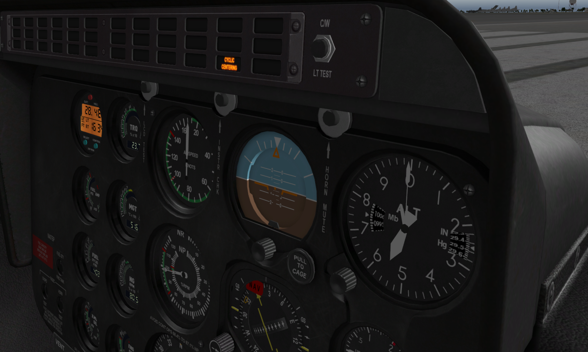
I decided that maybe it’s a good time to update my lever, which was an early version of the MKIII base with a rubber bands mount, to the most recent MKIV EVO version of the lever, partly because I finally found a fair VR configuration for XPlane and thought having a pedestal would be nice, and partly – because the new base has 2 mode switches, and I wanted to test the 2nd one in everyday use and maybe find and fix some related issues. When I finished the build and started looking for the peripheral firmware to flash it, I suddenly understood that there isn’t one.
So, I was quite happy to fix that problem and added some code to support the I2C version of the Simple Collective SE lever (which is actually one of my favorites because of its compact size and rich functionality).
Also, I noticed that the wiring is slightly different from the USB version due to some minor differences in Pro Mini and Pro Micro pinouts, so the manual will follow shortly!
As always, you can find updated files in the simchair4_software repo on GitHub.
Cheers!

Hi.
I would love to build these modules but cannot find on the site all of the .stl files for printing all the parts for a 207 set up..
If you could point me in the right direction, I would appreciate it so much.
Thannks
Hi! All of the STLs for modules are available on GitHub, here: https://github.com/hc625ma/simchair4_models, and the manuals are on the wiki =)
Thank you for the quick response. I think I found everything I need!
All the best.
Will send a few bucks your way tonight
Thanks mate, appreciate it. Please let me know if you have questions =) Please join the Simchair DIY discord channel.
Cheers!
Hi! Quick question. I have a Leo Bodnar 12 bit joystick controller here on the bench. With all of it’s input (analog and digital) and me understanding those boards a bit better than flashing Arduino boards and coding, can’t I simply use the physical parts and build of the collective and throttle you have shared here but base the hall effect sensors and the pots, buttons etc around the Leo Bodnar?
Hi! Yup, you should be able to, however, you may need to use some other means for calibration (I use some functions to map real physical range of sensors to some standard ranges in the firmware). You might also want to route your cables externally (there should be a lot of cables when using analog approach!). You will also loose some special functionality like mode switches, multiple throttle axes support for one physical axis, etc.
I’d say, its actually easier to make it the Arduino way, the code is written already, you just need to select your hardware from the list, adjust the sensor position and enter endpoints, basically, that’s it =)
Thanks for the quick reply. Understood and all good. I will us this as an opportunity to better understand the arduino process and functionality..
Good idea, among everything else the code is something like a universal library/ a collection of examples you can use to create your own joysticks. It covers pretty much anything you can wish for, axes, hat switches, encoders, buttons, switches of several types, interaction between devices, filters, a way of organizing of a lot of code for a lot of optional plugins, etc, its also extendable – you can add your own stuff fairly easily!
Hi Again.
Assuming I need the 5v Mini Pro and not the 3.3v version?
Thanks as always
Yup, the 5v part is important. You will also need the Leonardo compatible board for the master controller, and its better to have an FTDI232 board around just in case you need it.
Cheers!
Hi!
Quick question about uploading firmware to the master controller.
Is the file that needs to be uploaded. a_master.ino? It looks like its only 9 lines of code. Each one starting with #include.. When I verify it, I get an error; Joystick h. No such file directory Thanks for any guidance. If I can get this one right, I think I can sort out the rest.
Found the You tube video and got it all sorted.
All set with firmware.
Cheers
Evening! Quick question about wiring the board into the case of the cyclic. I confused about which pins from the IC2 sockets are the VCC and the GND, I see that pins 3 and 4 are assigned in the wiki page but which pin of 1 and 2 is the VCC? Also same question on the hall effect sensors. I dont want to send VCC down the ground..
Pins all figured out. But… for some reason when trying to flash firmware. joystick.h file not found in Arduino IDE.
Also says cyclic firmware is for USB device. Any help would be appreciated
Hello anyone still on this site. Need some help. I have the master controller all built and flashed OK. I followed the build of the cyclic to the very last detail and have checked all wiring many times over with a multi meter. The Master Controller shows up fine in Joy.cpl but when I attach the cyclic base via the I2C cable I get no response in joystick calibration within Joy.cpl window. I made sure that #define CYCLIC_BASE is uncommented in b_device_definitions. Any help from anyone who has gotten this cyclic base to communicate would be very much appreciated.