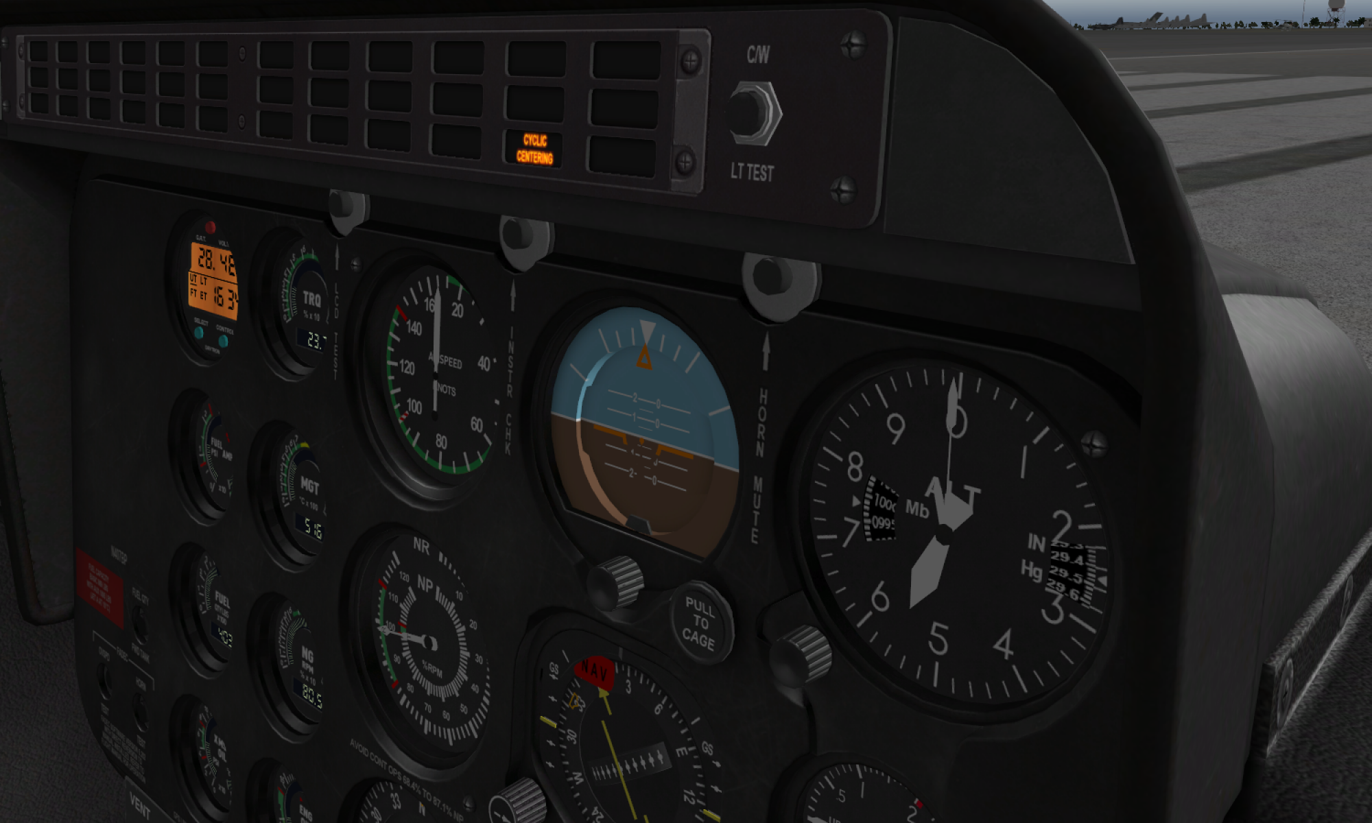
I continued experimenting with white paint marker and acetone and made a “scale” version of a top panel for a 412-style head requested by a friend. In my humble opinion, it looks great, white paint adds some “aging”, and it looks more like it was taken off from a real helicopter. It differs from the original slightly, but has a disctinctly recognizable look overall!
that s looking great!!
Thanks mate! =)
I made such thing for the Huey head. How can I sent it to you so that you can share it.
That’s great! Please upload it here, I will add it to the repo =)
http://hc625ma.org/upload-a-file/
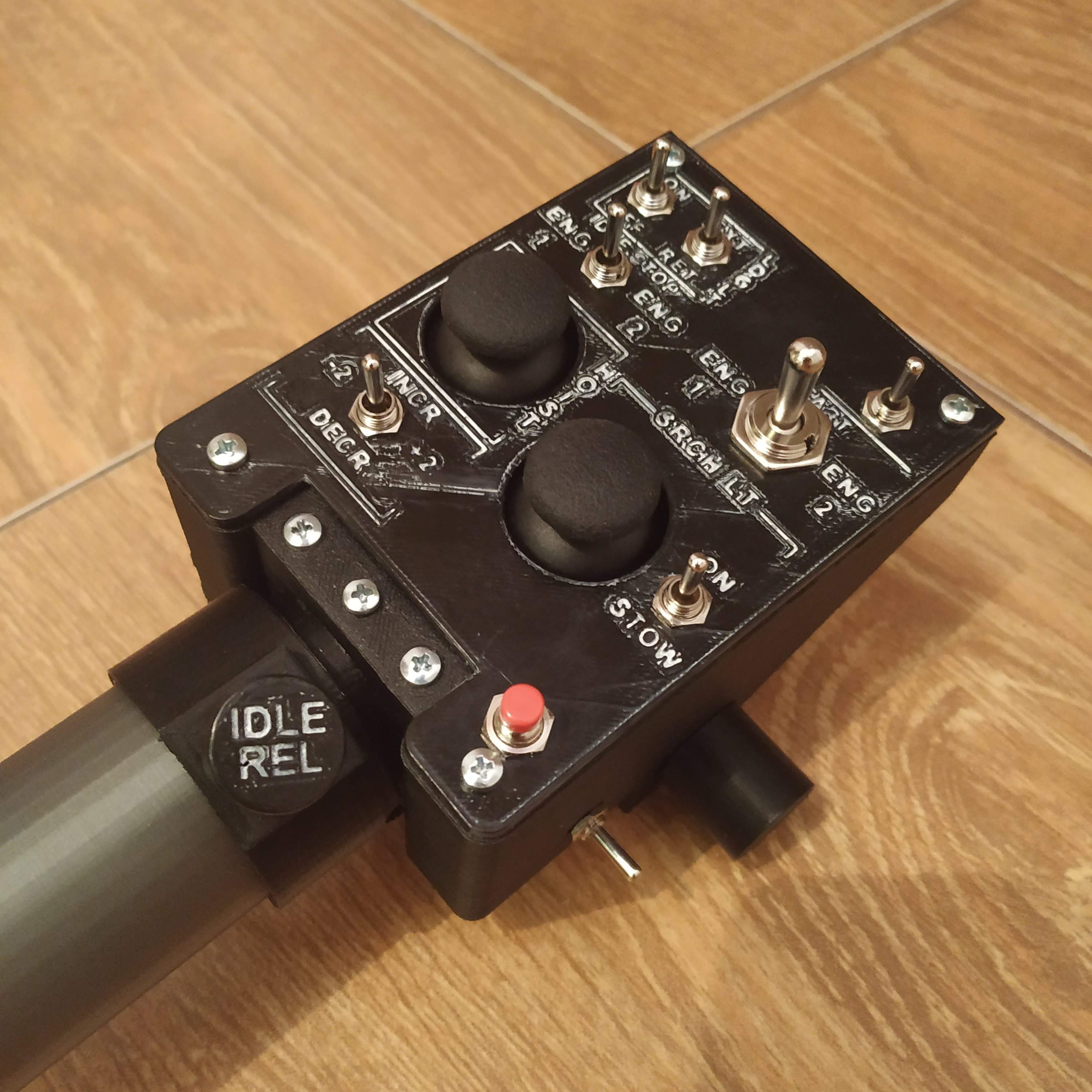
Hello I also made a friction lock a like part for the Huey collective which is suited to fit for the mechanical idle stop switch.
I like to share it.
Thanks
Hello I loaded it up with two pictures.
I added the wihte paint with an 0.8 eding.
regards Christian
Wow looks great!
Do you have a GitHub account? I will gladly grant you write access to the repo! Will add these files to the repo meanwhile. Can you upload source files as well?
Thanks, these things really look epic!
No I haven’t a GitHub account but I can upload the 3dfiles as well. Maybe it takes till weekend. I like to support when ever I made something for your stuff. But now I tried to get the electronic functionality in the collective. Thanks for the feed back and you can do what you want with the files.
Thanks again mate!
Please upload sources as well (someone may want to modify it to suit his needs!)
What do you mean by electronic functionality? How did it go?
I mean the whole welding stuff and cable Salat but I wait for aliexpress delivery.
Ah, I see! Let me know if you need any help =)
I loaded my autodesk 123D file up. So you can use it. Thanks again and what for a big progress in the sofware development by you. Keep up the good work.
by the way my pin of the mechanical idle stop broke after using it 20 times. I printed it with 10% infill. I will print him again with 100%.
kind regrads
Thanks, Christian!
10% is really not enough, I use 40%, 3 perimeters on sides, top and bottom, and slightly increased temperature. But the part may be a bit “delicate” indeed =)
Hello, I have a question regarding the throttle Poti. Yesterday I got my 10k Ohm Potientiometers from Ali. They are too small for to fit in the respective hole. Can I use also 50k Potentiometer?
Thanks
What do you mean they are too small? Are they 16K1 type? I think you can use 50k pots without any issues, as they work as a voltage divider here anyway.
If they just fit too tightly to the hole, you can carefully widen it, I do it every time =)
Thanks for your answer. The thread of the pots are to small. I thought they were 16k1 types but I they aren’t . I have 50k laying around And I try to use them. May project didnt move along as I wish too. I hope in the next weeks I can start for the electronics.
The only thing, make sure they are of “B” (linear) type. Somewhere on them should be written smth like “B50K”.
Hello, after reading the soldering instruction I was asking myself. Do I have to get rid of the Led s on the pro micro. I read this somewhere but couldn’t find it yesterday. Do you changed this?
Yes, you have to remove the led, connected to pin13, every time you use it to connect a switch. Otherwise, the button will always be pressed as the pin is set to “HIGH” (INPUT_PULLUP) and gets grounded on button press! INPUT_PULLUP mode turns on internal resistors of ATMEGA, that are connected between the pin to 5v rail.
Thanks, only to make it clear for me if I don’t use the Pin 13 it is not necessary to get rid of the led? In case of the huey Head it is not necessary?
Yup, if you don’t use the pin, you can leave it there =)
Hello Iam near to give up on the collective:(
I don’t know how to wire. I went to a drawing and read somewhere that is the wrong wiring can you please confirm:
Vcc for pot and hall sensor is pin 10
Sig for the hall is A0
Sig for the pot is A1
Saa A4
scl A5
And can I load the software on the pro mini after wiring.
Tx very much
Hi! No worries, the manual is tested, I actually made quite a few of these. You can simply tie all 5v wires together and solder a wire from that tie to the VCC pin of the Pro Mini. Alternatively, you can use pin 10, it’s set to 5v as well, but simply using VCC seems more straightforward to me. Other pins are correct.
Sure, you can load the firmware after wiring, don’t forget to calibrate the lever. To do it:
1) uncomment “Serial.print” and “Serial.begin” lines
2) comment out these lines:
z = map(z,0,1002,1023,0);
rz = map(rz,83,1023,1023,0);
look for raw z and rz values at endpoints of both axes. Adjust the magnet holder so the values will be close to 0-1023 range. Substitute the values in lines above with the values you see in serial console output, e.g.
rz = map(rz,new_min,new_max,1023,0);
If you need to invert an axis, simply swap two last numbers in a line.
3)Uncomment “map” lines and look at the parsed values, they should be within a range from 0 to 1023. They can be slightly smaller, it’s not a problem.
4)If everything’s fine, comment out “Serial.begin” and “Serial.print” calls.
That’s it! Now, you can do some fine tuning:
5) In master controller firmware, uncomment
// uncomment the next line and turn your throttle to idle stop position to see SINGLE_ENGINE_COLLECTIVE_IDLE_STOP_AXIS_VAL value
//Serial.println(throttle);
//Serial.println(z);
lines under e_single_collective tab, then look at the serial console output and adjust the following values in a_configuration tab:
#define SINGLE_COLLECTIVE_MIN 63
#define SINGLE_COLLECTIVE_MAX 1023
#define SINGLE_COLLECTIVE_THR_MIN 0
#define SINGLE_COLLECTIVE_THR_MAX 1023
and
#define SINGLE_ENGINE_COLLECTIVE_IDLE_STOP_AXIS_VAL 137 (find it out by putting your throttle to the idle stop detent)
#define THROTTLE_LATCH_MODE “PHYSICAL” // PHYSICAL for physical latch mod or TACTILE for levers with tactile marks
6) Comment out Serial.print calls and enjoy flying with perfectly tuned lever! =)
P.S. it may seem a bit scary if you never tried it, but don’t worry, it’s actually very simple. If you will run into problems, I can help you through Anydesk session.
Cheers!
Thanks for the detailed answer!
Regards
You’re welcome! I forgot to mention, that when making changes to the firmware, you should reflash the board =) Also, Pro Mini needs to be reset manually in the process of flashing, just press reset button when the orange lines at the bottom of the screen in Arduino IDE stop running.