Strengthened gimbal first flight impressions

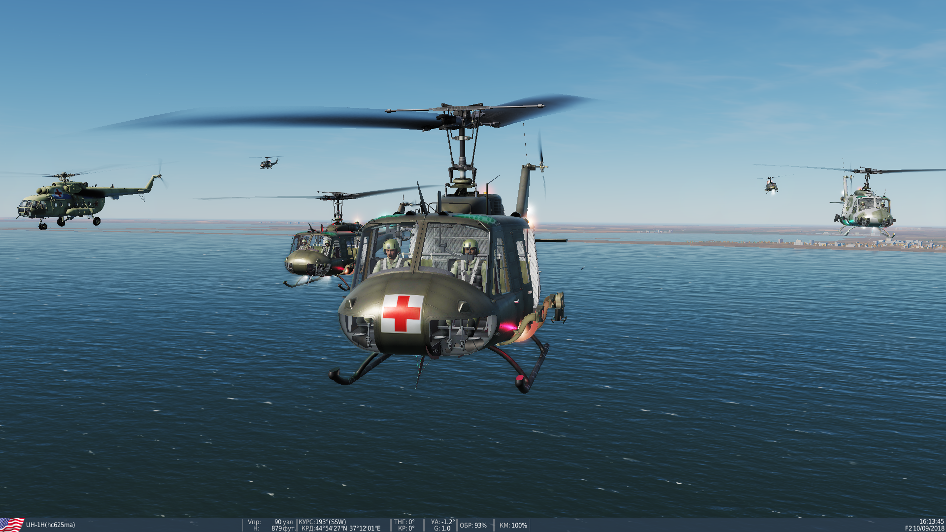
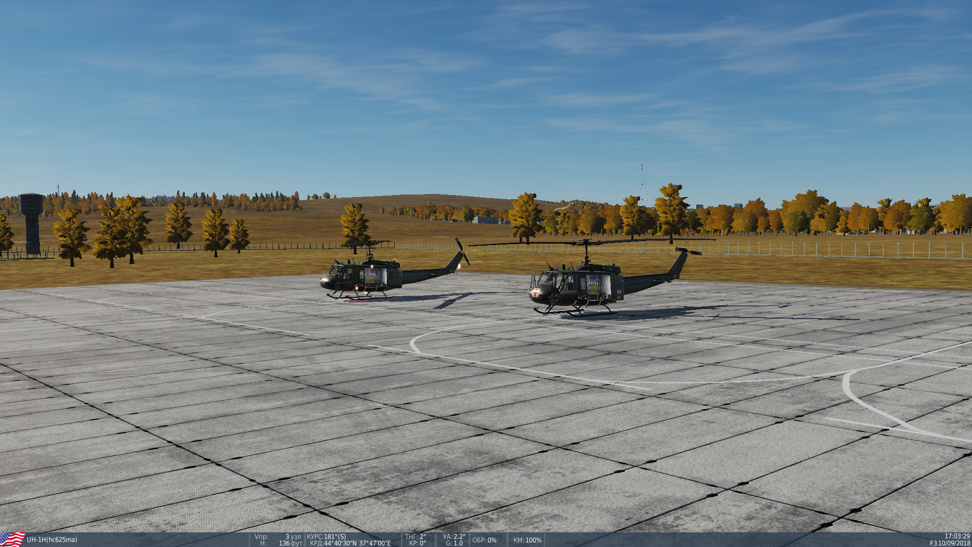
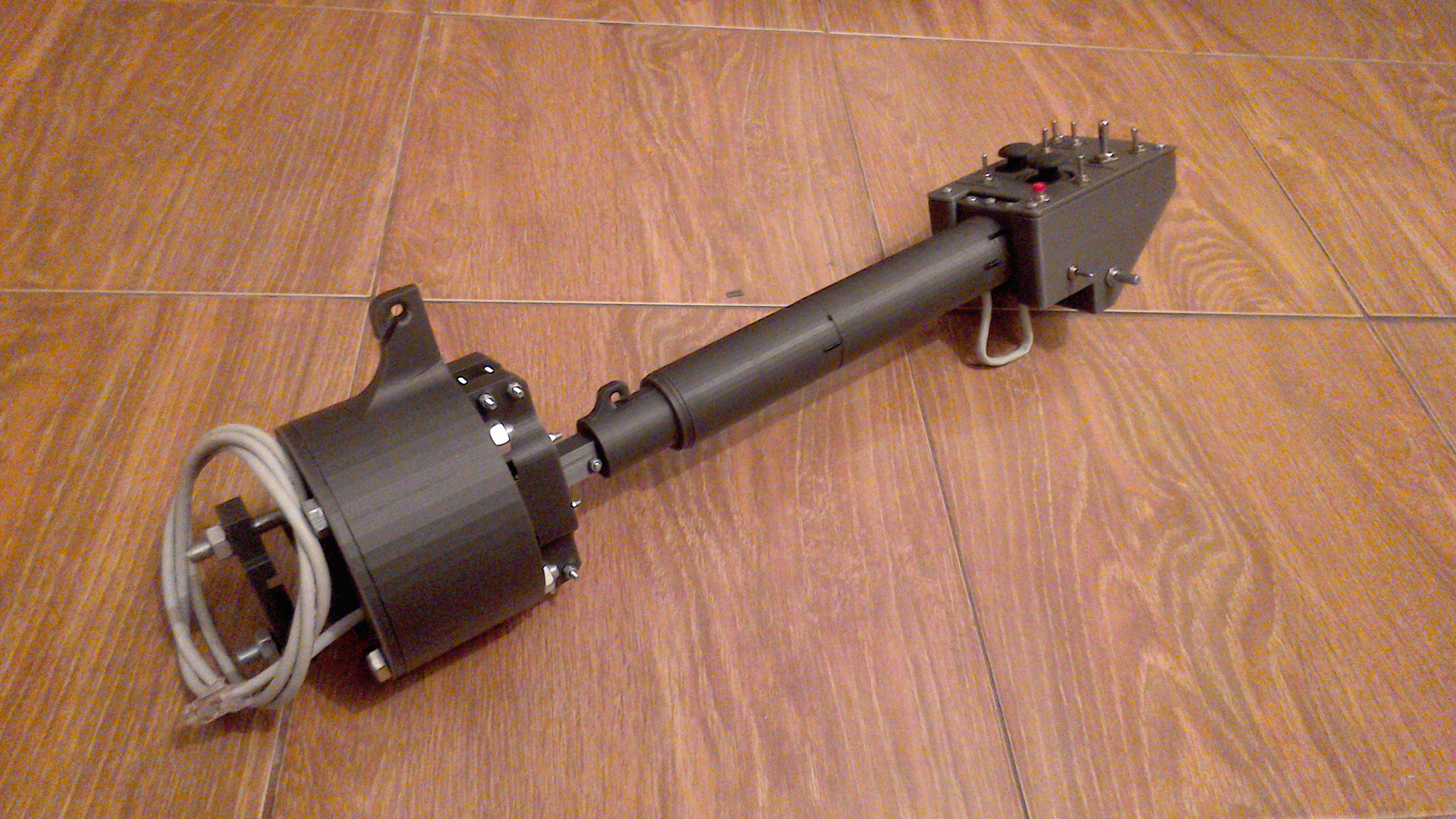
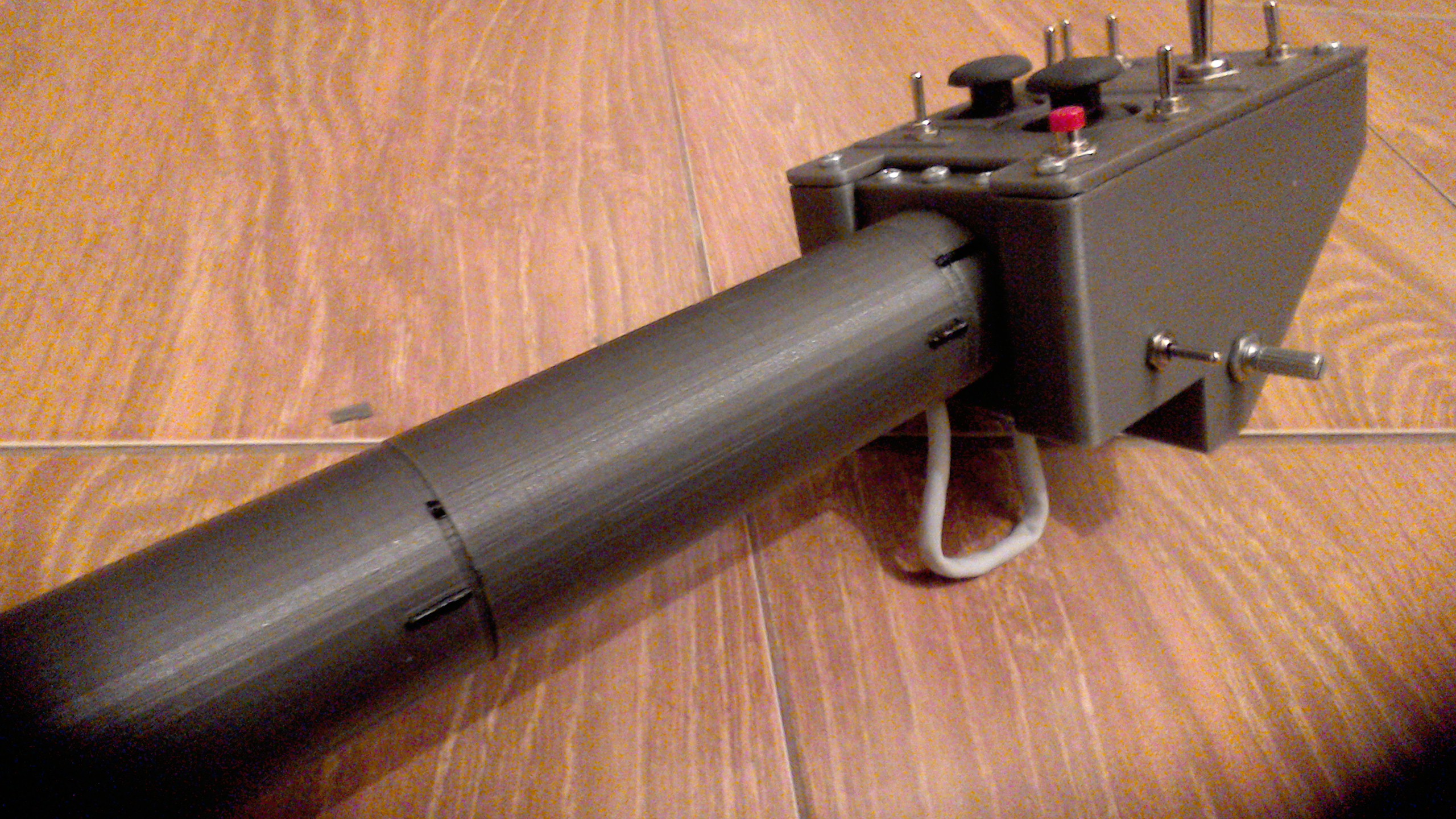
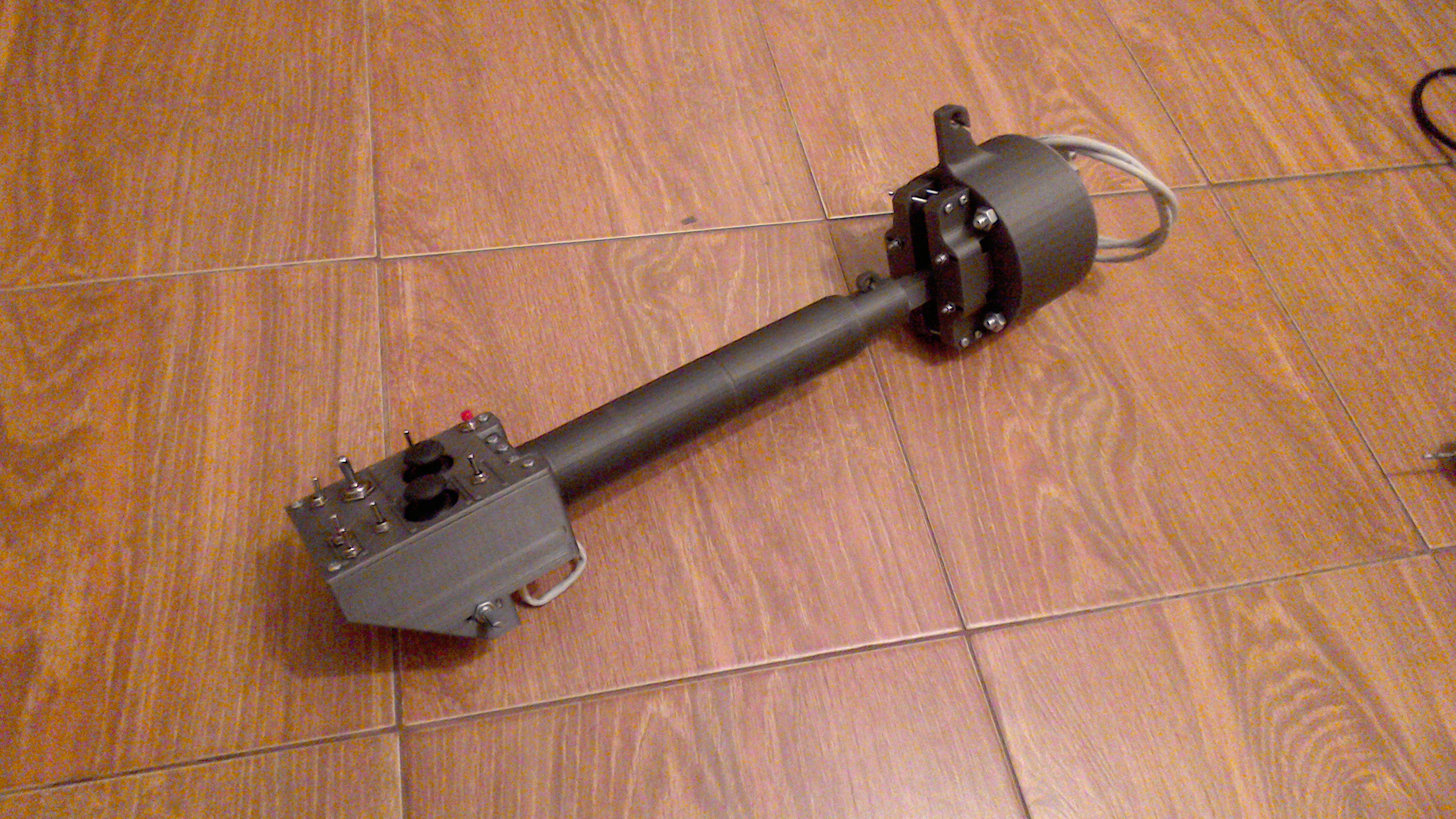
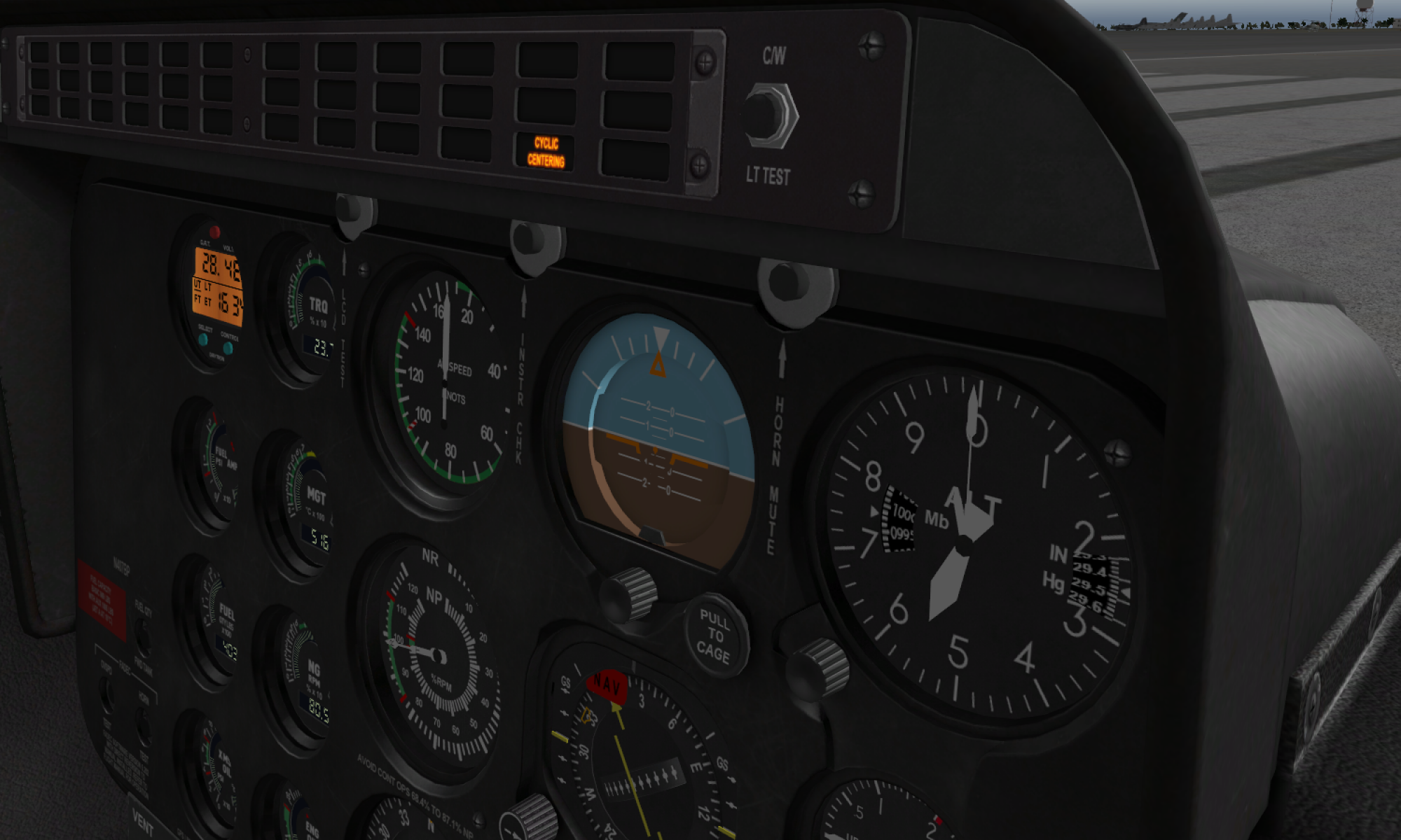
I have finally managed to build the gimbal, and even tried flying with it on Aerobatics Online Caucasus sever in DCS =)

I can say it’s great! For now, I’ve used rubber bands for stick centering, and they work pretty well. I noticed that I haven’t been using the software force trim function much during this flight. A lot of heli pilots were online, so I’ve had a great opportunity to put both the gimbal and pneumatic mod for the collective to a good test 😀

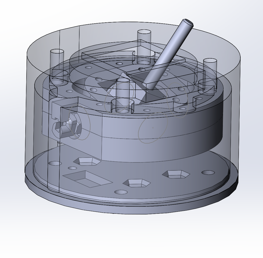
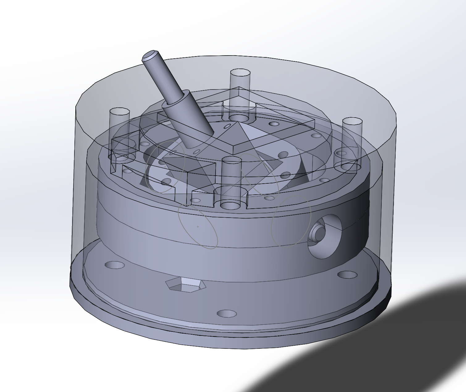
I am waiting for 50mm MAL16-50 pneumatic cylinders to arrive, hopefully with them installed the stick will feel perfect.  The collective pneumatic mod still holds together, I am beginning to think it’s really safe to use. A couple more weeks will show if I am wrong =) The new gimbal will be released tomorrow, if time permits, I will also be making a couple of videos about the new stuff soon.

Stay tuned!

Me leading a humble formation 😀
And following another ship, the gimbal has been performing great!
Feels fine when maneuvering in ground effect as well =)

Thoughts on MLX90333

After finally getting some long enough sleep I thought again on my failed attempts with a Melexis sensor. The sensor itself is quite precise and has some DSP onboard, so I tried it again with a spherical gimbal and noticed that depending on how close a magnet is to the sensor, it outputs not a circle, but a square, inclined to 45 degrees. I thought, “- what if I simply cut excess values and make it a square?”, and did just that. The idea behind it was that jitter of the point in a joystick tester sketch seemed minimal,  so the physical precision of the sensor looked like being enough to work well. As long as we have a 15 bit external ADC that powers our gimbal, we should still have something like 4096 points per axis even with this reduced range, which is plenty.

Now, if we use a disk magnet instead of a square one, unarrested twist axis is not an issue anymore, it doesn’t affect X and Y positions in a big way. So this design seems to be perfectly fine for vertical sticks, or sidesticks, and I think with a pneumatic mod it can be as good for everything else. Its beauty lies in its mechanical simplicity, only a few parts are needed, it can be quite small in size.

I think I will make, test and publish both versions so everyone will be able to choose something for himself =) There’s also a third version, the 608 and MLX based one, its fate will depend on a degree of success of the spherical bearing based one =)


Meanwhile, some progress on the 608 and SS495A based version:

Reinforced 608 and SS495A based gimbal
The gimbal itself is quite strong, it should be able to handle the load!)

News on a strengthened gimbal

I’ve printed and assembled both versions I was talking about in the previous post, and sadly, I had to revert to using SS495A sensors. That’s because the MLX sensor is not so good at displaying values at the angles of the square, like x:1000,y:1000 or x:10,y:10. It also has quite a high jitter near edges of axes. If someone has some experience with these MLX sensors (I am probably doing smth wrong) plz share it with me =)

Meanwhile, I’ve redesigned the new gimbal for use with trusty old SS495A sensors. I am pretty sure it still needs some adjustments, but it uses the same distance from sensor to the magnet, and same 6x6x4 magnets (5x5x5 mod will be available as usual) as well, so I think we will see it in action soon enough.

Here’s how it looks:

Thoughts on strenthened flight stick gimbals

I am now working on two reinforced gimbal variants. One of them is based on an ordinary 608 skateboard bearings, another one – GE25 ES-2RS spherical bearing. Both of them will be able to handle springs, rubber bands, pneumatic cylinders, etc. A CJMCU-93 module (MLX90333) is used as a magnetic field sensor.

The fate of GE25 ES-2RS one depends on whether I will be able to prevent it from twisting or not (i have an idea involving _| shaped bracket, 2 pneumatic cylinders, and 2 spherical heads now). If you have some ideas about how to lock “twist axis” of a spherical bearing, please share them in comments =) Here are some pictures of the GE25 testbed and 608-based design.

608-based strengthened gimbal
GE25 spherical bearing based gimbal, it’s cute, but the “twist” axis kills all the fun!

AB412 collective head switch configuration tutorial

I have fixed some switch operation related bugs today and decided to make a video to show how to configure a collective head to suit your needs. Different sims can require different switch setups, for example, DCS Huey uses 3 of 4 modes for its collective head.

There are 4 switch modes, to assign a switch or a button to one of them look its joystick button number in joy.cpl and add it to one of the following  arrays:

    • ab412_sw_mode_button_switches – push button mode – joystick button is pressed when you hold the switch, supports mode switch
    • ab412_sw_mode_toggle_switches – toggle switch mode – when the switch goes up, joystick button is pressed and released, when it goes back to the middle position – the button is pressed and released again (example : gear lever), ignores mode switch setting
    • ab412_sw_mode_selector_button_switches – maps a 3-way switch to 3 joystick buttons, one for “up” position, one for “down”, one for “middle”. Buttons are pressed when the switch is being held pressed. Example: landing light switch – up-hold-down.
    • ab412_sw_mode_selector_switches – same as the previous one, but joystick buttons are pressed and released. This is there in case someone needs it for something.

For first two types, you put buttons one by one to the array (one switch is 2 joystick buttons, so if the switch shows as buttons 3 and 4 in joy.cpl, you write both 3 and 4 to the corresponding array), for last two types you only write the lesser of two switch buttons (lets say a switch shows as buttons 14 and 15 in joy.cpl, then you only have to write 14). Do not forget to remove switch and button numbers from their previous mode array when you assign them to another mode.

If something needs more detailed explanation, or if you want some other interesting switch mode, please ask in comments!

Twin trottle collective improvements

While building the twin lever, I’ve decided to change the design of the throttle 1 frame p2 part to make throttle grips tension equal. The part now has a detent in it, that can also add some rigidness to the lever. If you’re building the twin lever, definitely use the new part! All updates are already on GitHub! I will be adding a similar part for the single throttle collective shortly.

Also made some fixes to AB412 head mods and software (added support for an extra mode switch)

Here’s how the latest version of the lever looks:

The new frame connector allows for backlash-free operation and easy mounting
This AB412 head version features two rotary side pots and a mode switch
Software idle stop positions are colored in black
The lever feels quite rigid, I like it!

B8 stick build impressions

Have just finished assembling the B8 stick grip. I can say that the manual here is perfectly correct, have soldered everything as it says and it worked immediately after flashing. No setup required, just flash it. The only thing that needs tweaking is the size of nut sockets – they are too tight, will make them a bit bigger.  Quite perfect otherwise!

A major cleanup

Hi guys, very good news here. All the stuff is finally on GitHub! Everything is updated to the very latest version, STLs are oriented correctly, just download, print, and fly.

This repo will be the only supported place to get the stuff from now on. I will add “Downloads” section with a current snapshot of the repo to this site. All the stuff on thingiverse was reorganized and files were replaced with the corresponding links to GitHub (this way you’ll always get the latest stuff without any extra effort from me).

The simple collective was removed, as we don’t really need it anymore because both single throttle and twin throttle levers feel as good, but also support heads. Let me know if you want it back.

Cheers!