
For those of you guys who use IKEA GUNDE chair, fly Hueys, or 412, or whatever else has its collective mounted at an angle, here’s a nice lever mount that should place the Simchair one in a way that’s pretty similar to the real thing:
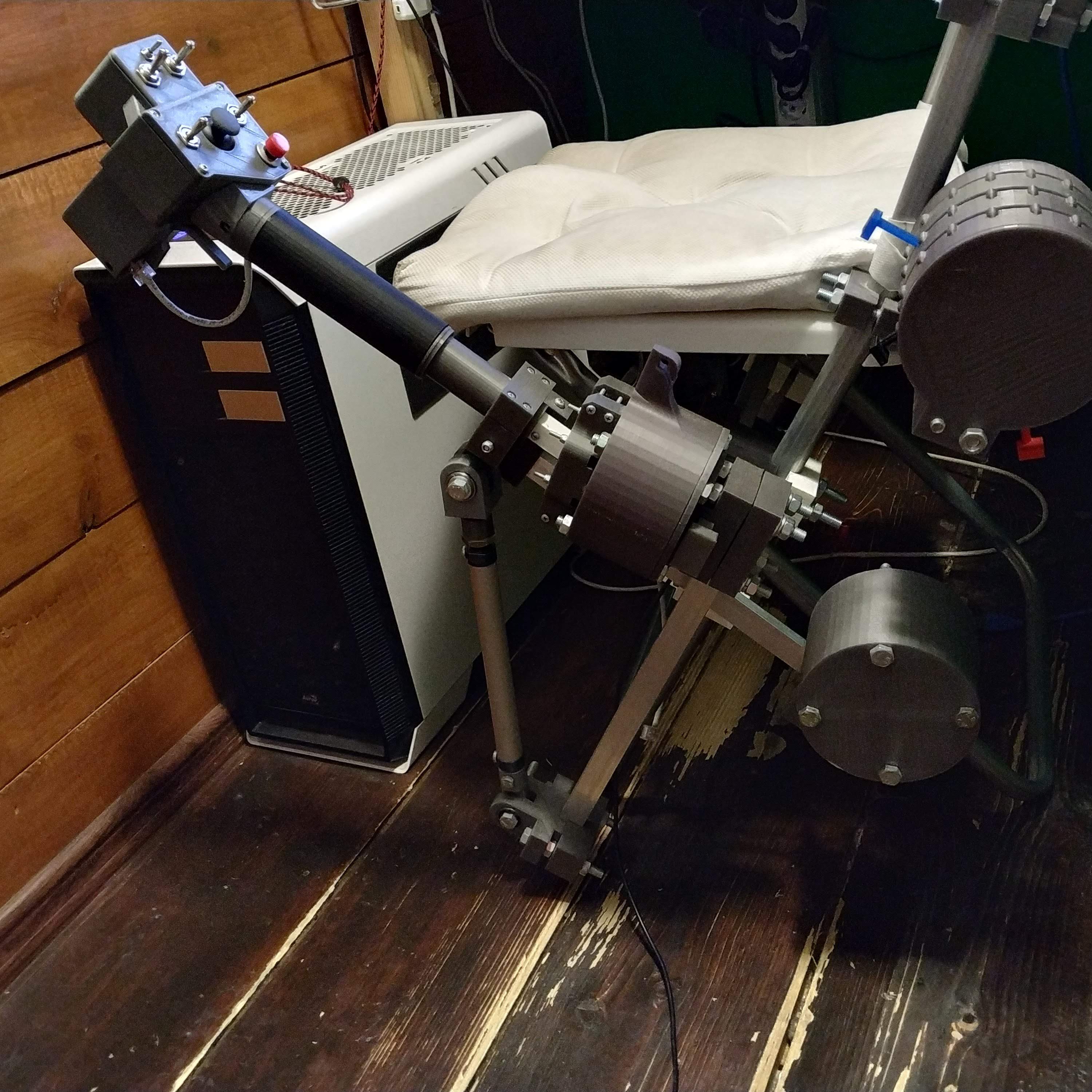
No changes to the lever itself required, just flip the counterweight box to the other side of the lever and move it slightly further down the rail.
As always, you can download files from the repo.
Enjoy!
Hello,
After some time I give the collective a new try still fighting with electronics but it seems to work this time. But I have a question regarding the switches in the Huey head. Why do you use for on off on switches for the SL + Ldg light switches?
Thanks
Hi Christian! Glad it finally worked for you! Just to make it more universal. The Huey head only has so many buttons, so I used any possibility to add more =) You can always make a 2-way switch out of a 3-way, but not another way. You can use on-off ones, will probably have to adjust the configuration matrix a bit.
Is it possible to get an option for an poti for the collective lever arm? The problems with the electric is still there. So I will try next week to get it runing. If it’s not going well I have to change the electric for a bodnar Board. But this time I will try to use a poti instead of the hall sensor. Thank you very much for your great work.
Christian, no need to, let’s do Anydesk session, I will help you =) Fitting potentiometer there is impossible because you will need a gearbox to turn ~300 degrees of pot rotation angle into ~40 degrees of lever travel. Electrically, there’s no difference between the 495A sensor and the potentiometer – just power it with 5v and read signal =)
please join the discord channel: https://discord.gg/3XuZMDY
Okay i got the Head Running. But the following switches are not operating
SL put in a on off on sw on connected to txd / Rx and ground.
The head switch connected to pin 12 and
A additional momentary switch instead of the small toogle sw between SL and Ldg Lt connected to Pin 3
I suspect that the Programm is maybe not made for. I got help from Felix how wrote you and he has the same problems. Unfortunately Iam often in areas with only poor internet so I can’t do any desk
Thanks
hmm at first, try disabling mode switch by setting 0 in
#define HUEY_COLL_HEAD_MODE_SWITCH 0
then, change the switch matrix like that:
const sw_matrix huey_switch_matrix[] PROGMEM =
{
// i t m is i – id, t – type, m – middle button for types 3 and 4
{1, 3, 33},
{2, 5, 33},
{3, 1, 0}, // buttons 3 and 4 are mode switch
{4, 1, 0},
{5, 2, 0},
{6, 2, 0},
{7, 1, 0},
{8, 1, 0},
{9, 3, 34},
{10,5, 34},
{11,1, 0},
{12,1, 0},
{13,1, 0},
{14,0, 0},
{15,0, 0},
{16,0, 0},
{17,0, 0},
{18,0, 0},
{19,0, 0},
{20,0, 0},
{21,0, 0},
{22,0, 0},
{23,0, 0},
{24,0, 0},
{25,0, 0},
{26,0, 0},
{27,0, 0},
{28,0, 0},
{29,0, 0},
{30,0, 0},
{31,0, 0},
{32,0, 0},
};
Can you tell me how exactly things are wired and what is connected to which pin? To speed things up, I would recommend wiring things exactly as described in the manual, as you have to change the switch matrix for different configurations =) It’s not hard to do though.
The switch on pins 2 and 3 is a mode switch – a special switch that selects a set of joystick buttons to which physical buttons are mapped.
I took the picture you provided for the Huey head I took even the same colors
Hmm, so it’s wired exactly like in the manual with no deviations? No 2-way switches instead of 3-way or smth like that? I may have misread your previous comment?
If so, can you tell me which of these switches do not work? Or if you have changed something, can you please mark what is changed and how on the scheme below (o’s are switch positions, the top one is the small switch in the middle, and so on, sorry for formatting, site engine “improves” the post by eating spaces)?
________o

____o________o

________O

__o____________o

_______________o
I put in a 3 way switch because you mentioned it.
It was the left button below the small upper switch. And the switch on the 4 way switch.
Ah, the button on a thumbstick actually works as collective trim! it disables collective input when pressed and when pressed again – unlocks it when the lever is within 5% deviation from its initial trim position.
The button might haven’t been working because in mode switch positions other than 0 it will be pressing buttons with number > 32, and joy.cpl can only show first 32 buttons =)
It was the left button below the small upper switch. And the switch on the 4 way switch.
So after I got the help from Felix and we changed the mode switch to off we got all switches running. After that we went for the collective and got even that running but I need 5o know how to power Pin 10 to get another Vcc because the board had only two to fire both the hall sensor and the poti. The hall sensor is calibrated. The next step is to put all together and cable the thing.
Thank you for your help. Ah we changed the board maybe that did the trick.
Thanks
I am glad you’ve sorted it out =) Please join the discord channel (https://discord.gg/3XuZMDY) – I’ll try to help you in “live” mode.
The thing is, it looks like everything was working as intended- the mode switch actually adds more buttons, e.g. the same idle release button will be pressing 3 different joystick buttons in different mode switch positions! If you need that, you can turn it back on and look at how it works in online html5 gamepad tester:
https://html5gamepad.com/
The mode switch itself does not send joystick button presses when acting as a mode switch.
you can power pin 10(or any other) with the following lines:
under setup subroutine, add 2 lines:
void setup()
{
pinMode(10, OUTPUT); // turn 5v on pin 10
digitalWrite(10, HIGH);
Alternatively, just tie +5v wires together, and solder one wire to VCC pin of the Arduino board.
Cheers!
Hello,
a question regarding the pro mini´s. Can I connect the sda, scl GND, Vcc from the two Pro minis of the collective and connect them to one Ethernet cable for the master?
Yes, absolutely! =) This is the right way to do it.